Page 1280 of 2643
5–120WELECTRICAL WIRING DIAGRAMS
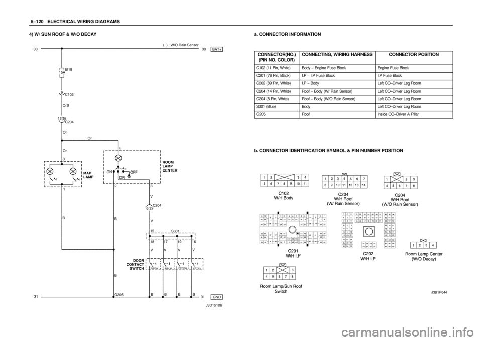
4) W/ SUN ROOF & W/O DECAYa. CONNECTOR INFORMATION
CONNECTOR(NO.)
(PIN NO. COLOR)
CONNECTING, WIRING HARNESSCONNECTOR POSITION
C102 (11 Pin, White)Body � Engine Fuse BlockEngine Fuse Block
C201 (76 Pin, Black)I.P � I.P Fuse BlockI.P Fuse Block
C202 (89 Pin, White)I.P � BodyLeft CO–Driver Leg Room
C204 (14 Pin, White)Roof � Body (W/ Rain Sensor)Left CO–Driver Leg Room
C204 (8 Pin, White)Roof � Body (W/O Rain Sensor)Left CO–Driver Leg Room
S301 (Blue)BodyLeft CO–Driver Leg Room
G205RoofInside CO–Driver A Pillar
b. CONNECTOR IDENTIFICATION SYMBOL & PIN NUMBER POSITION
J3B1P044
Page 1340 of 2643
5–180WELECTRICAL WIRING DIAGRAMS
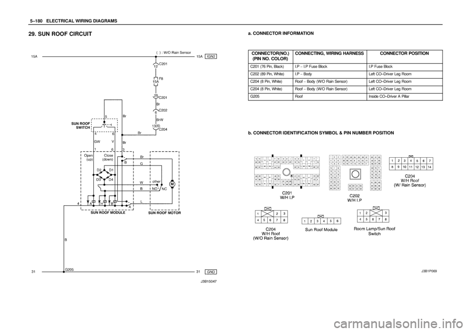
29. SUN ROOF CIRCUITa. CONNECTOR INFORMATION
CONNECTOR(NO.)
(PIN NO. COLOR)
CONNECTING, WIRING HARNESSCONNECTOR POSITION
C201 (76 Pin, Black)I.P � I.P Fuse BlockI.P Fuse Block
C202 (89 Pin, White)I.P � BodyLeft CO–Driver Leg Room
C204 (8 Pin, White)Roof � Body (W/O Rain Sensor)Left CO–Driver Leg Room
C204 (8 Pin, White)Roof � Body (W/O Rain Sensor)Left CO–Driver Leg Room
G205RoofInside CO–Driver A Pillar
b. CONNECTOR IDENTIFICATION SYMBOL & PIN NUMBER POSITION
J3B1P069
Page 2220 of 2643
9A – 14IBODY WIRING SYSTEM
DAEWOO V–121 BL4
I/P Fuse Block
FuseRating/SourceCircuit
F110AIGN 1SDM
F210AIGN 1TCM, ECM, Generator, VGIS, VSS
F315AIGN 1Hazard Switch
F410AIGN 1Cluster, DRL Module, Chime Bell, Brake Switch,
SSPS Module, A/C Control Switch
F5–Spare–
F610AIGN 2A/C Comp. Relay, Defog Relay, Power Window
Relay, Head Lamp Relay
F720AIGN 2Blower Relay, A/C Control Switch, FATC
F815AIGN 2Electric Mirror Switch, Folding Mirror, Sun Roof
Module
F925AIGN 1Wiper Motor, Wiper Switch
F10–Spare–
F1110AIGN 1EBCM, Oil Feeding Connector
F1210AIGN 1Immobilizer, Anti Theft Control Unit, Rain Sensor
Unit
F1310AB+TCM
F1415AB+Hazard Switch
F1515AB+Anti Theft Control Unit
F1610AB+DLC
F1710AACCAudio, Clock
F1815AACCExtra Power Jack
F1915AACCCigar Lighter
F2010AIGN 1Reverse Lamp Switch, PNP Switch
F2115AB+Rear Fog Relay
F2215AB+Clock, FATC, A/C Control Switch
F2315AB+Audio
F2410AB+Immobilizer
Page 2339 of 2643
9F – 10IAUDIO SYSTEMS
DAEWOO V–121 BL4
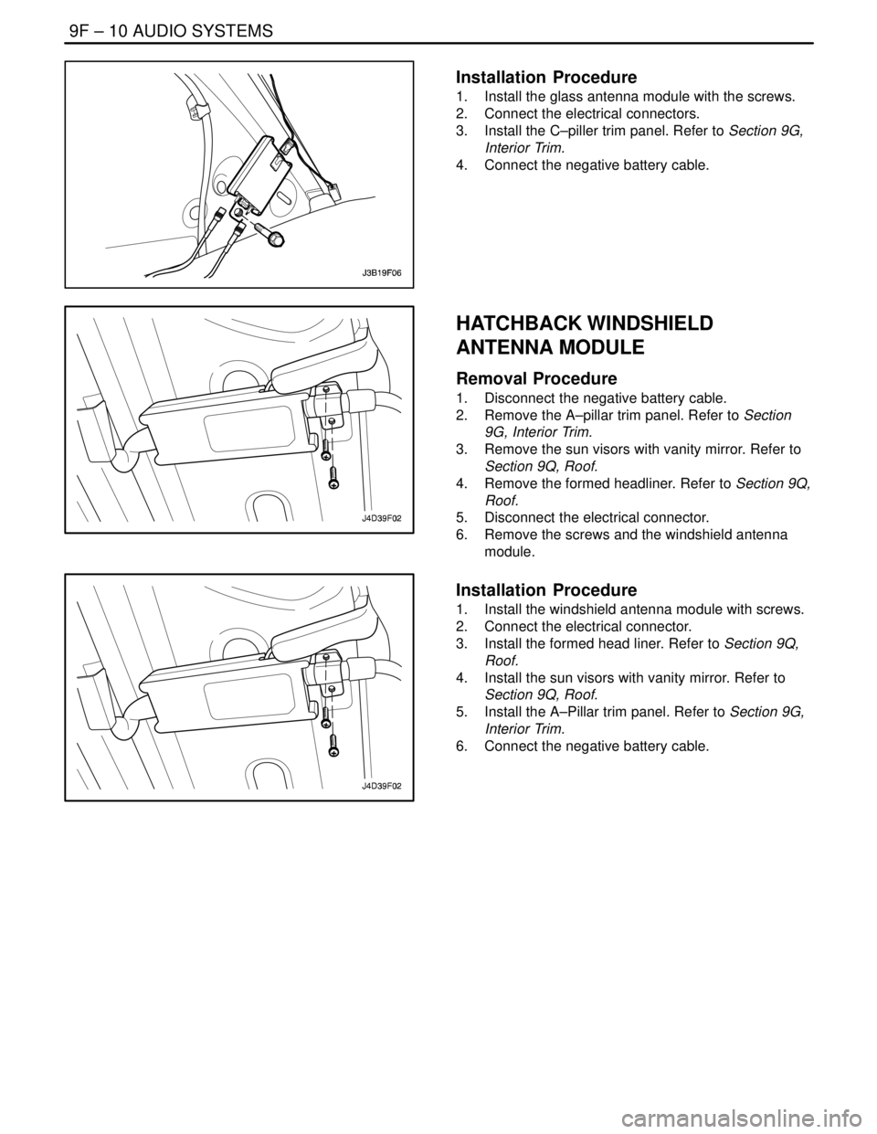
Installation Procedure
1. Install the glass antenna module with the screws.
2. Connect the electrical connectors.
3. Install the C–piller trim panel. Refer to Section 9G,
Interior Trim.
4. Connect the negative battery cable.
HATCHBACK WINDSHIELD
ANTENNA MODULE
Removal Procedure
1. Disconnect the negative battery cable.
2. Remove the A–pillar trim panel. Refer to Section
9G, Interior Trim.
3. Remove the sun visors with vanity mirror. Refer to
Section 9Q, Roof.
4. Remove the formed headliner. Refer to Section 9Q,
Roof.
5. Disconnect the electrical connector.
6. Remove the screws and the windshield antenna
module.
Installation Procedure
1. Install the windshield antenna module with screws.
2. Connect the electrical connector.
3. Install the formed head liner. Refer to Section 9Q,
Roof.
4. Install the sun visors with vanity mirror. Refer to
Section 9Q, Roof.
5. Install the A–Pillar trim panel. Refer to Section 9G,
Interior Trim.
6. Connect the negative battery cable.
Page 2450 of 2643

SECTION : 9Q
ROOF
CAUTION : Disconnect the negative battery cable before removing or installing any electrical unit or when a tool
or equipment could easily come in contact with exposed electrical terminals. Disconnecting this cable will help
prevent personal injury and damage to the vehicle. The ignition must also be in LOCK unless otherwise noted.
TABLE OF CONTENTS
SPECIFICATIONS9Q–2 . . . . . . . . . . . . . . . . . . . . . . . . . .
Fastener Tightening Specifications 9Q–2. . . . . . . . . . .
SPECIAL TOOLS9Q–2 . . . . . . . . . . . . . . . . . . . . . . . . . . .
Special Tools Table 9Q–2. . . . . . . . . . . . . . . . . . . . . . . .
SCHEMATIC AND ROUTING DIAGRAMS9Q–3 . . . . .
Power Sunroof System 9Q–3. . . . . . . . . . . . . . . . . . . . .
DIAGNOSIS9Q–4 . . . . . . . . . . . . . . . . . . . . . . . . . . . . . . . .
Power Sunroof 9Q–4. . . . . . . . . . . . . . . . . . . . . . . . . . . .
MAINTENANCE AND REPAIR9Q–6 . . . . . . . . . . . . . . .
ON–VEHICLE SERVICE 9Q–6. . . . . . . . . . . . . . . . . . . . .
Power Sunroof 9Q–6. . . . . . . . . . . . . . . . . . . . . . . . . . . .
Sun Shade 9Q–7. . . . . . . . . . . . . . . . . . . . . . . . . . . . . . . . Sunroof Glass 9Q–8. . . . . . . . . . . . . . . . . . . . . . . . . . . . .
Formed Headliner 9Q–8. . . . . . . . . . . . . . . . . . . . . . . . .
Sun Visors with Vanity Mirror 9Q–10. . . . . . . . . . . . . . .
Passenger Assist Handles 9Q–10. . . . . . . . . . . . . . . . .
Power Sunroof Control Switch 9Q–11. . . . . . . . . . . . . .
GENERAL DESCRIPTION AND SYSTEM
OPERATION9Q–12 . . . . . . . . . . . . . . . . . . . . . . . . . . . . .
Roof 9Q–12. . . . . . . . . . . . . . . . . . . . . . . . . . . . . . . . . . . .
Power Sunroof/Sunroof Control Switch 9Q–12. . . . . .
Sun Visors with Vanity Mirror 9Q–12. . . . . . . . . . . . . . .
Passenger Assist Handles 9Q–12. . . . . . . . . . . . . . . . .
Coat Hooks 9Q–12. . . . . . . . . . . . . . . . . . . . . . . . . . . . . .
Page 2451 of 2643
9Q – 2IROOF
DAEWOO V–121 BL4
SPECIFICATIONS
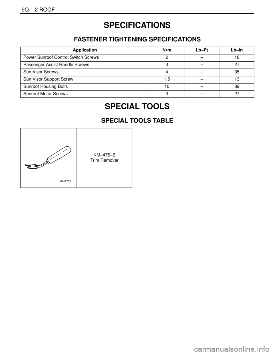
FASTENER TIGHTENING SPECIFICATIONS
ApplicationNSmLb–FtLb–In
Power Sunroof Control Switch Screws2–18
Passenger Assist Handle Screws3–27
Sun Visor Screws4–35
Sun Visor Support Screw1.5–13
Sunroof Housing Bolts10–89
Sunroof Motor Screws3–27
SPECIAL TOOLS
SPECIAL TOOLS TABLE
KM–475–B
Trim Remover
Page 2452 of 2643
ROOF 9Q – 3
DAEWOO V–121 BL4
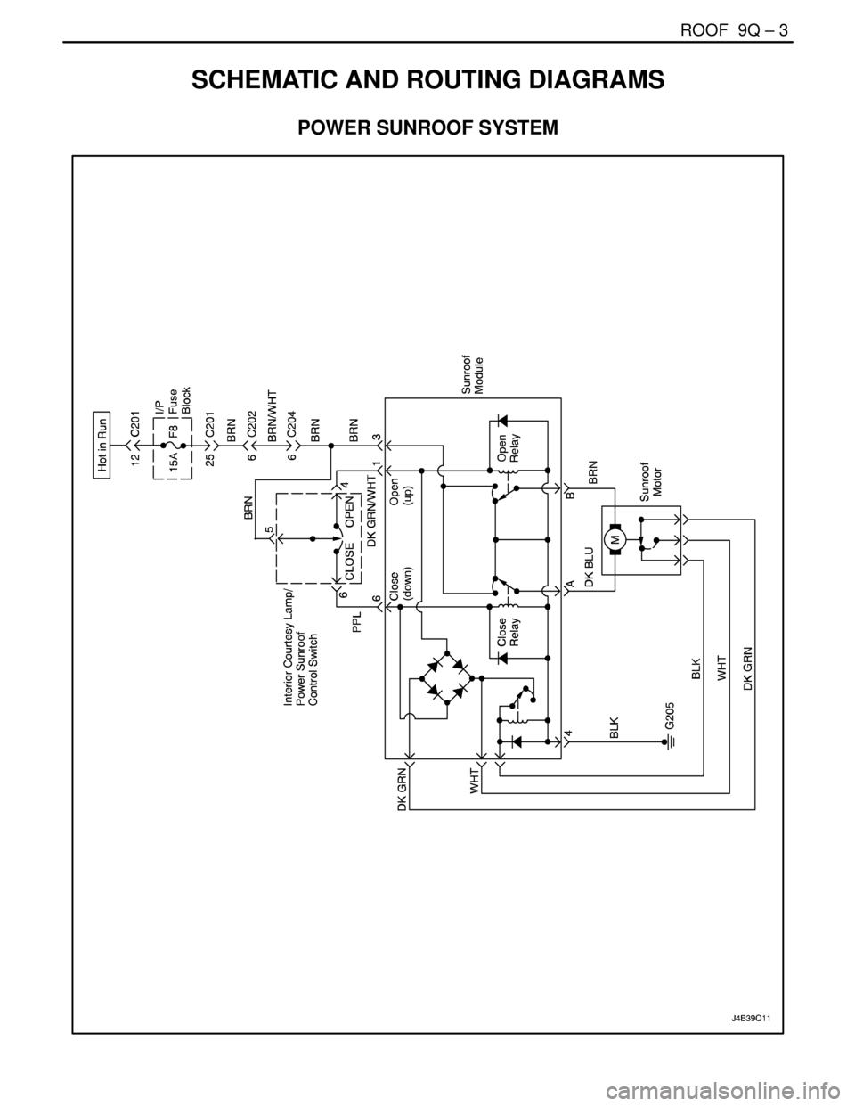
SCHEMATIC AND ROUTING DIAGRAMS
POWER SUNROOF SYSTEM
Page 2453 of 2643

9Q – 4IROOF
DAEWOO V–121 BL4
DIAGNOSIS
POWER SUNROOF
Power Sunroof Does Not Work
StepActionValue(s)YesNo
1Check fuse F8.
Is either fuse blown?–Go to Step 2Go to Step 3
21. Check for a short circuit and repair it, if neces-
sary.
2. Replace the blown fuse.
Is the repair complete?–System OK–
31. Turn the ignition on.
2. Check the voltages at fuse F8.
Are both voltages equal to the specified value?11 – 14 vGo to Step 5Go to Step 4
4Repair the power supply to the fuse which did not in-
dicate battery voltage with the ignition on.
Is the repair complete?–System OK–
51. Disconnect the interior courtesy lamp/power
sunroof control switch connector.
2. Turn the ignition on.
3. Check the voltage at terminal 5 of the interior
courtesy lamp/power sunroof control switch
connector.
Is the voltage equal to the specified value?11–14 vGo to Step 7Go to Step 6
6Repair the open circuit between fuse F8 and the inte-
rior courtesy lamp/power sunroof control switch con-
nector.
Is the repair complete?–System OK–
71. Reconnect the interior courtesy lamp/power
sunroof control switch connector.
2. With the sunroof switch in the OPEN position,
check the voltage at terminal 4 of the interior
courtesy lamp/power sunroof control switch
connector.
3. With the sunroof switch in the CLOSE position,
check the voltage at terminal 6 of the interior
courtesy lamp/power sunroof control switch
connector.
Do both voltages equal the specified value?11 – 14 vGo to Step 9Go to Step 8
8Replace the interior courtesy lamp/power sunroof
control switch.
Is the repair complete?–System OK–
91. Disconnect the sunroof module connector.
2. With the sunroof switch in the OPEN position,
check the voltage at terminal 1 of the sunroof
module connector.
3. With the sunroof switch in the CLOSE position,
check the voltage at terminal 6 of the sunroof
module connector.
Are the voltages equal to the specified value?11–14 vGo to Step 11Go to Step 10