2004 DAEWOO LACETTI Rod
[x] Cancel search: RodPage 44 of 2643
SECTION : 1C1
1.4L/1.6L DOHC ENGINE MECHANICAL
CAUTION : Disconnect the negative battery cable before removing or installing any electrical unit or when a tool
or equipment could easily come in contact with exposed electrical terminals. Disconnecting this cable will help
prevent personal injury and damage to the vehicle. The ignition must also be in LOCK unless otherwise noted.
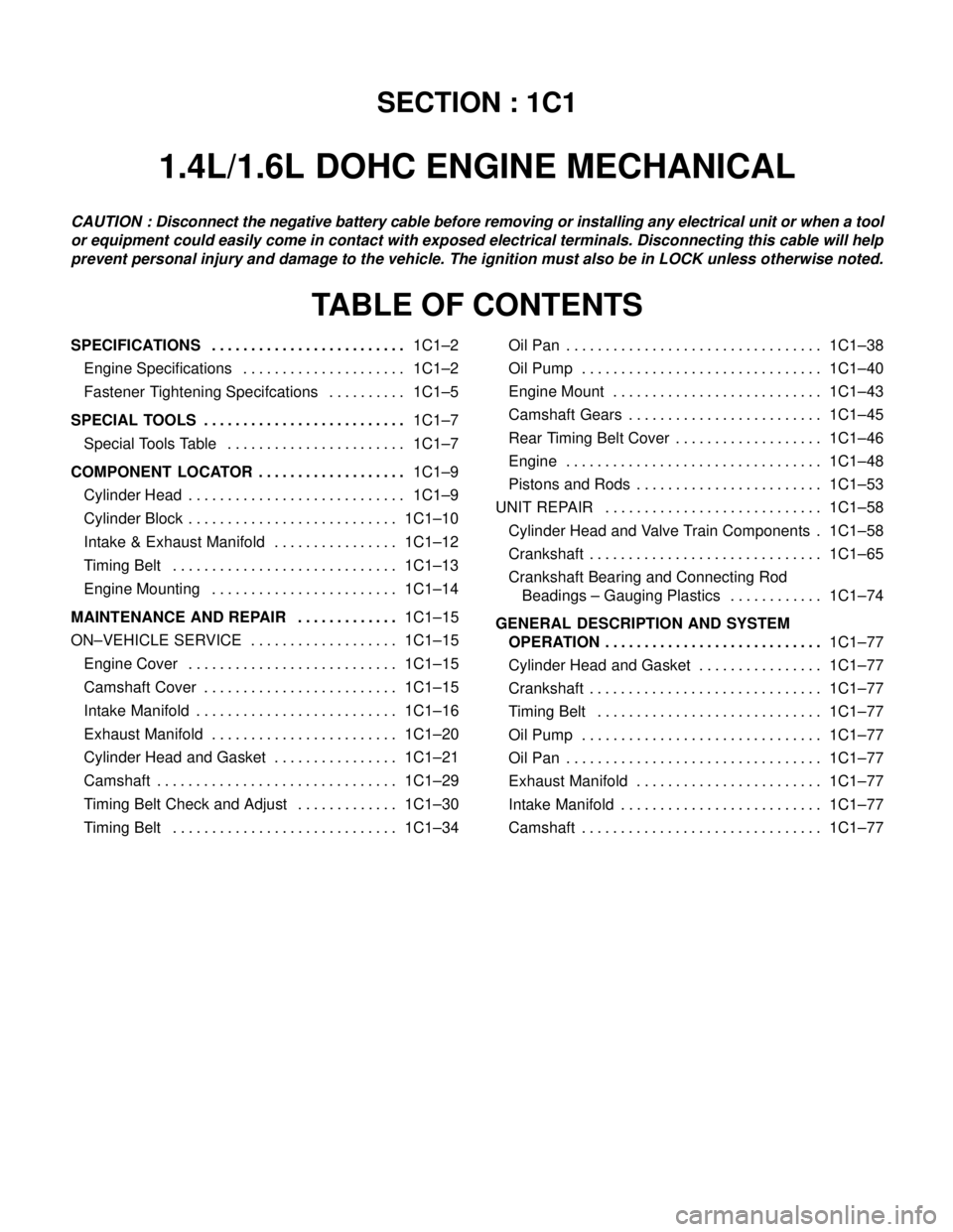
TABLE OF CONTENTS
SPECIFICATIONS1C1–2 . . . . . . . . . . . . . . . . . . . . . . . . .
Engine Specifications 1C1–2. . . . . . . . . . . . . . . . . . . . .
Fastener Tightening Specifcations 1C1–5. . . . . . . . . .
SPECIAL TOOLS1C1–7 . . . . . . . . . . . . . . . . . . . . . . . . . .
Special Tools Table 1C1–7. . . . . . . . . . . . . . . . . . . . . . .
COMPONENT LOCATOR1C1–9 . . . . . . . . . . . . . . . . . . .
Cylinder Head 1C1–9. . . . . . . . . . . . . . . . . . . . . . . . . . . .
Cylinder Block 1C1–10. . . . . . . . . . . . . . . . . . . . . . . . . . .
Intake & Exhaust Manifold 1C1–12. . . . . . . . . . . . . . . .
Timing Belt 1C1–13. . . . . . . . . . . . . . . . . . . . . . . . . . . . .
Engine Mounting 1C1–14. . . . . . . . . . . . . . . . . . . . . . . .
MAINTENANCE AND REPAIR1C1–15 . . . . . . . . . . . . .
ON–VEHICLE SERVICE 1C1–15. . . . . . . . . . . . . . . . . . .
Engine Cover 1C1–15. . . . . . . . . . . . . . . . . . . . . . . . . . .
Camshaft Cover 1C1–15. . . . . . . . . . . . . . . . . . . . . . . . .
Intake Manifold 1C1–16. . . . . . . . . . . . . . . . . . . . . . . . . .
Exhaust Manifold 1C1–20. . . . . . . . . . . . . . . . . . . . . . . .
Cylinder Head and Gasket 1C1–21. . . . . . . . . . . . . . . .
Camshaft 1C1–29. . . . . . . . . . . . . . . . . . . . . . . . . . . . . . .
Timing Belt Check and Adjust 1C1–30. . . . . . . . . . . . .
Timing Belt 1C1–34. . . . . . . . . . . . . . . . . . . . . . . . . . . . . Oil Pan 1C1–38. . . . . . . . . . . . . . . . . . . . . . . . . . . . . . . . .
Oil Pump 1C1–40. . . . . . . . . . . . . . . . . . . . . . . . . . . . . . .
Engine Mount 1C1–43. . . . . . . . . . . . . . . . . . . . . . . . . . .
Camshaft Gears 1C1–45. . . . . . . . . . . . . . . . . . . . . . . . .
Rear Timing Belt Cover 1C1–46. . . . . . . . . . . . . . . . . . .
Engine 1C1–48. . . . . . . . . . . . . . . . . . . . . . . . . . . . . . . . .
Pistons and Rods 1C1–53. . . . . . . . . . . . . . . . . . . . . . . .
UNIT REPAIR 1C1–58. . . . . . . . . . . . . . . . . . . . . . . . . . . .
Cylinder Head and Valve Train Components 1C1–58.
Crankshaft 1C1–65. . . . . . . . . . . . . . . . . . . . . . . . . . . . . .
Crankshaft Bearing and Connecting Rod
Beadings – Gauging Plastics 1C1–74. . . . . . . . . . . .
GENERAL DESCRIPTION AND SYSTEM
OPERATION1C1–77 . . . . . . . . . . . . . . . . . . . . . . . . . . . .
Cylinder Head and Gasket 1C1–77. . . . . . . . . . . . . . . .
Crankshaft 1C1–77. . . . . . . . . . . . . . . . . . . . . . . . . . . . . .
Timing Belt 1C1–77. . . . . . . . . . . . . . . . . . . . . . . . . . . . .
Oil Pump 1C1–77. . . . . . . . . . . . . . . . . . . . . . . . . . . . . . .
Oil Pan 1C1–77. . . . . . . . . . . . . . . . . . . . . . . . . . . . . . . . .
Exhaust Manifold 1C1–77. . . . . . . . . . . . . . . . . . . . . . . .
Intake Manifold 1C1–77. . . . . . . . . . . . . . . . . . . . . . . . . .
Camshaft 1C1–77. . . . . . . . . . . . . . . . . . . . . . . . . . . . . . .
Page 46 of 2643
1.4L/1.6L DOHC ENGINE MECHANICAL 1C1 – 3
DAEWOO V–121 BL4
ApplicationDescription (Manual and Automatic)
1.4L DOHC1.6L DOHC
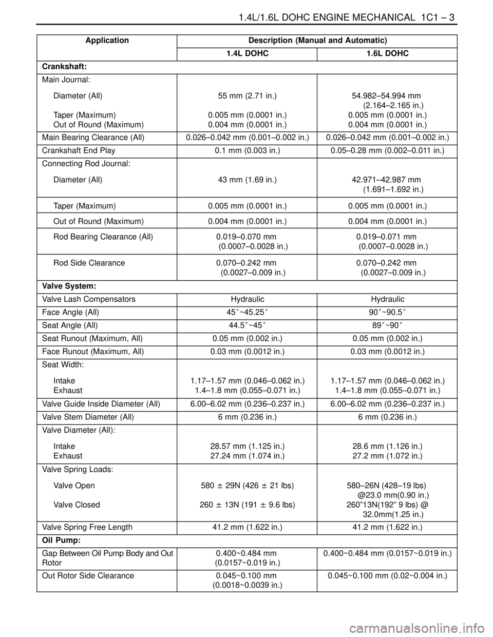
Crankshaft:
Main Journal:
Diameter (All)
Taper (Maximum)
Out of Round (Maximum)55 mm (2.71 in.)
0.005 mm (0.0001 in.)
0.004 mm (0.0001 in.)54.982–54.994 mm
(2.164–2.165 in.)
0.005 mm (0.0001 in.)
0.004 mm (0.0001 in.)
Main Bearing Clearance (All)0.026–0.042 mm (0.001–0.002 in.)0.026–0.042 mm (0.001–0.002 in.)
Crankshaft End Play0.1 mm (0.003 in.)0.05–0.28 mm (0.002–0.011 in.)
Connecting Rod Journal:
Diameter (All)43 mm (1.69 in.)
42.971–42.987 mm
(1.691–1.692 in.)
Taper (Maximum)0.005 mm (0.0001 in.)0.005 mm (0.0001 in.)
Out of Round (Maximum)0.004 mm (0.0001 in.)0.004 mm (0.0001 in.)
Rod Bearing Clearance (All)0.019–0.070 mm
(0.0007–0.0028 in.)0.019–0.071 mm
(0.0007–0.0028 in.)
Rod Side Clearance0.070–0.242 mm
(0.0027–0.009 in.)0.070–0.242 mm
(0.0027–0.009 in.)
Valve System:
Valve Lash CompensatorsHydraulicHydraulic
Face Angle (All)45°~45.25°90°~90.5°
Seat Angle (All)44.5°~45°89°~90°
Seat Runout (Maximum, All)0.05 mm (0.002 in.)0.05 mm (0.002 in.)
Face Runout (Maximum, All)0.03 mm (0.0012 in.)0.03 mm (0.0012 in.)
Seat Width:
Intake
Exhaust1.17–1.57 mm (0.046–0.062 in.)
1.4–1.8 mm (0.055–0.071 in.)1.17–1.57 mm (0.046–0.062 in.)
1.4–1.8 mm (0.055–0.071 in.)
Valve Guide Inside Diameter (All)6.00–6.02 mm (0.236–0.237 in.)6.00–6.02 mm (0.236–0.237 in.)
Valve Stem Diameter (All)6 mm (0.236 in.)6 mm (0.236 in.)
Valve Diameter (All):
Intake
Exhaust28.57 mm (1.125 in.)
27.24 mm (1.074 in.)28.6 mm (1.126 in.)
27.2 mm (1.072 in.)
Valve Spring Loads:
Valve Open
Valve Closed580 ± 29N (426 ± 21 lbs)
260 ± 13N (191 ± 9.6 lbs)580–26N (428–19 lbs)
@23.0 mm(0.90 in.)
260”13N(192” 9 lbs) @
32.0mm(1.25 in.)
Valve Spring Free Length41.2 mm (1.622 in.)41.2 mm (1.622 in.)
Oil Pump:
Gap Between Oil Pump Body and Out
Rotor0.400~0.484 mm
(0.0157~0.019 in.)0.400~0.484 mm (0.0157~0.019 in.)
Out Rotor Side Clearance0.045~0.100 mm
(0.0018~0.0039 in.)0.045~0.100 mm (0.02~0.004 in.)
Page 48 of 2643

1.4L/1.6L DOHC ENGINE MECHANICAL 1C1 – 5
DAEWOO V–121 BL4
FASTENER TIGHTENING SPECIFCATIONS
ApplicationNSmLb–FtLb–In
Air Cleaner Housing Bolts10–89
Camshaft Cap Bolts1612–
Camshaft Cover Nuts10–89
Connecting Rod Bearing Cap Bolts25
+ 30° + 15°18
+ 30° + 15°–
Coolant Temperature Sensor2015–
Crankshaft Bearing Cap Bolts50
+ 45° + 15°37
+ 45°+ 15°–
Crankshaft Cover Nuts5~8–44~71
Crankshaft Pulley Bolt95 NSm
+ 30° + 15°––
Cylinder Head Bolts (Cylinder Head Mounting Bolts)25 + 70°
+ 70° + 50°18 + 70°
+ 70° + 50°–
Direct Ignition System Coil Mounting Bolts10–89
Direct Ignition System Coil Mounting Bracket Bolts10–89
Engine Mount Attaching Bolts3022–
Engine Mount Bracket Attaching Bolts/Nuts5037–
Exhaust Camshaft Gear Bolt67.549–
Exhaust Flex Pipe–to–Catalytic Converter or Connecting Pipe
Retaining Nut3526–
Exhaust Flex Pipe–to–Exhaust Manifold Retaining Nuts3526–
Exhaust Gas Recirculation Valve Adapter Bolts2518–
Exhaust Manifold Heat Shield Bolts1511–
Exhaust Manifold Retaining Nuts2518–
Flexible Plate Bolts6044–
Flexible Plate Inspection Cover Bolts10–89
Flywheel Bolts35
+ 30° + 15°25
+ 30° + 15°–
Flywheel Inspection Cover Bolts12–106
Front Timing Belt Cover Bolts (Upper and Lower)10–89
Fuel Rail Assembly Retaining Bolts2518–
Fuel Rail Retaining Bolts2518–
Generator Upper Retaining Bolt2015–
Intake Camshaft Gear Bolt67.549–
Intake Manifold Retaining Bolts/Nuts2518–
Intake Manifold Support Bracket Lower Bolt2518–
Intake Manifold Support Bracket Upper Bolts2518–
Lower Front Timing Belt Cover Bolts10–89
Oil Pan Flange Bolts7555–
Oil Pan Retaining Bolts10–89
Oil Pan Drain Plug3526–
OIl Pressure Switch4030–
Page 54 of 2643

1.4L/1.6L DOHC ENGINE MECHANICAL 1C1 – 11
DAEWOO V–121 BL4
1. Piston Ring Set
2. Piston
3. Piston Pin
4. Connecting Rod
5. Connecting Rod Bearing Set
6. Oil Level Gauge Stick
7. Gauge Stic Tube
8. Sleeve
9. Clutch Housing Sleeve
10. Cylinder Block
11. Plug
12. Gap
13. Bypass Valve
14. Connecting Piece
15. Oil Filter
16. Oil Pump Body Gasket
17. Water Inlet Neck
18. Knock Sensor
19. Fly Wheel (M/T)
20. Flexible Plate (A/T)
21. Shaft Seal Ring
22. Crank Shaft Upper Bearing Set
23. Crank Shaft24. Crank Shaft Lower Bearing Set
25. Transmitter Disc
26. Crankshaft Bearing Cap
27. Oil Pan
28. Threaded Ring
29. Washer
30. Oil Pan Drain Plug
31. Oil Pump
32. Oil Pump Cover
33. Oil Pump Inner Rotor
34. Oil Pump Outer Rotor
35. Oil Pump Plug
36. Shaft Sealing
37. Pressure Relief Valve Plunger
38. Relief Valve Spring
39. Sealing
40. Relief Valve
41. Oil Pressure Switch
42. Sleeve
43. Oil Suction Pipe Bracket
44. Oil Suction Pipe
45. Sealing
Page 96 of 2643
1.4L/1.6L DOHC ENGINE MECHANICAL 1C1 – 53
DAEWOO V–121 BL4
39. Connect the lower radiator hose to the coolant pipe.
40. Connect the upper radiator hose to the thermostat
housing.
41. Connect the surge tank coolant hose to the radia-
tor.
42. Connect the heater inlet hose to the cylinder head.
43. Connect the heater outlet hose to the coolant pipe.
44. Connect the coolant surge tank hose to the coolant
pipe.
45. Connect the surge tank coolant hose to the throttle
body.
46. Connect the throttle cable to the throttle body and
the intake manifold bracket.
47. Install the fuel pump fuse.
48. Connect the negative battery cable.
49. Refill the engine crankcase with engine oil.
50. Refill the engine coolant system. Refer to Section
1D, Engine Cooling.
51. Bleed the power steering system. Refer to Section
6A, Power Steering System.
52. Refill the A/C refrigerant system, if equipped. Refer
to Section 7B, Manual Control Heating, Ventilation,
and Air Conditioning System.
53. Install the hood. Refer to Section 9R, Body Front
End.
PISTONS AND RODS
Tools Required
KM–427 Piston Pin Service Set
KM 470–B Angular Torque Gauge
Removal Procedure
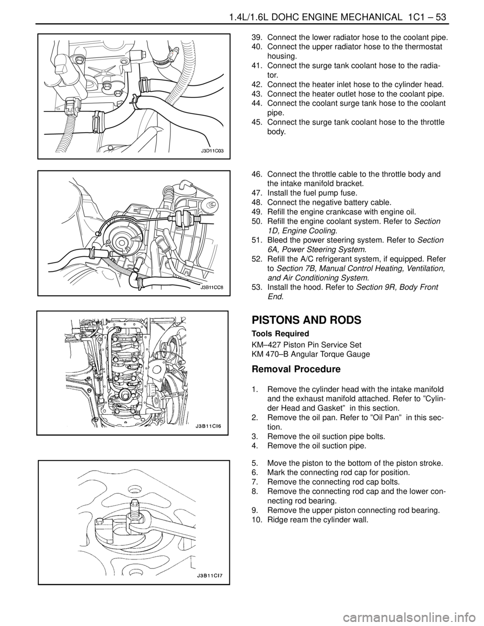
1. Remove the cylinder head with the intake manifold
and the exhaust manifold attached. Refer to ”Cylin-
der Head and Gasket” in this section.
2. Remove the oil pan. Refer to ”Oil Pan” in this sec-
tion.
3. Remove the oil suction pipe bolts.
4. Remove the oil suction pipe.
5. Move the piston to the bottom of the piston stroke.
6. Mark the connecting rod cap for position.
7. Remove the connecting rod cap bolts.
8. Remove the connecting rod cap and the lower con-
necting rod bearing.
9. Remove the upper piston connecting rod bearing.
10. Ridge ream the cylinder wall.
Page 97 of 2643
1C1 – 54I1.4L/1.6L DOHC ENGINE MECHANICAL
DAEWOO V–121 BL4
CAUTION : Use care when handling the piston. Worn
piston rings are sharp and may cause injury.
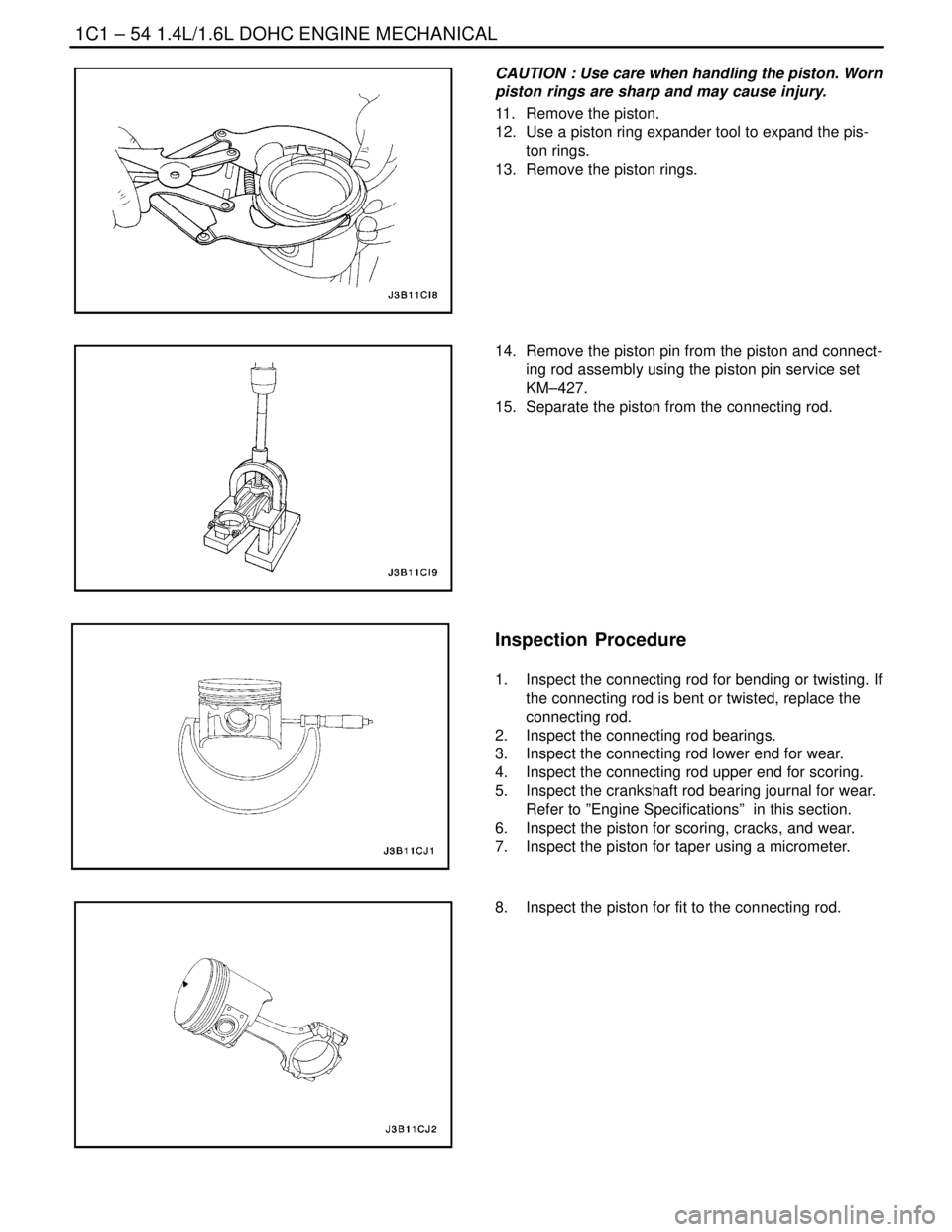
11. Remove the piston.
12. Use a piston ring expander tool to expand the pis-
ton rings.
13. Remove the piston rings.
14. Remove the piston pin from the piston and connect-
ing rod assembly using the piston pin service set
KM–427.
15. Separate the piston from the connecting rod.
Inspection Procedure
1. Inspect the connecting rod for bending or twisting. If
the connecting rod is bent or twisted, replace the
connecting rod.
2. Inspect the connecting rod bearings.
3. Inspect the connecting rod lower end for wear.
4. Inspect the connecting rod upper end for scoring.
5. Inspect the crankshaft rod bearing journal for wear.
Refer to ”Engine Specifications” in this section.
6. Inspect the piston for scoring, cracks, and wear.
7. Inspect the piston for taper using a micrometer.
8. Inspect the piston for fit to the connecting rod.
Page 98 of 2643
1.4L/1.6L DOHC ENGINE MECHANICAL 1C1 – 55
DAEWOO V–121 BL4
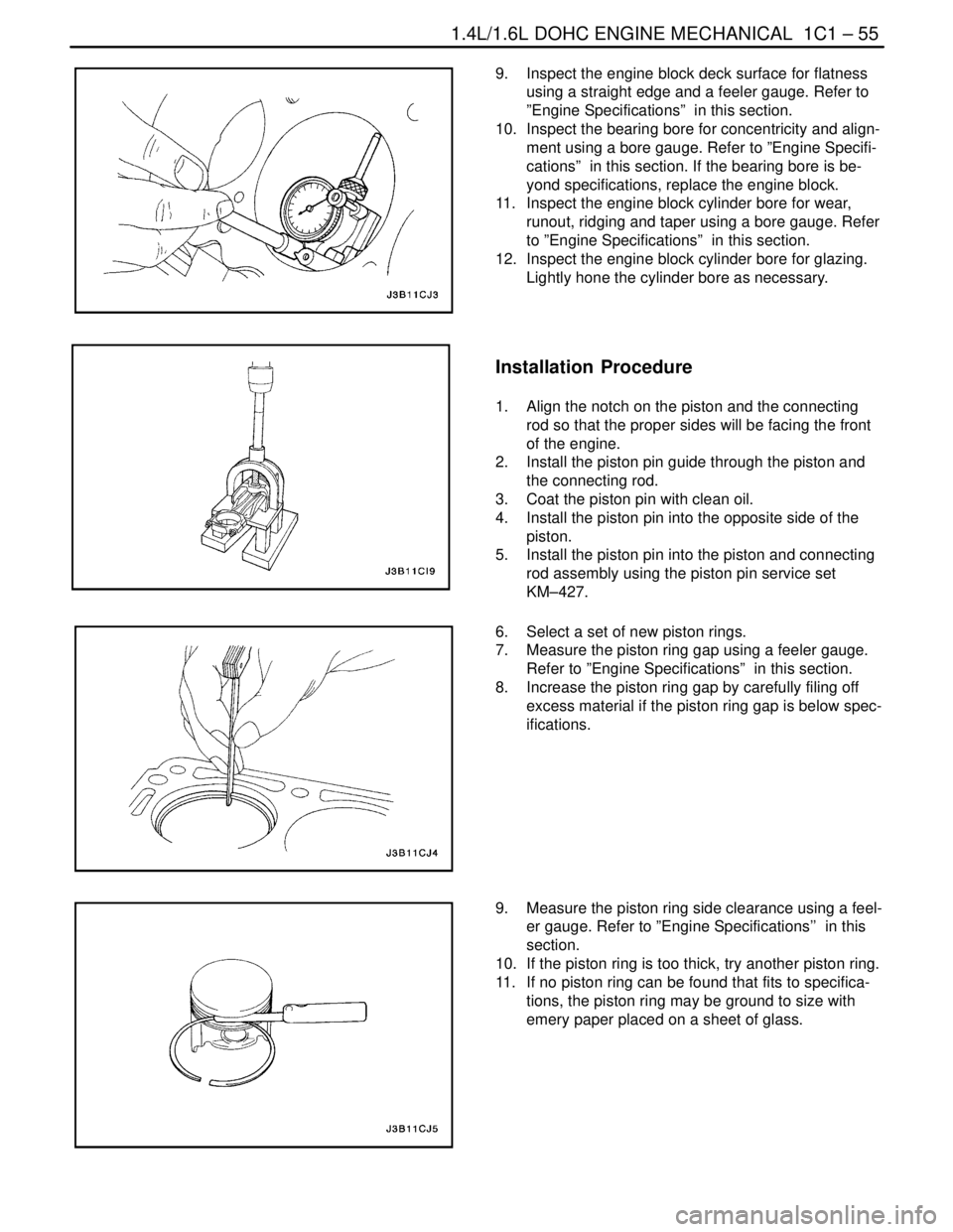
9. Inspect the engine block deck surface for flatness
using a straight edge and a feeler gauge. Refer to
”Engine Specifications” in this section.
10. Inspect the bearing bore for concentricity and align-
ment using a bore gauge. Refer to ”Engine Specifi-
cations” in this section. If the bearing bore is be-
yond specifications, replace the engine block.
11. Inspect the engine block cylinder bore for wear,
runout, ridging and taper using a bore gauge. Refer
to ”Engine Specifications” in this section.
12. Inspect the engine block cylinder bore for glazing.
Lightly hone the cylinder bore as necessary.
Installation Procedure
1. Align the notch on the piston and the connecting
rod so that the proper sides will be facing the front
of the engine.
2. Install the piston pin guide through the piston and
the connecting rod.
3. Coat the piston pin with clean oil.
4. Install the piston pin into the opposite side of the
piston.
5. Install the piston pin into the piston and connecting
rod assembly using the piston pin service set
KM–427.
6. Select a set of new piston rings.
7. Measure the piston ring gap using a feeler gauge.
Refer to ”Engine Specifications” in this section.
8. Increase the piston ring gap by carefully filing off
excess material if the piston ring gap is below spec-
ifications.
9. Measure the piston ring side clearance using a feel-
er gauge. Refer to ”Engine Specifications’’ in this
section.
10. If the piston ring is too thick, try another piston ring.
11. If no piston ring can be found that fits to specifica-
tions, the piston ring may be ground to size with
emery paper placed on a sheet of glass.
Page 99 of 2643
1C1 – 56I1.4L/1.6L DOHC ENGINE MECHANICAL
DAEWOO V–121 BL4
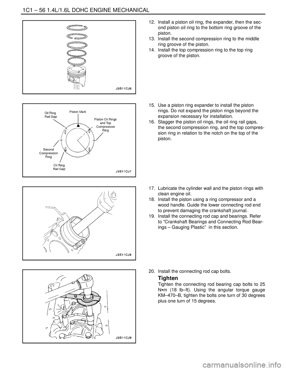
12. Install a piston oil ring, the expander, then the sec-
ond piston oil ring to the bottom ring groove of the
piston.
13. Install the second compression ring to the middle
ring groove of the piston.
14. Install the top compression ring to the top ring
groove of the piston.
15. Use a piston ring expander to install the piston
rings. Do not expand the piston rings beyond the
expansion necessary for installation.
16. Stagger the piston oil rings, the oil ring rail gaps,
the second compression ring, and the top compres-
sion ring in relation to the notch on the top of the
piston.
17. Lubricate the cylinder wall and the piston rings with
clean engine oil.
18. Install the piston using a ring compressor and a
wood handle. Guide the lower connecting rod end
to prevent damaging the crankshaft journal.
19. Install the connecting rod cap and bearings. Refer
to ”Crankshaft Bearings and Connecting Rod Bear-
ings – Gauging Plastic” in this section.
20. Install the connecting rod cap bolts.
Tighten
Tighten the connecting rod bearing cap bolts to 25
NSm (18 lb–ft). Using the angular torque gauge
KM–470–B, tighten the bolts one turn of 30 degrees
plus one turn of 15 degrees.