2004 DAEWOO LACETTI Jack point
[x] Cancel search: Jack pointPage 213 of 2643

1D – 18IENGINE COOLING
DAEWOO V–121 BL4
GENERAL DESCRIPTION
AND SYSTEM OPERATION
GENERAL DESCRIPTION
The cooling system maintains the engine temperature at
an efficient level during all engine operating conditions.
When the engine is cold, the cooling system cools the en-
gine slowly or not at all. This slow cooling of the engine al-
lows the engine to warm up quickly.
The cooling system includes a radiator and recovery sub-
system, cooling fans, a thermostat and housing, a coolant
pump, and a coolant pump drive belt. The timing belt
drives the coolant pump.
All components must function properly in order for the
cooling system to operate. The coolant pump draws the
coolant from the radiator. The coolant then circulates
through water jackets in the engine block, the intake man-
ifold, and the cylinder head. When the coolant reaches the
operating temperature of the thermostat, the thermostat
opens. The coolant then goes back to the radiator where
it cools.
This system directs some coolant through the hoses to the
heater core. This provides for heating and defrosting. The
surge tank is connected to the radiator to recover the cool-
ant displaced by expansion from the high temperatures.
The surge tank maintains the correct coolant level.
The cooling system for this vehicle has no radiator cap or
filler neck. The coolant is added to the cooling system
through the surge tank.
RADIATOR
This vehicle has a lightweight tube–and–fin aluminum ra-
diator. Plastic tanks are mounted on the right and the left
sides of the radiator core.
On vehicles equipped with automatic transaxles, the
transaxle fluid cooler lines run through the left radiator
tank. A radiator drain cock is on this radiator.
To drain the cooling system, open the drain cock.
SURGE TANK
The surge tank is a transparent plastic reservoir, similar to
the windshield washer reservoir.
The surge tank is connected to the radiator by a hose and
to the engine cooling system by another hose. As the ve-
hicle is driven, the engine coolant heats and expands. The
portion of the engine coolant displaced by this expansion
flows from the radiator and the engine into the surge tank.
The air trapped in the radiator and the engine is degassed
into the surge tank.When the engine stops, the engine coolant cools and con-
tracts. The displaced engine coolant is then drawn back
into the radiator and the engine. This keeps the radiator
filled with the coolant to the desired level at all times and
increases the cooling efficiency.
Maintain the coolant level between the MIN and the MAX
marks on the surge tank when the system is cold.
WATER PUMP
The belt–driven centrifugal water pump consists of an im-
peller, a drive shaft, and a belt pulley. The water pump is
mounted on the front of the transverse–mounted engine,
and is driven by the timing belt.
The impeller is supported by a completely sealed bearing.
The water pump is serviced as an assembly and, there-
fore, cannot be disassembled.
THERMOSTAT
A wax pellet–type thermostat controls the flow of the en-
gine coolant through the engine cooling system. The ther-
mostat is mounted in the thermostat housing to the front
of the cylinder head.
The thermostat stops the flow of the engine coolant from
the engine to the radiator in order to provide faster warm–
up, and to regulate the coolant temperature. The thermo-
stat remains closed while the engine coolant is cold, pre-
venting circulation of the engine coolant through the
radiator. At this point, the engine coolant is allowed to cir-
culate only throughout the heater core to warm it quickly
and evenly.
As the engine warms, the thermostat opens. This allows
the engine coolant to flow through the radiator, where the
heat is dissipated through the radiator. This opening and
closing of the thermostat permits enough engine coolant
to enter the radiator to keep the engine within proper en-
gine temperature operating limits.
The wax pellet in the thermostat is hermetically sealed in
a metal case. The wax element of the thermostat expands
when it is heated and contracts when it is cooled.
As the vehicle is driven and the engine warms, the engine
coolant temperature increases. When the engine coolant
reaches a specified temperature, the wax pellet element
in the thermostat expands and exerts pressure against the
metal case, forcing the valve open. This allows the engine
coolant to flow through the engine cooling system and cool
the engine.
As the wax pellet cools, the contraction allows a spring to
close the valve.
The thermostat begins to open at 87°C (189°F) and is fully
open at 102°C (216°F). The thermostat closes at 86°C
(187°F).
Page 1971 of 2643
STEERING WHEEL AND COLUMN 6E – 17
DAEWOO V–121 BL4
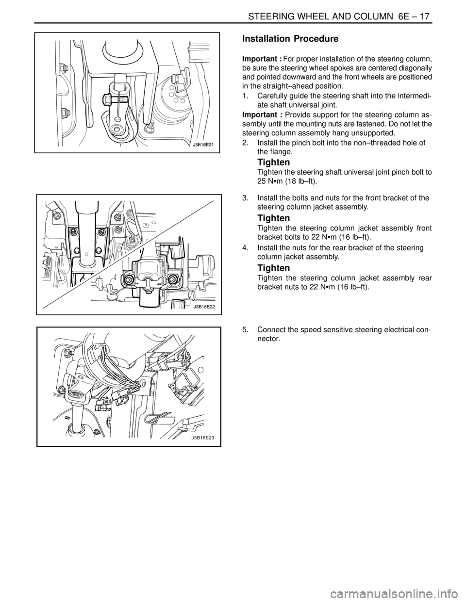
Installation Procedure
Important : For proper installation of the steering column,
be sure the steering wheel spokes are centered diagonally
and pointed downward and the front wheels are positioned
in the straight–ahead position.
1. Carefully guide the steering shaft into the intermedi-
ate shaft universal joint.
Important : Provide support for the steering column as-
sembly until the mounting nuts are fastened. Do not let the
steering column assembly hang unsupported.
2. Install the pinch bolt into the non–threaded hole of
the flange.
Tighten
Tighten the steering shaft universal joint pinch bolt to
25 NSm (18 lb–ft).
3. Install the bolts and nuts for the front bracket of the
steering column jacket assembly.
Tighten
Tighten the steering column jacket assembly front
bracket bolts to 22 NSm (16 lb–ft).
4. Install the nuts for the rear bracket of the steering
column jacket assembly.
Tighten
Tighten the steering column jacket assembly rear
bracket nuts to 22 NSm (16 lb–ft).
5. Connect the speed sensitive steering electrical con-
nector.
Page 2537 of 2643
NUBIRA/LACETTIFRONT 4–3
1–2. REPAIR PROCEDURE
1. Remove the related parts.
S Hood, radiator grill and front bumper.
S Head lamps and fender.
S Engine, radiator and related parts.
S Aircon condenser and related parts.
S Others.
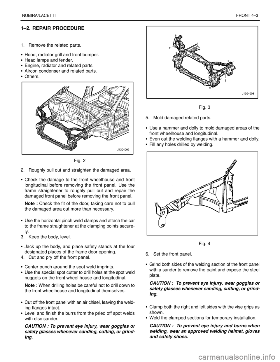
Fig. 2
2. Roughly pull out and straighten the damaged area.
S Check the damage to the front wheelhouse and front
longitudinal before removing the front panel. Use the
frame straightener to roughly pull out and repair the
damaged front panel before removing the front panel.
Note : Check the fit of the door, taking care not to pull
the damaged area out more than necessary.
S Use the horizontal pinch weld clamps and attach the car
to the frame straightener at the clamping points secure-
ly.
3. Keep the body, level.
S Jack up the body, and place safety stands at the four
designated places of the frame door opening.
4. Cut and pry off the front panel.
S Center punch around the spot weld imprints.
S Use the special spot cutter to drill holes at the spot weld
nuggets on the front wheel house and longitudinal.
Note : When drilling holes be careful not to drill down to
the front wheelhouse and longitudinal themselves.
S Cut off the front panel with an air chisel, leaving the weld-
ing flanges intact.
S Level and finish the burrs from the pried off spot welds
with disc sander.
CAUTION : To prevent eye injury, wear goggles or
safety glasses whenever sanding, cutting, or grind-
ing.
Fig. 3
5. Mold damaged related parts.
S Use a hammer and dolly to mold damaged areas of the
front wheelhouse and longitudinal.
S Even out the welding flanges with a hammer and dolly.
S Fill any holes drilled by welding.
Fig. 4
6. Set the front panel.
S Grind both sides of the welding section of the front panel
with a sander to remove the paint and expose the steel
plate.
CAUTION : To prevent eye injury, wear goggles or
safety glasses whenever sanding, cutting, or grind-
ing.
S Clamp both the right and left sides with the vise grips as
shown.
S Weld the clamped sections for temporary installation.
CAUTION : To prevent eye injury and burns when
welding, wear an approved welding helmet, gloves
and safety shoes.
Page 2545 of 2643
NUBIRA/LACETTIFRONT 4–11
3–2. REPAIR PROCEDURE
1. Remove the related parts.
S Parts to be removed when removing the front panel and
front wheelhouse.
S Parts on passenger side of dash panel lower which are
especially flammable.
S Instrument panel, wiring harness, related parts and oth-
ers.
Note : Remove according to part damaged.
2. Roughly pull out and straighten the damaged area to
approximately the original shape.
S Attach the car to the frame straightener by tightening the
underbody clamps at the horizontal pinch weld points.
S Before cutting off the damaged sections, pull them out
so that they are restored to the original shape.
S Roughly cut off the front longitudinal according to the ex-
tent of damage before roughly pulling out the damage
makes repair of the related parts difficult.
S Do not pull out more than necessary.
Note : Check the condition of the door and hinges.
3. Peel off the undercoat and sealer.
S Heat the undercoat and sealer at the welding areas of
the damaged parts with a gas torch and peel off the un-
dercoat and sealer with a steel spatula.
CAUTION : Be careful not to burn the fittings inside
the passenger compartment when heating.
4. Cut and pry off the front longitudinal.
Note : It’s not necessary to separate the wheelhouse
from the front longitudinal if the wheelhouse is to be re-
placed also.
S Center punch around the spot weld imprints on the
wheelhouse and other related parts.
S Use the special spot cutter to drill holes at the spot weld
nuggets on the center punched areas.
S Cut off the front longitudinal with an air chisel, leaving the
welding flanges intact.
S Level and finish the burrs from the pried off spot welds
with a disc sander.
CAUTION : To prevent eye injury, wear goggles or
safety glasses whenever sanding, cutting, or grind-
ing.
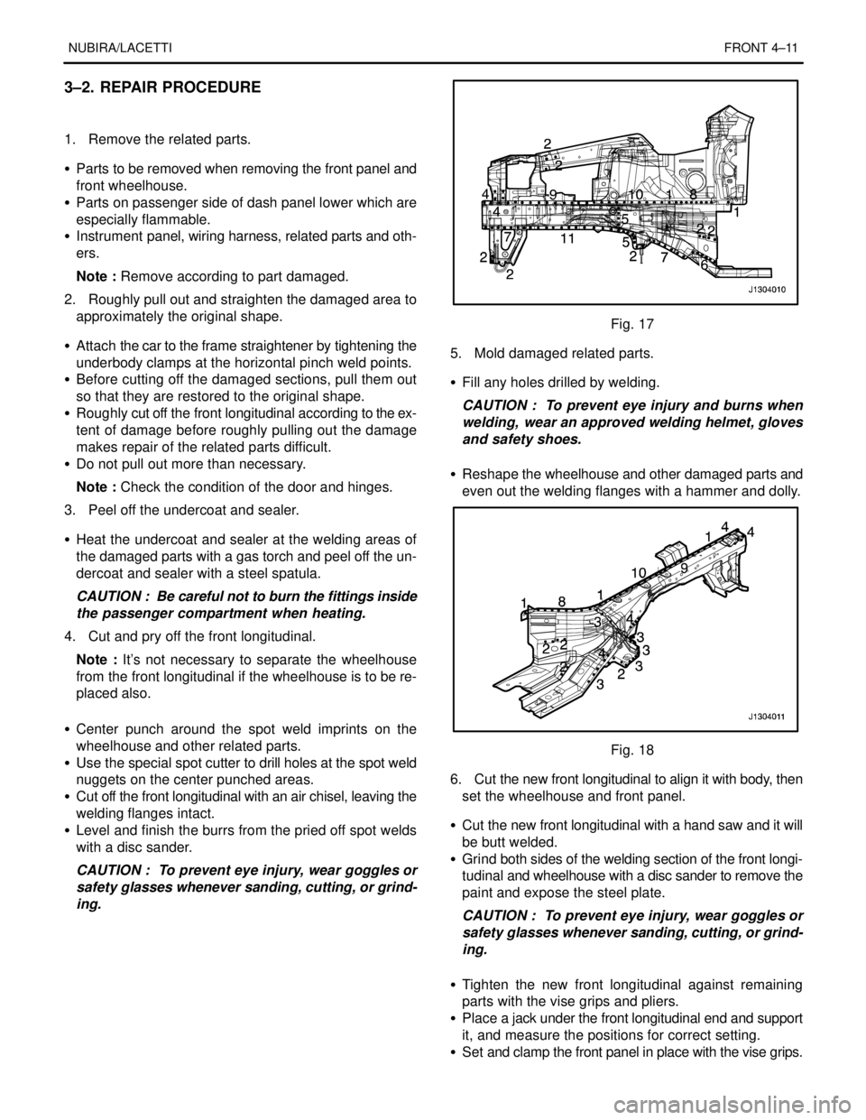
Fig. 17
5. Mold damaged related parts.
S Fill any holes drilled by welding.
CAUTION : To prevent eye injury and burns when
welding, wear an approved welding helmet, gloves
and safety shoes.
S Reshape the wheelhouse and other damaged parts and
even out the welding flanges with a hammer and dolly.
Fig. 18
6. Cut the new front longitudinal to align it with body, then
set the wheelhouse and front panel.
S Cut the new front longitudinal with a hand saw and it will
be butt welded.
S Grind both sides of the welding section of the front longi-
tudinal and wheelhouse with a disc sander to remove the
paint and expose the steel plate.
CAUTION : To prevent eye injury, wear goggles or
safety glasses whenever sanding, cutting, or grind-
ing.
S Tighten the new front longitudinal against remaining
parts with the vise grips and pliers.
S Place a jack under the front longitudinal end and support
it, and measure the positions for correct setting.
S Set and clamp the front panel in place with the vise grips.
Page 2559 of 2643
NUBIRA/LACETTI ROOF, BACK PANEL AND REAR FLOOR PANEL 5–7
2–2. REPAIR PROCEDURE
1. Remove the related parts.
S Rear and trunk trims
S Trunk lid lock and related parts.
S Rear combination lamps and wiring harness.
S Rear bumper and related parts.
S Other related parts.
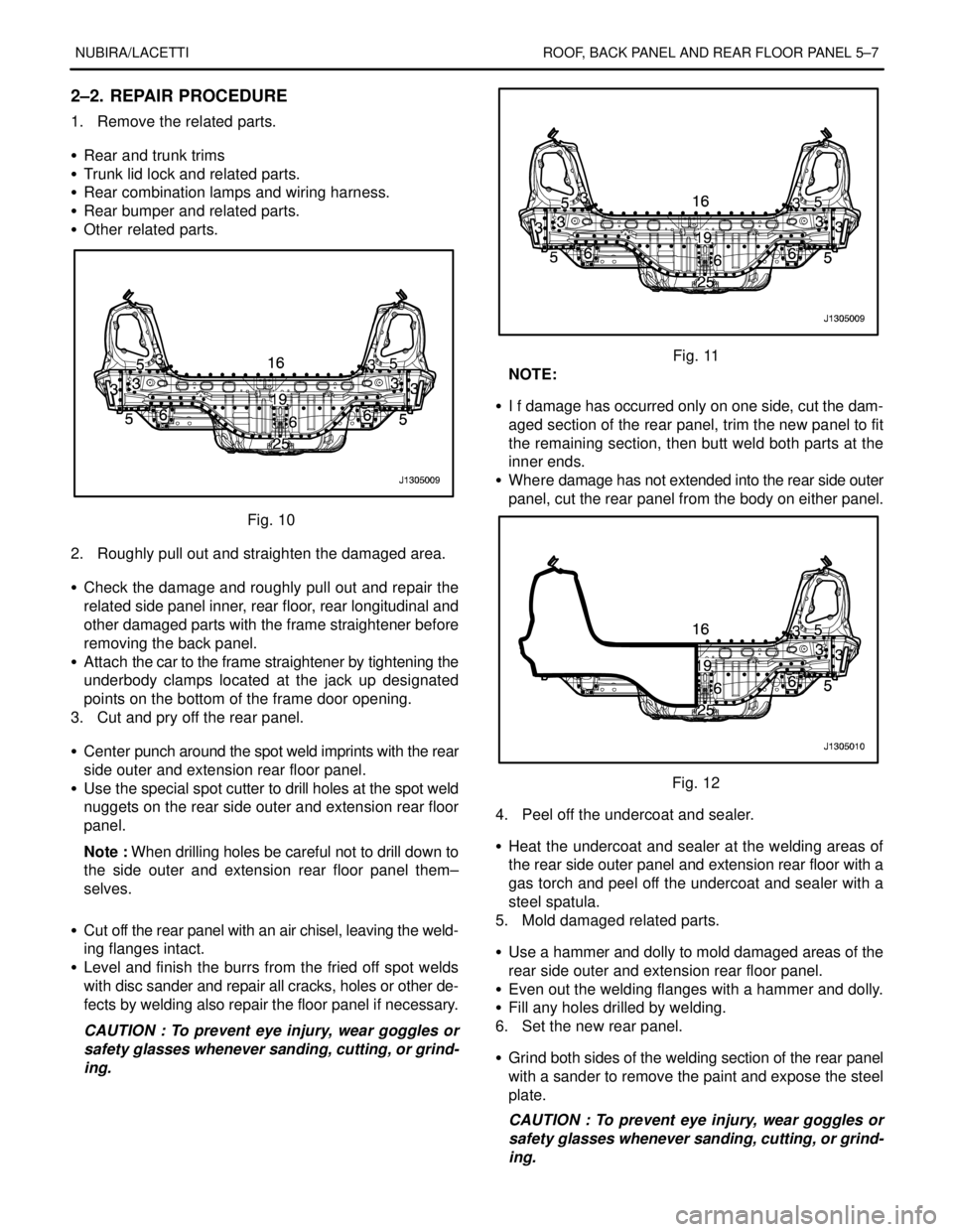
Fig. 10
2. Roughly pull out and straighten the damaged area.
S Check the damage and roughly pull out and repair the
related side panel inner, rear floor, rear longitudinal and
other damaged parts with the frame straightener before
removing the back panel.
S Attach the car to the frame straightener by tightening the
underbody clamps located at the jack up designated
points on the bottom of the frame door opening.
3. Cut and pry off the rear panel.
S Center punch around the spot weld imprints with the rear
side outer and extension rear floor panel.
S Use the special spot cutter to drill holes at the spot weld
nuggets on the rear side outer and extension rear floor
panel.
Note : When drilling holes be careful not to drill down to
the side outer and extension rear floor panel them–
selves.
S Cut off the rear panel with an air chisel, leaving the weld-
ing flanges intact.
S Level and finish the burrs from the fried off spot welds
with disc sander and repair all cracks, holes or other de-
fects by welding also repair the floor panel if necessary.
CAUTION : To prevent eye injury, wear goggles or
safety glasses whenever sanding, cutting, or grind-
ing.
Fig. 11
NOTE:
S I f damage has occurred only on one side, cut the dam-
aged section of the rear panel, trim the new panel to fit
the remaining section, then butt weld both parts at the
inner ends.
S Where damage has not extended into the rear side outer
panel, cut the rear panel from the body on either panel.
Fig. 12
4. Peel off the undercoat and sealer.
S Heat the undercoat and sealer at the welding areas of
the rear side outer panel and extension rear floor with a
gas torch and peel off the undercoat and sealer with a
steel spatula.
5. Mold damaged related parts.
S Use a hammer and dolly to mold damaged areas of the
rear side outer and extension rear floor panel.
S Even out the welding flanges with a hammer and dolly.
S Fill any holes drilled by welding.
6. Set the new rear panel.
S Grind both sides of the welding section of the rear panel
with a sander to remove the paint and expose the steel
plate.
CAUTION : To prevent eye injury, wear goggles or
safety glasses whenever sanding, cutting, or grind-
ing.
Page 2563 of 2643
NUBIRA/LACETTI ROOF, BACK PANEL AND REAR FLOOR PANEL 5–11
3–2. REPAIR PROCEDURE
1. Remove the related parts.
S Parts to be removed when removing the back panel.
S Rear seat belt and rear seat.
S Muffler, fuel tank and related parts.
S Chassis parts.
S Other related parts.
CAUTION : Do not smoke while working near the
fuel system. Keep open flame away from the fuel
system. If necessary, remove the fuel tank and off
lines.
2. Roughly pull out and straighten the damaged area.
S Check the damage and roughly pull out and re pair the
related back panel, side panel, wheel house inner, rear
longitudinal and other damaged parts with the frame
straightener before remov ing the extension rear floor
panel, rear floor pane and back panel.
S Attach the car to the frame straightener by tightening the
underbody clamps located at the jack up designated
points on the bottom of the frame door opening.
Note : Measure in reference to the dimensions on the
body repair chart.
3. Cut and pry off the back panel.
S The back panel to be cut and pried off when removing
the back panel.
4. Cut and pry off the rear floor and extension rear floor
panel.
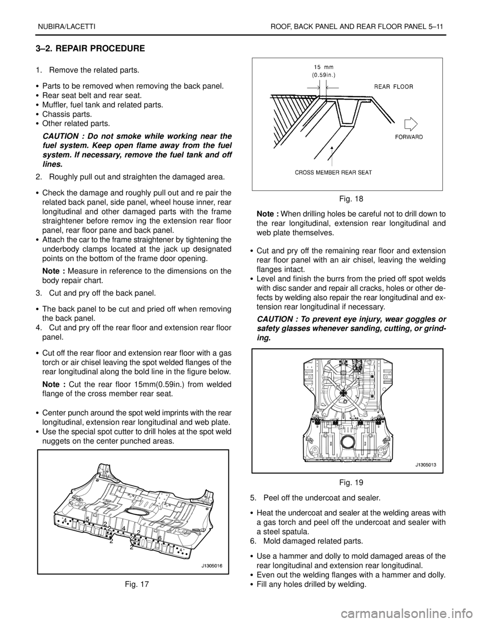
S Cut off the rear floor and extension rear floor with a gas
torch or air chisel leaving the spot welded flanges of the
rear longitudinal along the bold line in the figure below.
Note : Cut the rear floor 15mm(0.59in.) from welded
flange of the cross member rear seat.
S Center punch around the spot weld imprints with the rear
longitudinal, extension rear longitudinal and web plate.
S Use the special spot cutter to drill holes at the spot weld
nuggets on the center punched areas.
Fig. 17
Fig. 18
Note : When drilling holes be careful not to drill down to
the rear longitudinal, extension rear longitudinal and
web plate themselves.
S Cut and pry off the remaining rear floor and extension
rear floor panel with an air chisel, leaving the welding
flanges intact.
S Level and finish the burrs from the pried off spot welds
with disc sander and repair all cracks, holes or other de-
fects by welding also repair the rear longitudinal and ex-
tension rear longitudinal if necessary.
CAUTION : To prevent eye injury, wear goggles or
safety glasses whenever sanding, cutting, or grind-
ing.
Fig. 19
5. Peel off the undercoat and sealer.
S Heat the undercoat and sealer at the welding areas with
a gas torch and peel off the undercoat and sealer with
a steel spatula.
6. Mold damaged related parts.
S Use a hammer and dolly to mold damaged areas of the
rear longitudinal and extension rear longitudinal.
S Even out the welding flanges with a hammer and dolly.
S Fill any holes drilled by welding.