2004 DAEWOO LACETTI Pressure valve
[x] Cancel search: Pressure valvePage 131 of 2643

1.8L DOHC ENGINE MECHANICAL 1C2 – 11
DAEWOO V–121 BL4
1. Connecting Rod
2. Bearing Set
3. Connecting Rod Bolt
4. Piston Ring Set
5. Piston Pin
6. Piston
7. Engine Block
8. Sleeve
9. Water Jacket Cap
10. Bolt (Manual Transaxle)
11. Flywheel (Manual Transaxle)
12. Flexible Plate (Automatic Transaxle)
13. Bolt (Automatic Transaxle)
14. Clamp
15. Hose
16. Clamp
17. Engine Ventilation Pipe
18. Bolt
19. Gasket
20. Needle Sleeve
21. Crankshaft Rear Seal
22. Crankshaft
23. Transmitter Disk
24. Bolt
25. Oil Pan Scraper
26. Oil Pan
27. Drain Plug
28. Washer
29. Bolt
30. Sleeve
31. Gasket
32. Bolt
33. Oil Pump Cover
34. Ring Gear
35. Gear
36. Oil Pressure Switch
37. Washer
38. Washer
39. Oil Duct Outlet Plug
40. Connecting Piece
41. Seal Ring
42. Oil Filter43. Bypass Valve
44. Pressure Relief Valve Plunger
45. Pressure Relief Valve Spring
46. Seal Ring
47. Pressure Relief Valve Plug
48. Seal Ring
49. Bolt
50. Oil Suction Pipe
51. Bolt
52. Rear Timing Belt Cover
53. Bolt
54. Special Bolt
55. Idler Pulley
56. Stud
57. Nut
58. Bolt
59. Tensioner
60. Bolt
61. Thrust Inner Washer
62. Woodruff Key
63. Crankshaft Gear
64. Thrust Outer Washer
65. Bolt
66. Camshaft Drive Belt
67. Gasket
68. Front Timing Belt Cover
69. Bolt
70. Bushing Plug
71. Bushing
72. Oil Gallery Plug
73. Bolt
74. Water Pump
75. Seal Ring
76. Crankshaft Position Sensor
77. Bolt
78. Knock Sensor*
79. Bolt
80. Bolt
81. Crankshaft Bearing Bridge
* : 2.0L DOHC Engine
Page 159 of 2643
1.8L DOHC ENGINE MECHANICAL 1C2 – 39
DAEWOO V–121 BL4
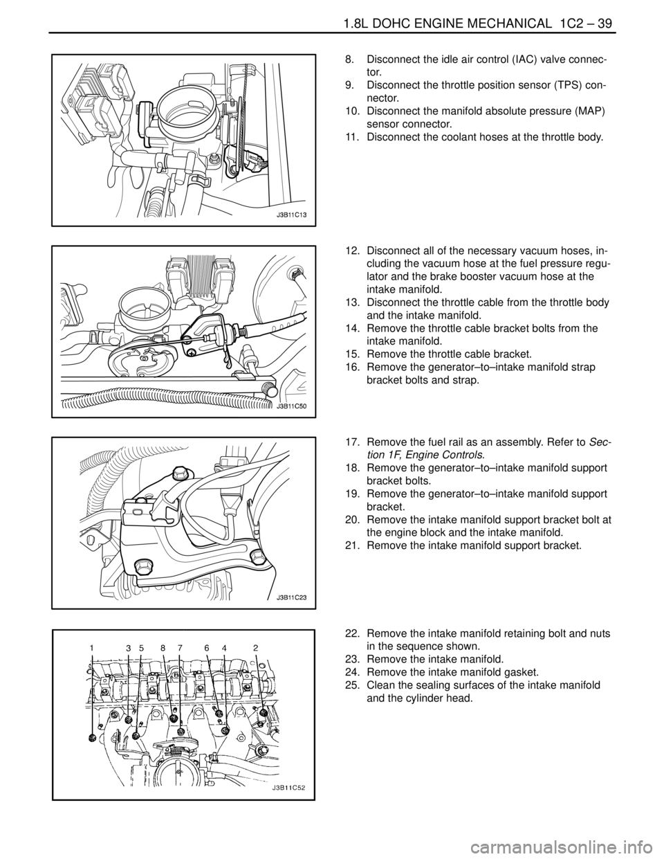
8. Disconnect the idle air control (IAC) valve connec-
tor.
9. Disconnect the throttle position sensor (TPS) con-
nector.
10. Disconnect the manifold absolute pressure (MAP)
sensor connector.
11. Disconnect the coolant hoses at the throttle body.
12. Disconnect all of the necessary vacuum hoses, in-
cluding the vacuum hose at the fuel pressure regu-
lator and the brake booster vacuum hose at the
intake manifold.
13. Disconnect the throttle cable from the throttle body
and the intake manifold.
14. Remove the throttle cable bracket bolts from the
intake manifold.
15. Remove the throttle cable bracket.
16. Remove the generator–to–intake manifold strap
bracket bolts and strap.
17. Remove the fuel rail as an assembly. Refer to Sec-
tion 1F, Engine Controls.
18. Remove the generator–to–intake manifold support
bracket bolts.
19. Remove the generator–to–intake manifold support
bracket.
20. Remove the intake manifold support bracket bolt at
the engine block and the intake manifold.
21. Remove the intake manifold support bracket.
22. Remove the intake manifold retaining bolt and nuts
in the sequence shown.
23. Remove the intake manifold.
24. Remove the intake manifold gasket.
25. Clean the sealing surfaces of the intake manifold
and the cylinder head.
Page 170 of 2643
1C2 – 50I1.8L DOHC ENGINE MECHANICAL
DAEWOO V–121 BL4
18. Install the exhaust flex pipe retaining nuts to the
catalytic converter or the connecting pipe.
Tighten
Tighten the exhaust flex pipe–to–catalytic converter
or connecting pipe retaining nuts to 35 NSm (26 lb–ft).
19. Connect the power steering pressure hose.
20. Connect the power steering return hose.
21. Install the A/C compressor, if equipped. Refer to
Section 7B, Manual Control Heating, Ventilation,
and Air Conditioning System.
22. Install the serpentine accessory drive belt. Refer to
Section 6B, Power Steering Pump.
23. Install the right front wheel well splash shield.
24. Install the right front wheel. Refer to Section 2E,
Tires and Wheels.
25. Connect the fuel feed line to the fuel rail.
26. Connect the fuel return line to fuel rail.
27. Install the fuel rail and injector channel cover as an
assembly. Refer to Section 1F, Engine Controls.
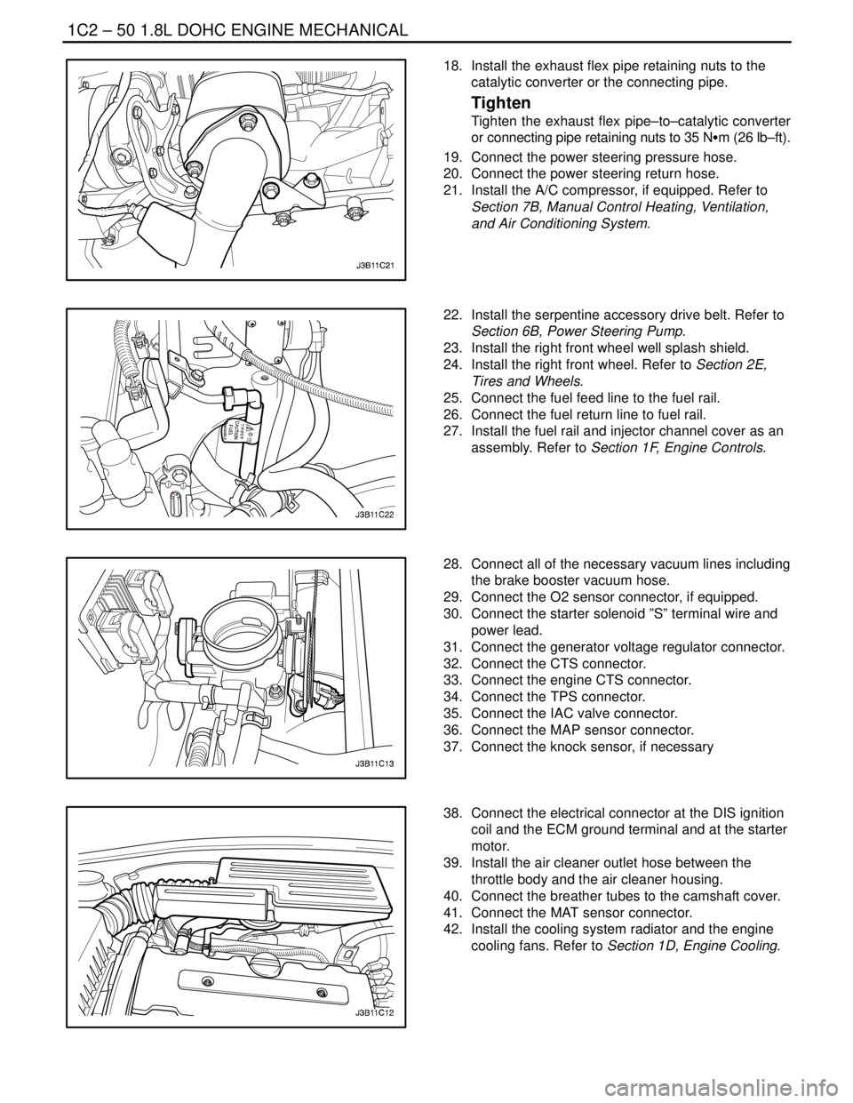
28. Connect all of the necessary vacuum lines including
the brake booster vacuum hose.
29. Connect the O2 sensor connector, if equipped.
30. Connect the starter solenoid ”S” terminal wire and
power lead.
31. Connect the generator voltage regulator connector.
32. Connect the CTS connector.
33. Connect the engine CTS connector.
34. Connect the TPS connector.
35. Connect the IAC valve connector.
36. Connect the MAP sensor connector.
37. Connect the knock sensor, if necessary
38. Connect the electrical connector at the DIS ignition
coil and the ECM ground terminal and at the starter
motor.
39. Install the air cleaner outlet hose between the
throttle body and the air cleaner housing.
40. Connect the breather tubes to the camshaft cover.
41. Connect the MAT sensor connector.
42. Install the cooling system radiator and the engine
cooling fans. Refer to Section 1D, Engine Cooling.
Page 195 of 2643

1.8L DOHC ENGINE MECHANICAL 1C2 – 75
DAEWOO V–121 BL4
GENERAL DESCRIPTION
AND SYSTEM OPERATION
CYLINDER HEAD AND GASKET
The cylinder head is made of an aluminum alloy. The cylin-
der head uses cross–flow intake and exhaust ports. A
spark plug is located in the center of each combustion
chamber. The cylinder head houses the dual camshafts.
CRANKSHAFT
The crankshaft has eight integral weights which are cast
with it for balancing. Oil holes run through the center of the
crankshaft to supply oil to the connecting rods, the bear-
ings, the pistons, and the other components. The end
thrust load is taken by the thrust washers installed at the
center journal.
TIMING BELT
The timing belt coordinates the crankshaft and the dual
overhead camshafts and keeps them synchronized. The
timing belt also turns the coolant pump. The timing belt
and the pulleys are toothed so that there is no slippage be-
tween them. There are two idler pulleys. An automatic ten-
sioner pulley maintains the timing belt’s correct tension.
The timing belt is made of a tough reinforced rubber similar
to that used on the serpentine drive belt. The timing belt
requires no lubrication.
OIL PUMP
The oil pump draws engine oil from the oil pan and feeds
it under pressure to the various parts of the engine. An oil
strainer is mounted before the inlet of the oil pump to re-
move impurities which could clog or damage the oil pump
or other engine components. When the crankshaft ro-
tates, the oil pump driven gear rotates. This causes the
space between the gears to constantly open and narrow,
pulling oil in from the oil pan when the space opens and
pumping the oil out to the engine as it narrows.
At high engine speeds, the oil pump supplies a much high-
er amount of oil than required for lubrication of the engine.
The oil pressure regulator prevents too much oil from en-
tering the engine lubrication passages. During normal oil
supply, a coil spring and valve keep the bypass closed, di-
recting all of the oil pumped to the engine. When the
amount of oil being pumped increases, the pressure be-
comes high enough to overcome the force of the spring.This opens the valve of the oil pressure regulator, allowing
the excess oil to flow through the valve and drain back to
the oil pan.
OIL PAN
The engine oil pan is mounted to the bottom of the cylinder
block. The engine oil pan houses the crankcase and is
made of cast aluminum.
Engine oil is pumped from the oil pan by the oil pump. After
it passes through the oil filter, it is fed through two paths
to lubricate the cylinder block and cylinder head. In one
path, the oil is pumped through oil passages in the crank-
shaft to the connecting rods, then to the pistons and cylin-
ders. It then drains back to the oil pan. In the second path,
the oil is pumped through passages to the camshaft. The
oil passes through the internal passageways in the cam-
shafts to lubricate the valve assemblies before draining
back to the oil pan.
EXHAUST MANIFOLD
A single four–port, rear–takedown manifold is used with
this engine. The manifold is designed to direct escaping
exhaust gases out of the combustion chambers with a
minimum of back pressure. The oxygen sensor is
mounted to the exhaust manifold.
INTAKE MANIFOLD
The intake manifold has four independent long ports and
utilizes an inertial supercharging effect to improve engine
torque at low and moderate speeds.
CAMSHAFTS
This engine is a dual overhead camshaft (DOHC) type,
which means there are two camshafts. One camshaft op-
erates the intake valves, and the other camshaft operates
the exhaust valves. The camshafts sit in journals on the
top of the engine (in the cylinder head) and are held in
place by camshaft caps. The camshaft journals of the cyl-
inder head are drilled for oil passages. Engine oil travels
to the camshafts under pressure where it lubricates each
camshaft journal. The oil returns to the oil pan through
drain holes in the cylinder head. The camshaft lobes are
machined into the solid camshaft to precisely open and
close the intake and the exhaust valves the correct
amount at the correct time. The camshaft lobes are oiled
by splash action from pressurized oil escaping from the
camshaft journals.
Page 198 of 2643
ENGINE COOLING 1D – 3
DAEWOO V–121 BL4
DIAGNOSIS
THERMOSTAT TEST
1. Remove the thermostat from the vehicle. Refer to
”Thermostat” in this section.
2. Make sure the valve spring is tight when the ther-
mostat is fully closed. If the spring is not tight, re-
place the thermostat.
3. Suspend the thermostat and a thermometer in a
pan of 50/50 mixture of ethylene glycol and water.
Do not let the thermostat or the thermometer rest
on the bottom of the pan because the uneven con-
centration of heat on the bottom could result in in-
accurate temperature measurements.
4. Heat the pan on a burner.
5. Use the thermometer to measure the temperature
of the heated solution.
6. The thermostat should begin to open at 87°C
(189°F) and it should be fully open at 102°C
(216°F). If it does not open at these temperatures,
replace the thermostat.
SURGE TANK CAP TEST
Tools Required
KM–471 Adapter
The surge tank cap maintains proper pressure, protects
the system from high pressure by opening a pressure
valve, and protects the coolant hoses from collapsing be-
cause of a vacuum.1. Wash any sludge from the surge tank cap and the
valve seat of the vacuum pressure valve for the
surge tank cap.
2. Check for any damage or deformity to the vacuum
pressure valve for the surge tank cap. If any dam-
age or deformity is found, replace the cap.
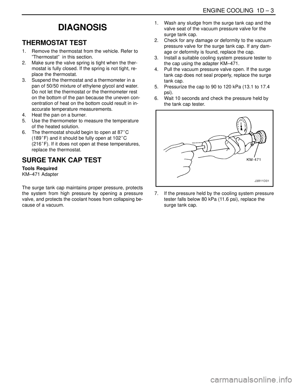
3. Install a suitable cooling system pressure tester to
the cap using the adapter KM–471.
4. Pull the vacuum pressure valve open. If the surge
tank cap does not seal properly, replace the surge
tank cap.
5. Pressurize the cap to 90 to 120 kPa (13.1 to 17.4
psi).
6. Wait 10 seconds and check the pressure held by
the tank cap tester.
7. If the pressure held by the cooling system pressure
tester falls below 80 kPa (11.6 psi), replace the
surge tank cap.
Page 204 of 2643
ENGINE COOLING 1D – 9
DAEWOO V–121 BL4
THERMOSTAT (1.4L/1.6L DOHC)
Removal Procedure
CAUTION : To prevent personal injury, do not remove
the surge tank cap while the engine and the radiator
are hot because the heat causes the system to remain
under pressure. Scalding fluid and steam may be
blown out under pressure.
1. Drain the coolant. Refer to ”Draining and Refilling
the Cooling System” in this section.
2. Loosen the hose clamp on the upper radiator hose
at the thermostat housing.
3. Disconnect the upper radiator hose from the ther-
mostat housing.
4. Loosen the clamp on the bypass hose.
5. Disconnect the bypass hose from the thermostat
housing.
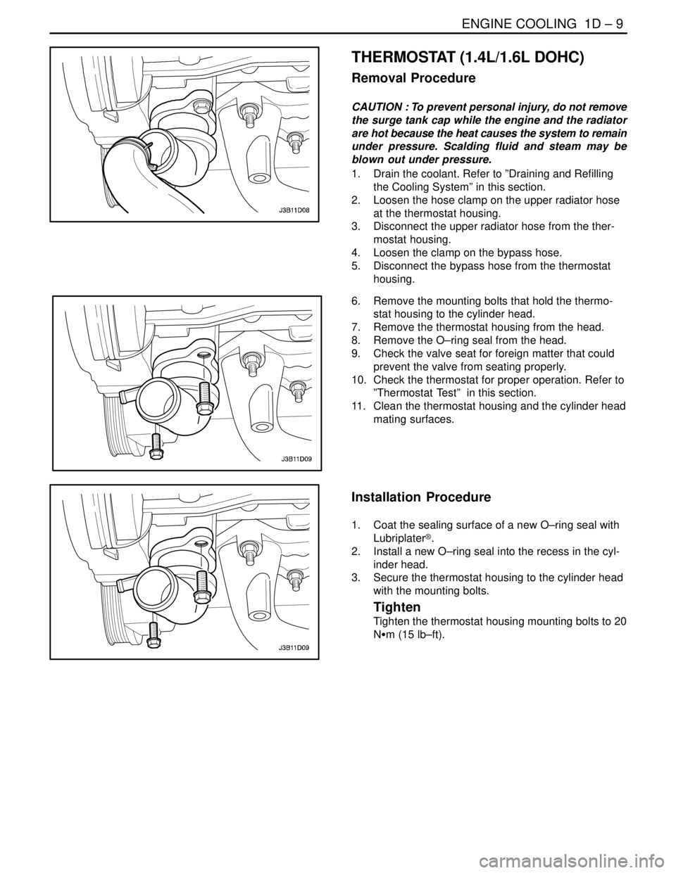
6. Remove the mounting bolts that hold the thermo-
stat housing to the cylinder head.
7. Remove the thermostat housing from the head.
8. Remove the O–ring seal from the head.
9. Check the valve seat for foreign matter that could
prevent the valve from seating properly.
10. Check the thermostat for proper operation. Refer to
”Thermostat Test” in this section.
11. Clean the thermostat housing and the cylinder head
mating surfaces.
Installation Procedure
1. Coat the sealing surface of a new O–ring seal with
Lubriplater®.
2. Install a new O–ring seal into the recess in the cyl-
inder head.
3. Secure the thermostat housing to the cylinder head
with the mounting bolts.
Tighten
Tighten the thermostat housing mounting bolts to 20
NSm (15 lb–ft).
Page 205 of 2643
1D – 10IENGINE COOLING
DAEWOO V–121 BL4
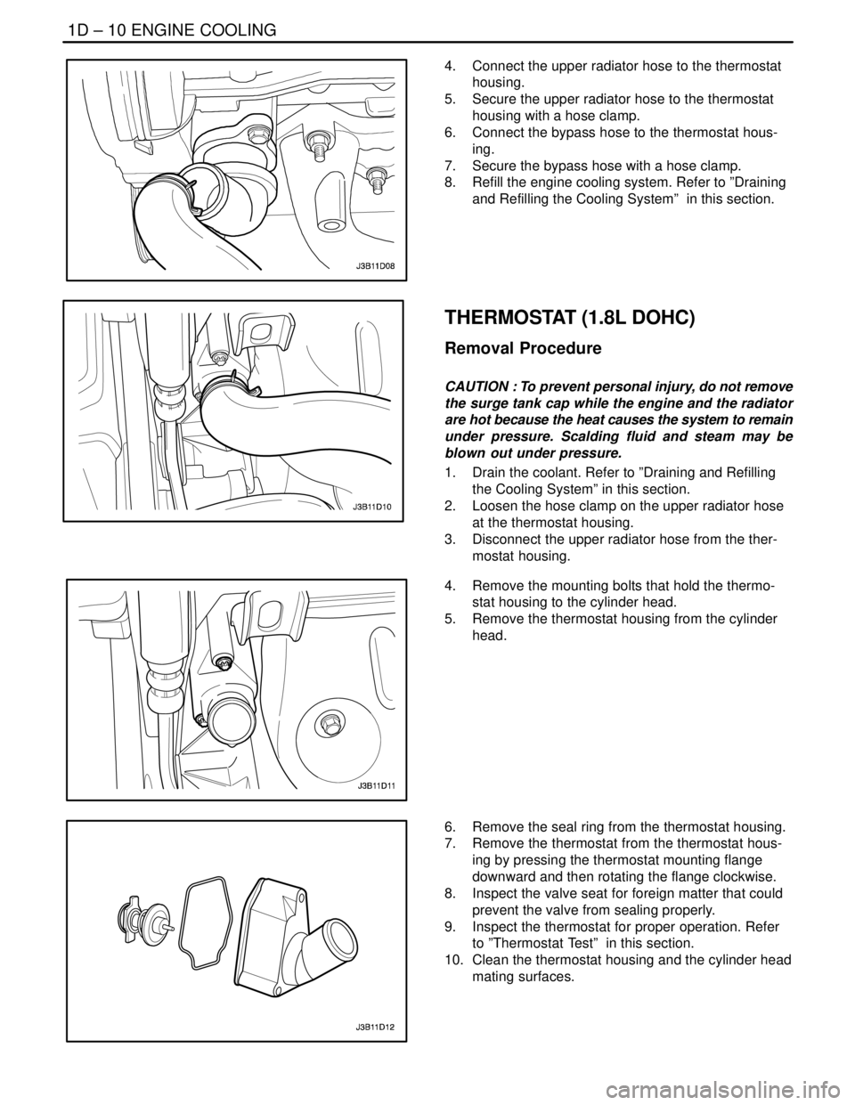
4. Connect the upper radiator hose to the thermostat
housing.
5. Secure the upper radiator hose to the thermostat
housing with a hose clamp.
6. Connect the bypass hose to the thermostat hous-
ing.
7. Secure the bypass hose with a hose clamp.
8. Refill the engine cooling system. Refer to ”Draining
and Refilling the Cooling System” in this section.
THERMOSTAT (1.8L DOHC)
Removal Procedure
CAUTION : To prevent personal injury, do not remove
the surge tank cap while the engine and the radiator
are hot because the heat causes the system to remain
under pressure. Scalding fluid and steam may be
blown out under pressure.
1. Drain the coolant. Refer to ”Draining and Refilling
the Cooling System” in this section.
2. Loosen the hose clamp on the upper radiator hose
at the thermostat housing.
3. Disconnect the upper radiator hose from the ther-
mostat housing.
4. Remove the mounting bolts that hold the thermo-
stat housing to the cylinder head.
5. Remove the thermostat housing from the cylinder
head.
6. Remove the seal ring from the thermostat housing.
7. Remove the thermostat from the thermostat hous-
ing by pressing the thermostat mounting flange
downward and then rotating the flange clockwise.
8. Inspect the valve seat for foreign matter that could
prevent the valve from sealing properly.
9. Inspect the thermostat for proper operation. Refer
to ”Thermostat Test” in this section.
10. Clean the thermostat housing and the cylinder head
mating surfaces.
Page 213 of 2643

1D – 18IENGINE COOLING
DAEWOO V–121 BL4
GENERAL DESCRIPTION
AND SYSTEM OPERATION
GENERAL DESCRIPTION
The cooling system maintains the engine temperature at
an efficient level during all engine operating conditions.
When the engine is cold, the cooling system cools the en-
gine slowly or not at all. This slow cooling of the engine al-
lows the engine to warm up quickly.
The cooling system includes a radiator and recovery sub-
system, cooling fans, a thermostat and housing, a coolant
pump, and a coolant pump drive belt. The timing belt
drives the coolant pump.
All components must function properly in order for the
cooling system to operate. The coolant pump draws the
coolant from the radiator. The coolant then circulates
through water jackets in the engine block, the intake man-
ifold, and the cylinder head. When the coolant reaches the
operating temperature of the thermostat, the thermostat
opens. The coolant then goes back to the radiator where
it cools.
This system directs some coolant through the hoses to the
heater core. This provides for heating and defrosting. The
surge tank is connected to the radiator to recover the cool-
ant displaced by expansion from the high temperatures.
The surge tank maintains the correct coolant level.
The cooling system for this vehicle has no radiator cap or
filler neck. The coolant is added to the cooling system
through the surge tank.
RADIATOR
This vehicle has a lightweight tube–and–fin aluminum ra-
diator. Plastic tanks are mounted on the right and the left
sides of the radiator core.
On vehicles equipped with automatic transaxles, the
transaxle fluid cooler lines run through the left radiator
tank. A radiator drain cock is on this radiator.
To drain the cooling system, open the drain cock.
SURGE TANK
The surge tank is a transparent plastic reservoir, similar to
the windshield washer reservoir.
The surge tank is connected to the radiator by a hose and
to the engine cooling system by another hose. As the ve-
hicle is driven, the engine coolant heats and expands. The
portion of the engine coolant displaced by this expansion
flows from the radiator and the engine into the surge tank.
The air trapped in the radiator and the engine is degassed
into the surge tank.When the engine stops, the engine coolant cools and con-
tracts. The displaced engine coolant is then drawn back
into the radiator and the engine. This keeps the radiator
filled with the coolant to the desired level at all times and
increases the cooling efficiency.
Maintain the coolant level between the MIN and the MAX
marks on the surge tank when the system is cold.
WATER PUMP
The belt–driven centrifugal water pump consists of an im-
peller, a drive shaft, and a belt pulley. The water pump is
mounted on the front of the transverse–mounted engine,
and is driven by the timing belt.
The impeller is supported by a completely sealed bearing.
The water pump is serviced as an assembly and, there-
fore, cannot be disassembled.
THERMOSTAT
A wax pellet–type thermostat controls the flow of the en-
gine coolant through the engine cooling system. The ther-
mostat is mounted in the thermostat housing to the front
of the cylinder head.
The thermostat stops the flow of the engine coolant from
the engine to the radiator in order to provide faster warm–
up, and to regulate the coolant temperature. The thermo-
stat remains closed while the engine coolant is cold, pre-
venting circulation of the engine coolant through the
radiator. At this point, the engine coolant is allowed to cir-
culate only throughout the heater core to warm it quickly
and evenly.
As the engine warms, the thermostat opens. This allows
the engine coolant to flow through the radiator, where the
heat is dissipated through the radiator. This opening and
closing of the thermostat permits enough engine coolant
to enter the radiator to keep the engine within proper en-
gine temperature operating limits.
The wax pellet in the thermostat is hermetically sealed in
a metal case. The wax element of the thermostat expands
when it is heated and contracts when it is cooled.
As the vehicle is driven and the engine warms, the engine
coolant temperature increases. When the engine coolant
reaches a specified temperature, the wax pellet element
in the thermostat expands and exerts pressure against the
metal case, forcing the valve open. This allows the engine
coolant to flow through the engine cooling system and cool
the engine.
As the wax pellet cools, the contraction allows a spring to
close the valve.
The thermostat begins to open at 87°C (189°F) and is fully
open at 102°C (216°F). The thermostat closes at 86°C
(187°F).