2004 CHRYSLER VOYAGER engine
[x] Cancel search: enginePage 2524 of 2585
OPERATION
OPERATION - SYSTEM
The Powertrain Control Module (PCM) monitors
many different circuits in the fuel injection, ignition,
emission and engine systems. If the PCM senses a
problem with a monitored circuit often enough to
indicate an actual problem, it stores a Diagnostic
Trouble Code (DTC) in the PCM's memory. If the
code applies to a non-emissions related component or
system, and the problem is repaired or ceases to
exist, the PCM cancels the code after 40 warmup
cycles. Diagnostic trouble codes that affect vehicle
emissions illuminate the Malfunction Indicator Lamp
(MIL). Refer to Malfunction Indicator Lamp in this
section.
Certain criteria must be met before the PCM
stores a DTC in memory. The criteria may be a spe-
cific range of engine RPM, engine temperature,
and/or input voltage to the PCM.
The PCM might not store a DTC for a monitored
circuit even though a malfunction has occurred. This
may happen because one of the DTC criteria for the
circuit has not been met.For example, assume the
diagnostic trouble code criteria requires the PCM to
monitor the circuit only when the engine operates
between 750 and 2000 RPM. Suppose the sensor's
output circuit shorts to ground when engine operates
above 2400 RPM (resulting in 0 volt input to the
PCM). Because the condition happens at an engine
speed above the maximum threshold (2000 rpm), the
PCM will not store a DTC.
There are several operating conditions for which
the PCM monitors and sets DTC's. Refer to Moni-
tored Systems, Components, and Non-Monitored Cir-
cuits in this section.
NOTE: Various diagnostic procedures may actually
cause a diagnostic monitor to set a DTC. For
instance, pulling a spark plug wire to perform a
spark test may set the misfire code. When a repair
is completed and verified, use the DRBIIITscan tool
to erase all DTC's and extinguish the MIL.Technicians can display stored DTC's. Refer to
Diagnostic Trouble Codes (Refer to 8 - ELECTRICAL/
ELECTRONIC CONTROL MODULES/POWER-
TRAIN CONTROL MODULE - DESCRIPTION). For
obtaining the DTC information, use the Data Link
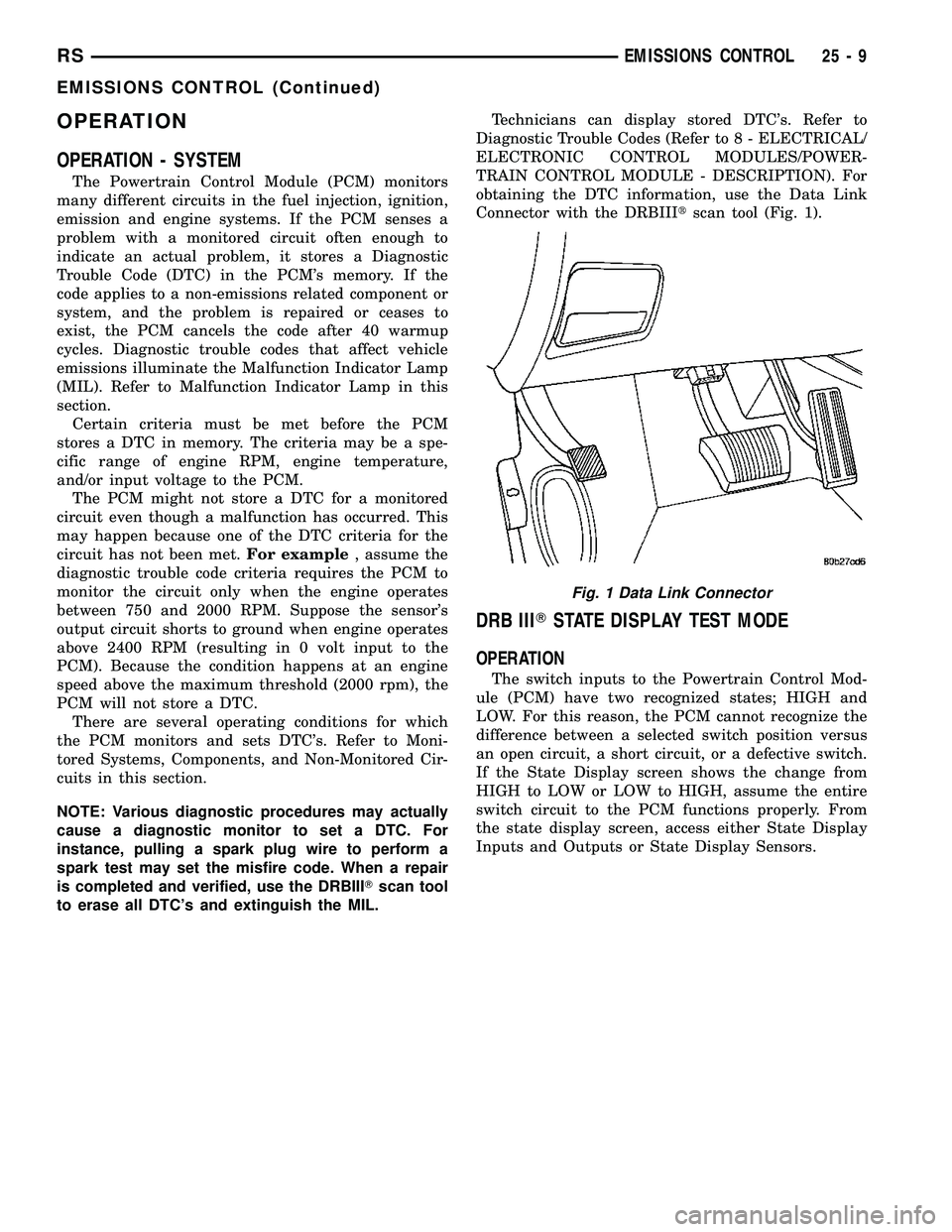
Connector with the DRBIIItscan tool (Fig. 1).
DRB IIITSTATE DISPLAY TEST MODE
OPERATION
The switch inputs to the Powertrain Control Mod-
ule (PCM) have two recognized states; HIGH and
LOW. For this reason, the PCM cannot recognize the
difference between a selected switch position versus
an open circuit, a short circuit, or a defective switch.
If the State Display screen shows the change from
HIGH to LOW or LOW to HIGH, assume the entire
switch circuit to the PCM functions properly. From
the state display screen, access either State Display
Inputs and Outputs or State Display Sensors.
Fig. 1 Data Link Connector
RSEMISSIONS CONTROL25-9
EMISSIONS CONTROL (Continued)
Page 2525 of 2585
EVAPORATIVE EMISSIONS
TABLE OF CONTENTS
page page
EVAPORATIVE EMISSIONS
OPERATION - EVAPORATION CONTROL
SYSTEM............................10
SPECIFICATIONS
TORQUE............................11
EVAP/PURGE SOLENOID
DESCRIPTION.........................12
OPERATION...........................12
REMOVAL.............................12
INSTALLATION.........................12
FUEL FILLER CAP
DESCRIPTION.........................12
OPERATION...........................12
NATURAL VAC LEAK DETECTION ASSY
REMOVAL.............................13
INSTALLATION.........................13
LEAK DETECTION PUMP
REMOVAL.............................13
INSTALLATION.........................13ORVR
OPERATION...........................14
DIAGNOSIS AND TESTING - VEHICLE DOES
NOT FILL............................16
P C V VA LV E
DESCRIPTION.........................16
OPERATION...........................16
DIAGNOSIS AND TESTING - PCV SYSTEM . . . 17
VAPOR CANISTER
DESCRIPTION.........................18
OPERATION...........................18
REMOVAL
REMOVAL...........................18
REMOVAL - WITH NVLD................19
REMOVAL - REAR EVAP CANISTER.......19
INSTALLATION
INSTALLATION.......................19
INSTALLATION - WITH NVLD............20
INSTALLATION - REAR EVAP CANISTER . . . 20
EVAPORATIVE EMISSIONS
OPERATION - EVAPORATION CONTROL
SYSTEM
The evaporation control system prevents the emis-
sion of fuel tank vapors into the atmosphere. When
fuel evaporates in the fuel tank, the vapors pass
through vent hoses or tubes to an activated carbon
filled evaporative canister. The canister temporarily
holds the vapors. The Powertrain Control Module
(PCM) allows intake manifold vacuum to draw
vapors into the combustion chambers during certain
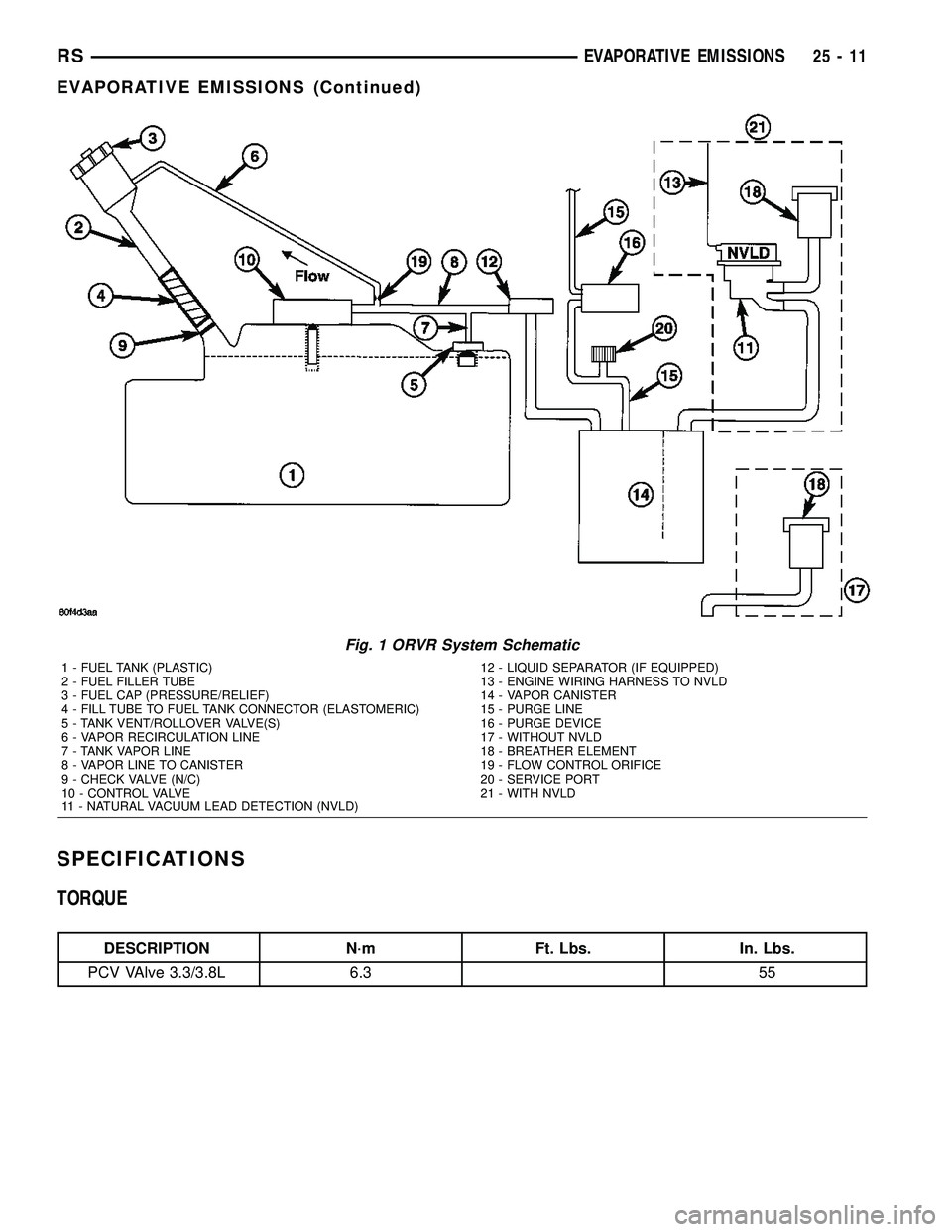
operating conditions (Fig. 1).All engines use a proportional purge solenoid sys-
tem. The PCM controls vapor flow by operating the
purge solenoid. Refer to Proportional Purge Solenoid
in this section.
NOTE: The evaporative system uses specially man-
ufactured hoses. If they need replacement, only use
fuel resistant hose. Also the hoses must be able to
pass an Ozone compliance test.
NOTE: For more information on Onboard Refueling
Vapor Recovery (ORVR), refer to the Fuel Delivery
section.
25 - 10 EVAPORATIVE EMISSIONSRS
Page 2526 of 2585
SPECIFICATIONS
TORQUE
DESCRIPTION N´m Ft. Lbs. In. Lbs.
PCV VAlve 3.3/3.8L 6.3 55
Fig. 1 ORVR System Schematic
1 - FUEL TANK (PLASTIC)
2 - FUEL FILLER TUBE
3 - FUEL CAP (PRESSURE/RELIEF)
4 - FILL TUBE TO FUEL TANK CONNECTOR (ELASTOMERIC)
5 - TANK VENT/ROLLOVER VALVE(S)
6 - VAPOR RECIRCULATION LINE
7 - TANK VAPOR LINE
8 - VAPOR LINE TO CANISTER
9 - CHECK VALVE (N/C)
10 - CONTROL VALVE
11 - NATURAL VACUUM LEAD DETECTION (NVLD)12 - LIQUID SEPARATOR (IF EQUIPPED)
13 - ENGINE WIRING HARNESS TO NVLD
14 - VAPOR CANISTER
15 - PURGE LINE
16 - PURGE DEVICE
17 - WITHOUT NVLD
18 - BREATHER ELEMENT
19 - FLOW CONTROL ORIFICE
20 - SERVICE PORT
21 - WITH NVLD
RSEVAPORATIVE EMISSIONS25-11
EVAPORATIVE EMISSIONS (Continued)
Page 2527 of 2585
EVAP/PURGE SOLENOID
DESCRIPTION
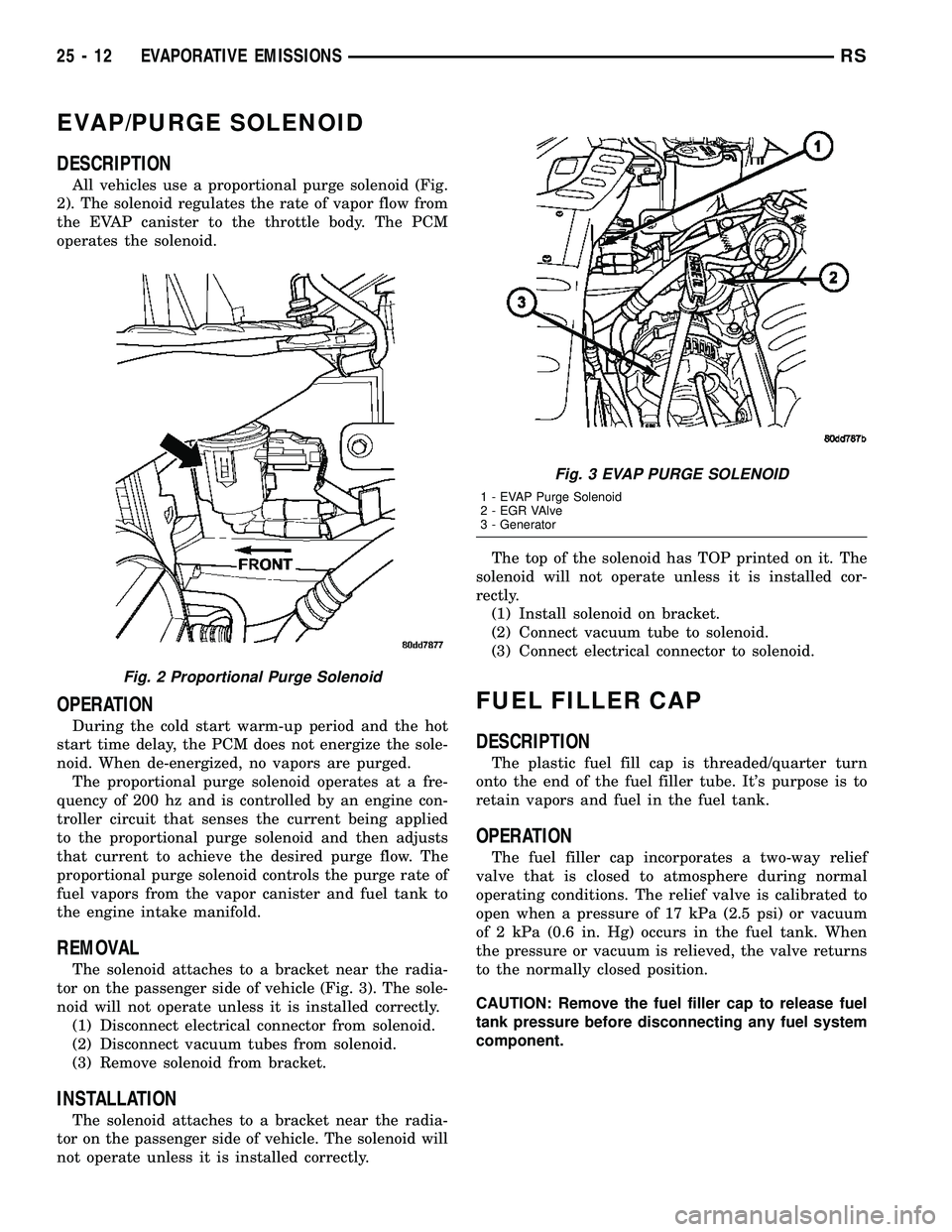
All vehicles use a proportional purge solenoid (Fig.
2). The solenoid regulates the rate of vapor flow from
the EVAP canister to the throttle body. The PCM
operates the solenoid.
OPERATION
During the cold start warm-up period and the hot
start time delay, the PCM does not energize the sole-
noid. When de-energized, no vapors are purged.
The proportional purge solenoid operates at a fre-
quency of 200 hz and is controlled by an engine con-
troller circuit that senses the current being applied
to the proportional purge solenoid and then adjusts
that current to achieve the desired purge flow. The
proportional purge solenoid controls the purge rate of
fuel vapors from the vapor canister and fuel tank to
the engine intake manifold.
REMOVAL
The solenoid attaches to a bracket near the radia-
tor on the passenger side of vehicle (Fig. 3). The sole-
noid will not operate unless it is installed correctly.
(1) Disconnect electrical connector from solenoid.
(2) Disconnect vacuum tubes from solenoid.
(3) Remove solenoid from bracket.
INSTALLATION
The solenoid attaches to a bracket near the radia-
tor on the passenger side of vehicle. The solenoid will
not operate unless it is installed correctly.The top of the solenoid has TOP printed on it. The
solenoid will not operate unless it is installed cor-
rectly.
(1) Install solenoid on bracket.
(2) Connect vacuum tube to solenoid.
(3) Connect electrical connector to solenoid.
FUEL FILLER CAP
DESCRIPTION
The plastic fuel fill cap is threaded/quarter turn
onto the end of the fuel filler tube. It's purpose is to
retain vapors and fuel in the fuel tank.
OPERATION
The fuel filler cap incorporates a two-way relief
valve that is closed to atmosphere during normal
operating conditions. The relief valve is calibrated to
open when a pressure of 17 kPa (2.5 psi) or vacuum
of 2 kPa (0.6 in. Hg) occurs in the fuel tank. When
the pressure or vacuum is relieved, the valve returns
to the normally closed position.
CAUTION: Remove the fuel filler cap to release fuel
tank pressure before disconnecting any fuel system
component.
Fig. 2 Proportional Purge Solenoid
Fig. 3 EVAP PURGE SOLENOID
1 - EVAP Purge Solenoid
2 - EGR VAlve
3 - Generator
25 - 12 EVAPORATIVE EMISSIONSRS
Page 2529 of 2585
ORVR
OPERATION
The emission control principle used in the ORVR
system is that the fuel flowing into the filler tube
(appx. 1º I.D.) creates an aspiration effect which
draws air into the fill tube (Fig. 9). During refueling,
the fuel tank is vented to the vapor canister to cap-
ture escaping vapors. With air flowing into the filler
tube, there are no fuel vapors escaping to the atmo-
sphere. Once the refueling vapors are captured by
the canister, the vehicle's computer controlled purge
system draws vapor out of the canister for the engine
to burn. The vapors flow is metered by the purge
solenoid so that there is no or minimal impact on
driveability or tailpipe emissions.
As fuel starts to flow through the fill tube, it opens
the normally closed check valve and enters the fuel
tank. Vapor or air is expelled from the tank through
the control valve to the vapor canister. Vapor is
absorbed in the canister until vapor flow in the lines
stops, either following shut-off or by having the fuel
level in the tank rise high enough to close the control
valve. The control valve(Refer to 14 - FUEL SYS-
TEM/FUEL DELIVERY/FUEL TANK - OPERATION)
contains a float that rises to seal the large diameter
vent path to the canister. At this point in the fueling
of the vehicle, the tank pressure increases, the check
valve closes (preventing tank fuel from spitting back
at the operator), and fuel then rises up the filler tube
to shut-off the dispensing nozzle.
If the engine is shut-off while the On-Board diag-
nostics test is running, low level tank pressure can
be trapped in the fuel tank and fuel can not be added
to the tank until the pressure is relieved. This is due
to the leak detection pump closing the vapor outlet
from the top of the tank and the one-way check valve
not allowing the tank to vent through the fill tube to
atmosphere. Therefore, when fuel is added, it will
back-up in the fill tube and shut off the dispensing
nozzle. The pressure can be eliminated in two ways:
1. Vehicle purge must be activated and for a long
enough period to eliminate the pressure. 2. Removing
the fuel cap and allowing enough time for the system
to vent thru the recirulation tube.
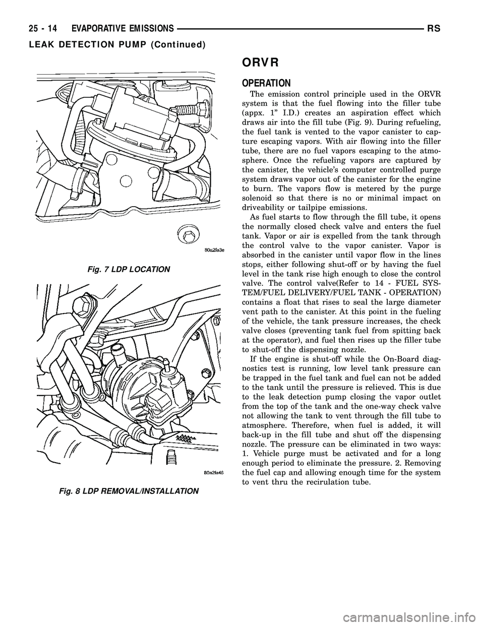
Fig. 7 LDP LOCATION
Fig. 8 LDP REMOVAL/INSTALLATION
25 - 14 EVAPORATIVE EMISSIONSRS
LEAK DETECTION PUMP (Continued)
Page 2530 of 2585

Fig. 9 ORVR System Schematic
1 - FUEL TANK (PLASTIC)
2 - FUEL FILLER TUBE
3 - FUEL CAP (PRESSURE/RELIEF)
4 - FILL TUBE TO FUEL TANK CONNECTOR (ELASTOMERIC)
5 - TANK VENT/ROLLOVER VALVE(S)
6 - VAPOR RECIRCULATION LINE
7 - TANK VAPOR LINE
8 - VAPOR LINE TO CANISTER
9 - CHECK VALVE (N/C)
10 - CONTROL VALVE
11 - NATURAL VACUUM LEAD DETECTION (NVLD)12 - LIQUID SEPARATOR (IF EQUIPPED)
13 - ENGINE WIRING HARNESS TO NVLD
14 - VAPOR CANISTER
15 - PURGE LINE
16 - PURGE DEVICE
17 - WITHOUT NVLD
18 - BREATHER ELEMENT
19 - FLOW CONTROL ORIFICE
20 - SERVICE PORT
21 - WITH NVLD
RSEVAPORATIVE EMISSIONS25-15
ORVR (Continued)
Page 2531 of 2585
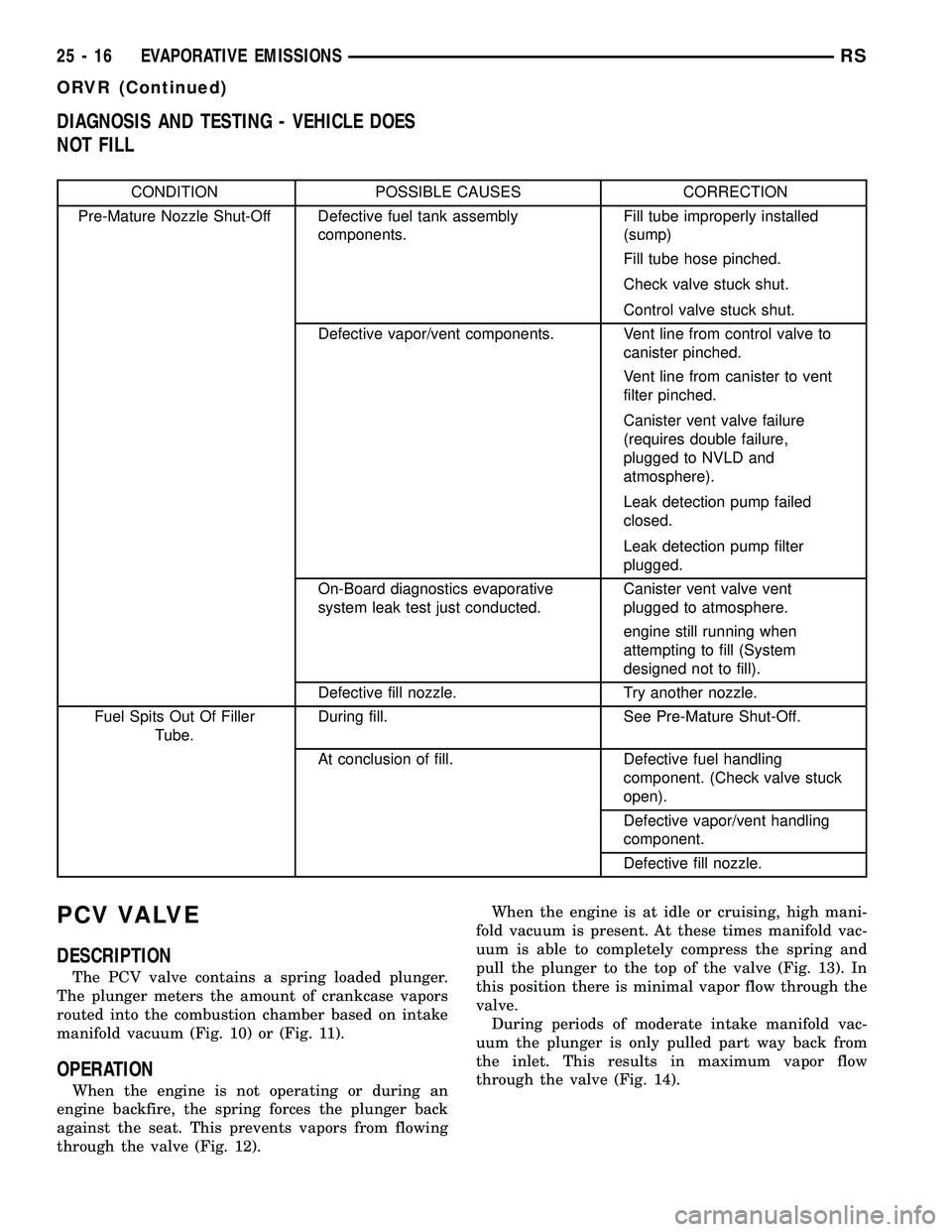
DIAGNOSIS AND TESTING - VEHICLE DOES
NOT FILL
CONDITION POSSIBLE CAUSES CORRECTION
Pre-Mature Nozzle Shut-Off Defective fuel tank assembly
components.Fill tube improperly installed
(sump)
Fill tube hose pinched.
Check valve stuck shut.
Control valve stuck shut.
Defective vapor/vent components. Vent line from control valve to
canister pinched.
Vent line from canister to vent
filter pinched.
Canister vent valve failure
(requires double failure,
plugged to NVLD and
atmosphere).
Leak detection pump failed
closed.
Leak detection pump filter
plugged.
On-Board diagnostics evaporative
system leak test just conducted.Canister vent valve vent
plugged to atmosphere.
engine still running when
attempting to fill (System
designed not to fill).
Defective fill nozzle. Try another nozzle.
Fuel Spits Out Of Filler
Tube.During fill. See Pre-Mature Shut-Off.
At conclusion of fill. Defective fuel handling
component. (Check valve stuck
open).
Defective vapor/vent handling
component.
Defective fill nozzle.
PCV VALVE
DESCRIPTION
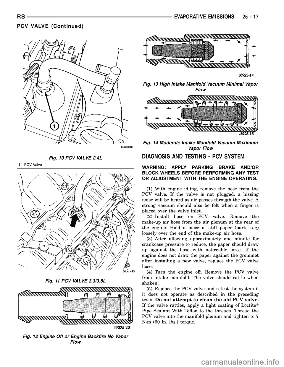
The PCV valve contains a spring loaded plunger.
The plunger meters the amount of crankcase vapors
routed into the combustion chamber based on intake
manifold vacuum (Fig. 10) or (Fig. 11).
OPERATION
When the engine is not operating or during an
engine backfire, the spring forces the plunger back
against the seat. This prevents vapors from flowing
through the valve (Fig. 12).When the engine is at idle or cruising, high mani-
fold vacuum is present. At these times manifold vac-
uum is able to completely compress the spring and
pull the plunger to the top of the valve (Fig. 13). In
this position there is minimal vapor flow through the
valve.
During periods of moderate intake manifold vac-
uum the plunger is only pulled part way back from
the inlet. This results in maximum vapor flow
through the valve (Fig. 14).
25 - 16 EVAPORATIVE EMISSIONSRS
ORVR (Continued)
Page 2532 of 2585
DIAGNOSIS AND TESTING - PCV SYSTEM
WARNING: APPLY PARKING BRAKE AND/OR
BLOCK WHEELS BEFORE PERFORMING ANY TEST
OR ADJUSTMENT WITH THE ENGINE OPERATING.
(1) With engine idling, remove the hose from the
PCV valve. If the valve is not plugged, a hissing
noise will be heard as air passes through the valve. A
strong vacuum should also be felt when a finger is
placed over the valve inlet.
(2) Install hose on PCV valve. Remove the
make-up air hose from the air plenum at the rear of
the engine. Hold a piece of stiff paper (parts tag)
loosely over the end of the make-up air hose.
(3) After allowing approximately one minute for
crankcase pressure to reduce, the paper should draw
up against the hose with noticeable force. If the
engine does not draw the paper against the grommet
after installing a new valve, replace the PCV valve
hose.
(4) Turn the engine off. Remove the PCV valve
from intake manifold. The valve should rattle when
shaken.
(5) Replace the PCV valve and retest the system if
it does not operate as described in the preceding
tests.Do not attempt to clean the old PCV valve.
If the valve rattles, apply a light coating of Loctitet
Pipe Sealant With Teflon to the threads. Thread the
PCV valve into the manifold plenum and tighten to 7
N´m (60 in. lbs.) torque.
Fig. 10 PCV VALVE 2.4L
1 - PCV Valve
Fig. 11 PCV VALVE 3.3/3.8L
Fig. 12 Engine Off or Engine Backfire No Vapor
Flow
Fig. 13 High Intake Manifold Vacuum Minimal Vapor
Flow
Fig. 14 Moderate Intake Manifold Vacuum Maximum
Vapor Flow
RSEVAPORATIVE EMISSIONS25-17
PCV VALVE (Continued)