2004 CHRYSLER VOYAGER oil type
[x] Cancel search: oil typePage 1478 of 2585
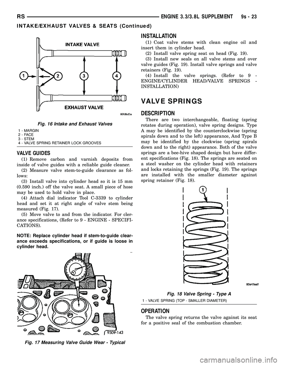
VALVE GUIDES
(1) Remove carbon and varnish deposits from
inside of valve guides with a reliable guide cleaner.
(2) Measure valve stem-to-guide clearance as fol-
lows:
(3) Install valve into cylinder head so it is 15 mm
(0.590 inch.) off the valve seat. A small piece of hose
may be used to hold valve in place.
(4) Attach dial indicator Tool C-3339 to cylinder
head and set it at right angle of valve stem being
measured (Fig. 17).
(5) Move valve to and from the indicator. For cler-
ance specifications, (Refer to 9 - ENGINE - SPECIFI-
CATIONS).
NOTE: Replace cylinder head if stem-to-guide clear-
ance exceeds specifications, or if guide is loose in
cylinder head.
INSTALLATION
(1) Coat valve stems with clean engine oil and
insert them in cylinder head.
(2) Install valve spring seat on head (Fig. 19).
(3) Install new seals on all valve stems and over
valve guides (Fig. 19). Install valve springs and valve
retainers (Fig. 19).
(4) Install the valve springs. (Refer to 9 -
ENGINE/CYLINDER HEAD/VALVE SPRINGS -
INSTALLATION)
VALVE SPRINGS
DESCRIPTION
There are two interchangeable, floating (spring
rotates during operation), valve spring designs. Type
A may be identified by the counterclockwise (spring
spirals down and to the left) appearance, And Type B
may be identified by the clockwise (spring spirals
down and to the right) appearance. Both of the valve
springs are a bee-hive shaped design but have differ-
ent specifications (Fig. 18). The springs are seated on
a steel washer on the cylinder head with retainers
and locks retaining the springs (Fig. 19). The springs
are installed with the smaller diameter against
spring retainer (Fig. 18).
OPERATION
The valve spring returns the valve against its seat
for a positive seal of the combustion chamber.
Fig. 16 Intake and Exhaust Valves
1 - MARGIN
2-FACE
3 - STEM
4 - VALVE SPRING RETAINER LOCK GROOVES
Fig. 17 Measuring Valve Guide Wear - Typical
Fig. 18 Valve Spring - Type A
1 - VALVE SPRING (TOP - SMALLER DIAMETER)
RSENGINE 3.3/3.8L SUPPLEMENT9s-23
INTAKE/EXHAUST VALVES & SEATS (Continued)
Page 1492 of 2585
OPERATION
Heat shields are needed to protect both the vehicle
and the environment from the high temperatures
developed near the catalytic converter.
Avoid application of rust prevention com-
pounds or undercoating materials to exhaust
system floor pan heat shields on cars so
equipped. Light over spray near the edges is
permitted. Application of coating will greatly
reduce the efficiency of the heat shields result-
ing in excessive floor pan temperatures and
objectionable fumes.
REMOVAL
(1) Raise vehicle on hoist.
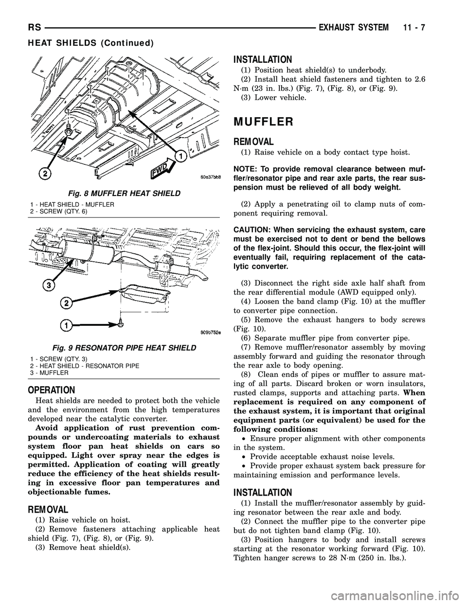
(2) Remove fasteners attaching applicable heat
shield (Fig. 7), (Fig. 8), or (Fig. 9).
(3) Remove heat shield(s).
INSTALLATION
(1) Position heat shield(s) to underbody.
(2) Install heat shield fasteners and tighten to 2.6
N´m (23 in. lbs.) (Fig. 7), (Fig. 8), or (Fig. 9).
(3) Lower vehicle.
MUFFLER
REMOVAL
(1) Raise vehicle on a body contact type hoist.
NOTE: To provide removal clearance between muf-
fler/resonator pipe and rear axle parts, the rear sus-
pension must be relieved of all body weight.
(2) Apply a penetrating oil to clamp nuts of com-
ponent requiring removal.
CAUTION: When servicing the exhaust system, care
must be exercised not to dent or bend the bellows
of the flex-joint. Should this occur, the flex-joint will
eventually fail, requiring replacement of the cata-
lytic converter.
(3) Disconnect the right side axle half shaft from
the rear differential module (AWD equipped only).
(4) Loosen the band clamp (Fig. 10) at the muffler
to converter pipe connection.
(5) Remove the exhaust hangers to body screws
(Fig. 10).
(6) Separate muffler pipe from converter pipe.
(7) Remove muffler/resonator assembly by moving
assembly forward and guiding the resonator through
the rear axle to body opening.
(8) Clean ends of pipes or muffler to assure mat-
ing of all parts. Discard broken or worn insulators,
rusted clamps, supports and attaching parts.When
replacement is required on any component of
the exhaust system, it is important that original
equipment parts (or equivalent) be used for the
following conditions:
²Ensure proper alignment with other components
in the system.
²Provide acceptable exhaust noise levels.
²Provide proper exhaust system back pressure for
maintaining emission and performance levels.
INSTALLATION
(1) Install the muffler/resonator assembly by guid-
ing resonator between the rear axle and body.
(2) Connect the muffler pipe to the converter pipe
but do not tighten band clamp (Fig. 10).
(3) Position hangers to body and install screws
starting at the resonator working forward (Fig. 10).
Tighten hanger screws to 28 N´m (250 in. lbs.).
Fig. 8 MUFFLER HEAT SHIELD
1 - HEAT SHIELD - MUFFLER
2 - SCREW (QTY. 6)
Fig. 9 RESONATOR PIPE HEAT SHIELD
1 - SCREW (QTY. 3)
2 - HEAT SHIELD - RESONATOR PIPE
3 - MUFFLER
RSEXHAUST SYSTEM11-7
HEAT SHIELDS (Continued)
Page 1504 of 2585
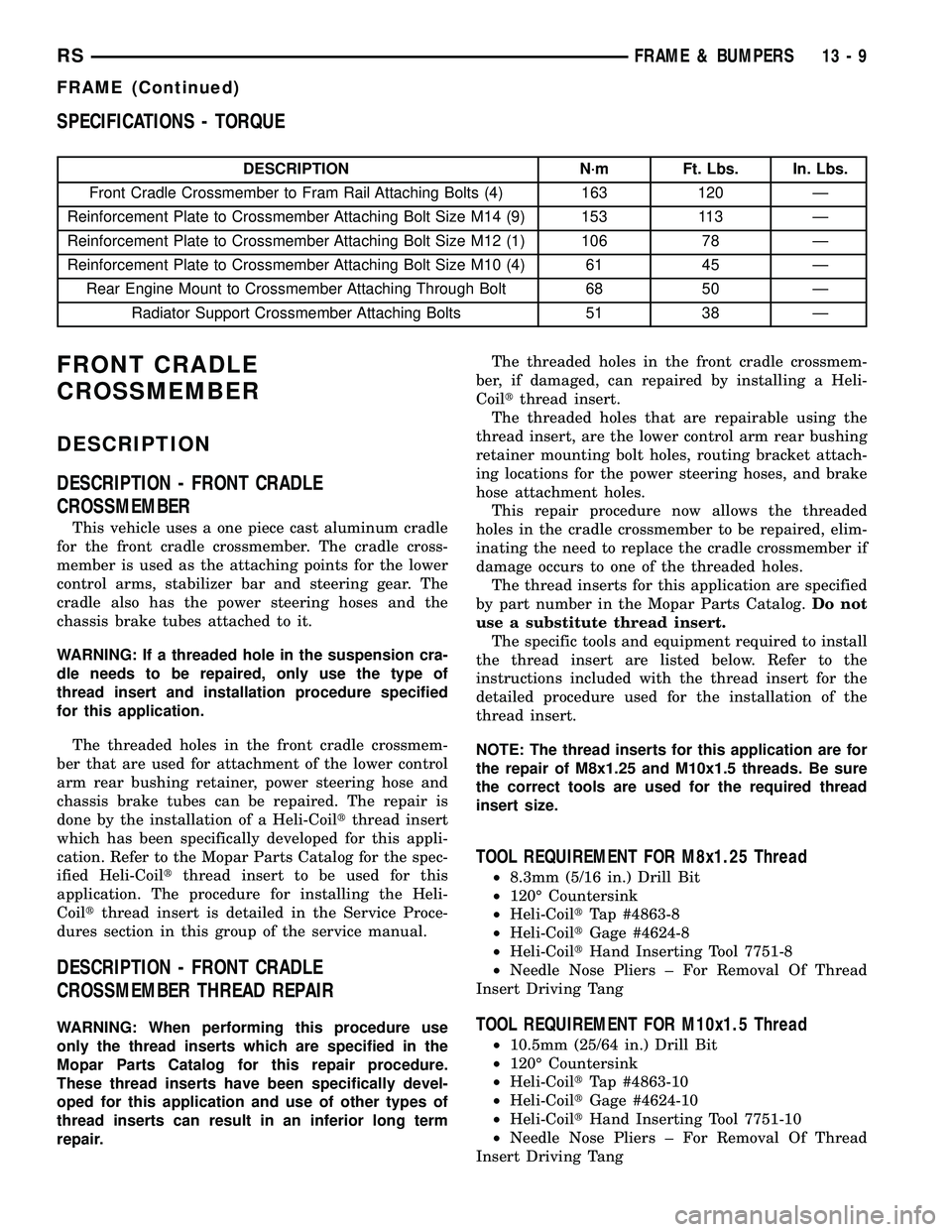
SPECIFICATIONS - TORQUE
DESCRIPTION N´m Ft. Lbs. In. Lbs.
Front Cradle Crossmember to Fram Rail Attaching Bolts (4) 163 120 Ð
Reinforcement Plate to Crossmember Attaching Bolt Size M14 (9) 153 113 Ð
Reinforcement Plate to Crossmember Attaching Bolt Size M12 (1) 106 78 Ð
Reinforcement Plate to Crossmember Attaching Bolt Size M10 (4) 61 45 Ð
Rear Engine Mount to Crossmember Attaching Through Bolt 68 50 Ð
Radiator Support Crossmember Attaching Bolts 51 38 Ð
FRONT CRADLE
CROSSMEMBER
DESCRIPTION
DESCRIPTION - FRONT CRADLE
CROSSMEMBER
This vehicle uses a one piece cast aluminum cradle
for the front cradle crossmember. The cradle cross-
member is used as the attaching points for the lower
control arms, stabilizer bar and steering gear. The
cradle also has the power steering hoses and the
chassis brake tubes attached to it.
WARNING: If a threaded hole in the suspension cra-
dle needs to be repaired, only use the type of
thread insert and installation procedure specified
for this application.
The threaded holes in the front cradle crossmem-
ber that are used for attachment of the lower control
arm rear bushing retainer, power steering hose and
chassis brake tubes can be repaired. The repair is
done by the installation of a Heli-Coiltthread insert
which has been specifically developed for this appli-
cation. Refer to the Mopar Parts Catalog for the spec-
ified Heli-Coiltthread insert to be used for this
application. The procedure for installing the Heli-
Coiltthread insert is detailed in the Service Proce-
dures section in this group of the service manual.
DESCRIPTION - FRONT CRADLE
CROSSMEMBER THREAD REPAIR
WARNING: When performing this procedure use
only the thread inserts which are specified in the
Mopar Parts Catalog for this repair procedure.
These thread inserts have been specifically devel-
oped for this application and use of other types of
thread inserts can result in an inferior long term
repair.The threaded holes in the front cradle crossmem-
ber, if damaged, can repaired by installing a Heli-
Coiltthread insert.
The threaded holes that are repairable using the
thread insert, are the lower control arm rear bushing
retainer mounting bolt holes, routing bracket attach-
ing locations for the power steering hoses, and brake
hose attachment holes.
This repair procedure now allows the threaded
holes in the cradle crossmember to be repaired, elim-
inating the need to replace the cradle crossmember if
damage occurs to one of the threaded holes.
The thread inserts for this application are specified
by part number in the Mopar Parts Catalog.Do not
use a substitute thread insert.
The specific tools and equipment required to install
the thread insert are listed below. Refer to the
instructions included with the thread insert for the
detailed procedure used for the installation of the
thread insert.
NOTE: The thread inserts for this application are for
the repair of M8x1.25 and M10x1.5 threads. Be sure
the correct tools are used for the required thread
insert size.
TOOL REQUIREMENT FOR M8x1.25 Thread
²8.3mm (5/16 in.) Drill Bit
²120É Countersink
²Heli-CoiltTap #4863-8
²Heli-CoiltGage #4624-8
²Heli-CoiltHand Inserting Tool 7751-8
²Needle Nose Pliers ± For Removal Of Thread
Insert Driving Tang
TOOL REQUIREMENT FOR M10x1.5 Thread
²10.5mm (25/64 in.) Drill Bit
²120É Countersink
²Heli-CoiltTap #4863-10
²Heli-CoiltGage #4624-10
²Heli-CoiltHand Inserting Tool 7751-10
²Needle Nose Pliers ± For Removal Of Thread
Insert Driving Tang
RSFRAME & BUMPERS13-9
FRAME (Continued)
Page 1514 of 2585
nated fuel in this system. If it is necessary to replace
these lines/tubes/hoses, use new original equipment
lines/tubes/hoses.
If equipped:The hose clamps used to secure rub-
ber hoses on vehicles are of a special rolled edge con-
struction. This construction is used to prevent the
edge of the clamp from cutting into the hose. Only
these rolled edge type clamps may be used in this
system. All other types of clamps may cut into the
hoses and cause leaks.
Use new original equipment type hose clamps.
STANDARD PROCEDURE - HOSES AND CLAMP
Inspect all hose connections (clamps and quick con-
nect fittings) for completeness and leaks. Replace
cracked, scuffed, or swelled hoses. Replace hoses that
rub against other vehicle components or show sign of
wear.
Fuel injected vehicles use specially constructed
hoses. When replacing hoses, only use hoses marked
EFM/EFI.
When installing hoses, ensure that they are routed
away from contact with other vehicle components
that could rub against them and cause failure. Avoid
contact with clamps or other components that cause
abrasions or scuffing. Ensure that rubber hoses are
properly routed and avoid heat sources.
The hose clamps have rolled edges to prevent the
clamp from cutting into the hose. Only use clamps
that are original equipment or equivalent. Other
types of clamps may cut into the hoses and cause
high pressure fuel leaks. Tighten hose clamps to 1
N´m (9 in. lbs.) torque.
Inspect all hose connections such as clamps, cou-
plings and fittings to make sure they are secure and
leaks are not present. The component should be
replaced immediately if there is any evidence of deg-
radation that could result in failure.
Never attempt to repair a plastic fuel line/tube.
Replace as necessary.
Avoid contact of any fuel tubes/hoses with other
vehicle components that could cause abrasions or
scuffing. Be sure that the plastic fuel lines/tubes are
properly routed to prevent pinching and to avoid heat
sources.
FUEL PRESSURE REGULATOR
OPERATION
The fuel system uses a nonadjustable pressure reg-
ulator that maintains fuel system pressure at
approximately 400 34 kPa (58 5 psi). The fuel
pressure regulator contains a diaphragm, calibrated
spring and a fuel return valve. The spring pushes
down on the diaphragm and closes off the fuel returnport. System fuel pressure reflects the amount of fuel
pressure required to open the return port.
The pressure regulator is a mechanical device that
is NOT controlled by the PCM or engine vacuum.
REMOVAL
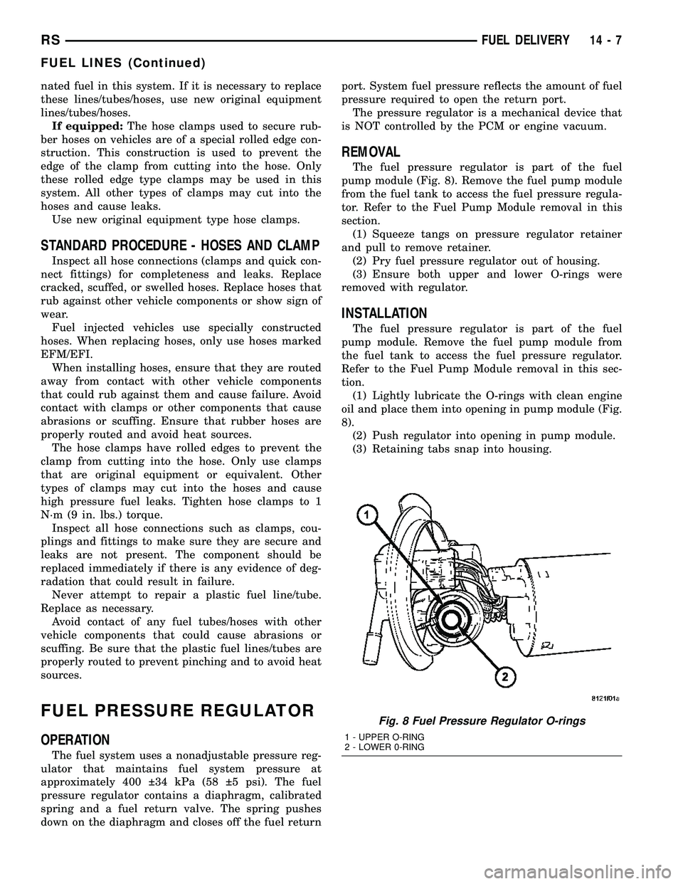
The fuel pressure regulator is part of the fuel
pump module (Fig. 8). Remove the fuel pump module
from the fuel tank to access the fuel pressure regula-
tor. Refer to the Fuel Pump Module removal in this
section.
(1) Squeeze tangs on pressure regulator retainer
and pull to remove retainer.
(2) Pry fuel pressure regulator out of housing.
(3) Ensure both upper and lower O-rings were
removed with regulator.
INSTALLATION
The fuel pressure regulator is part of the fuel
pump module. Remove the fuel pump module from
the fuel tank to access the fuel pressure regulator.
Refer to the Fuel Pump Module removal in this sec-
tion.
(1) Lightly lubricate the O-rings with clean engine
oil and place them into opening in pump module (Fig.
8).
(2) Push regulator into opening in pump module.
(3) Retaining tabs snap into housing.
Fig. 8 Fuel Pressure Regulator O-rings
1 - UPPER O-RING
2 - LOWER 0-RING
RSFUEL DELIVERY14-7
FUEL LINES (Continued)
Page 1521 of 2585
QUICK CONNECT FITTING
STANDARD PROCEDURE - QUICK-CONNECT
FITTINGS
REMOVAL
When disconnecting a quick-connect fitting, the
retainer will remain on the fuel tube nipple.
WARNING: RELEASE FUEL SYSTEM PRESSURE
BEFORE DISCONNECTING A QUICK-CONNECT FIT-
TINGS. REFER TO THE FUEL PRESSURE RELEASE
PROCEDURE. THIS MAY RESULT IN PERSONAL
INJURY OR DEATH.
(1) Perform Fuel Pressure Release Procedure.
Refer to the Fuel Pressure Release Procedure in this
section.
(2) Disconnect negative cable from battery or aux-
iliary jumper terminal.
(3) Squeeze retainer tabs together and pull fuel
tube/quick-connect fitting assembly off of fuel tube
nipple. The retainer will remain on fuel tube.
INSTALLATION
CAUTION: Make sure that the o-ring in installed in
fitting. Never install a quick-connect fitting without
the retainer being either on the fuel tube or already
in the quick-connect fitting. In either case, ensure
the retainer locks securely into the quick-connect
fitting by firmly push-pulling-push on fuel tube and
fitting to ensure it is secured.
(1) Using a clean lint free cloth, clean the fuel tube
nipple and retainer.
(2) Prior to connecting the fitting to the fuel tube,
coat the fuel tube nipple with clean engine oil.
(3) Push the quick-connect fitting over the fuel
tube until theretainer seats and a click is heard.
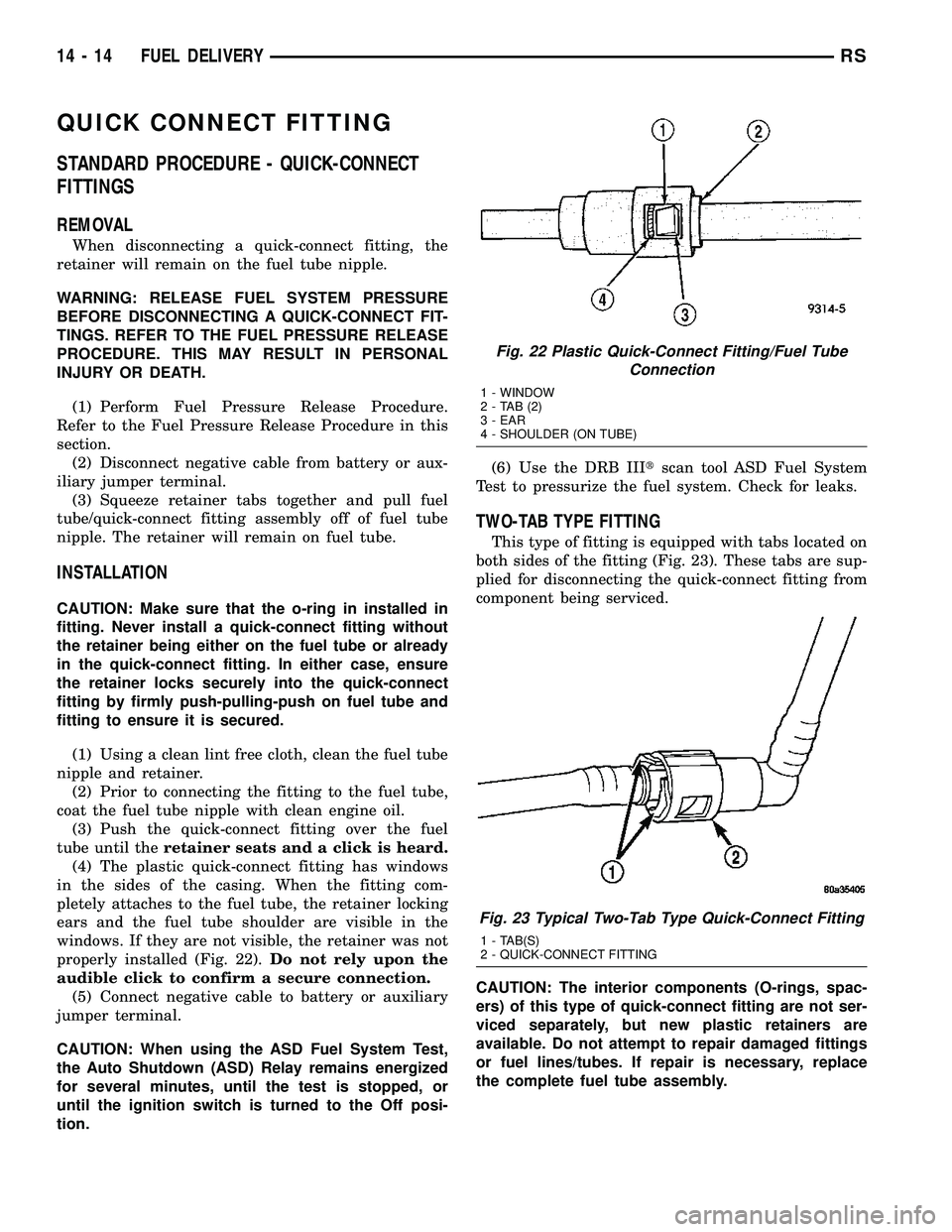
(4) The plastic quick-connect fitting has windows
in the sides of the casing. When the fitting com-
pletely attaches to the fuel tube, the retainer locking
ears and the fuel tube shoulder are visible in the
windows. If they are not visible, the retainer was not
properly installed (Fig. 22).Do not rely upon the
audible click to confirm a secure connection.
(5) Connect negative cable to battery or auxiliary
jumper terminal.
CAUTION: When using the ASD Fuel System Test,
the Auto Shutdown (ASD) Relay remains energized
for several minutes, until the test is stopped, or
until the ignition switch is turned to the Off posi-
tion.(6) Use the DRB IIItscan tool ASD Fuel System
Test to pressurize the fuel system. Check for leaks.
TWO-TAB TYPE FITTING
This type of fitting is equipped with tabs located on
both sides of the fitting (Fig. 23). These tabs are sup-
plied for disconnecting the quick-connect fitting from
component being serviced.
CAUTION: The interior components (O-rings, spac-
ers) of this type of quick-connect fitting are not ser-
viced separately, but new plastic retainers are
available. Do not attempt to repair damaged fittings
or fuel lines/tubes. If repair is necessary, replace
the complete fuel tube assembly.
Fig. 22 Plastic Quick-Connect Fitting/Fuel Tube
Connection
1 - WINDOW
2-TAB(2)
3 - EAR
4 - SHOULDER (ON TUBE)
Fig. 23 Typical Two-Tab Type Quick-Connect Fitting
1 - TAB(S)
2 - QUICK-CONNECT FITTING
14 - 14 FUEL DELIVERYRS
Page 1522 of 2585
WARNING: THE FUEL SYSTEM IS UNDER A CON-
STANT PRESSURE (EVEN WITH THE ENGINE OFF).
BEFORE SERVICING ANY FUEL SYSTEM HOSES,
FITTINGS OR LINES, THE FUEL SYSTEM PRES-
SURE MUST BE RELEASED. REFER TO THE FUEL
PRESSURE RELEASE PROCEDURE IN THIS
GROUP. THIS MAY RESULT IN PERSONAL INJURY
OR DEATH.
DISCONNECTION/CONNECTION
(1) Perform fuel pressure release procedure. Refer
to Fuel Pressure Release Procedure in this group.
(2) Disconnect negative battery cable from battery
or auxiliary jumper terminal.
(3) Clean fitting of any foreign material before dis-
assembly.
(4) To disconnect quick-connect fitting, squeeze
plastic retainer tabs (Fig. 23) against sides of quick-
connect fitting with your fingers. Tool use is not
required for removal and may damage plastic
retainer. Pull fitting from fuel system component
being serviced. The plastic retainer will remain on
component being serviced after fitting is discon-
nected. The O-rings and spacer will remain in quick-
connect fitting connector body.
(5) Inspect quick-connect fitting body and compo-
nent for damage. Replace as necessary.
CAUTION: When the quick-connect fitting was dis-
connected, the plastic retainer will remain on the
component being serviced. If this retainer must be
removed, very carefully release the retainer from
the component with two small screwdrivers. After
removal, inspect the retainer for cracks or any dam-
age.
(6) Prior to connecting quick-connect fitting to
component being serviced, check condition of fitting
and component. Clean parts with a lint-free cloth.
Lubricate with clean engine oil.
(7) Insert quick-connect fitting to component being
serviced and into plastic retainer. When a connection
is made, a click will be heard.
(8) Verify a locked condition by firmly push-pull-
ing-push on fuel tube and fitting (15-30 lbs.).
(9) Connect negative cable to battery or auxiliary
jumper terminal.
(10) Use the DRB IIItscan tool ASD Fuel System
Test to pressurize the fuel system. Check for leaks.
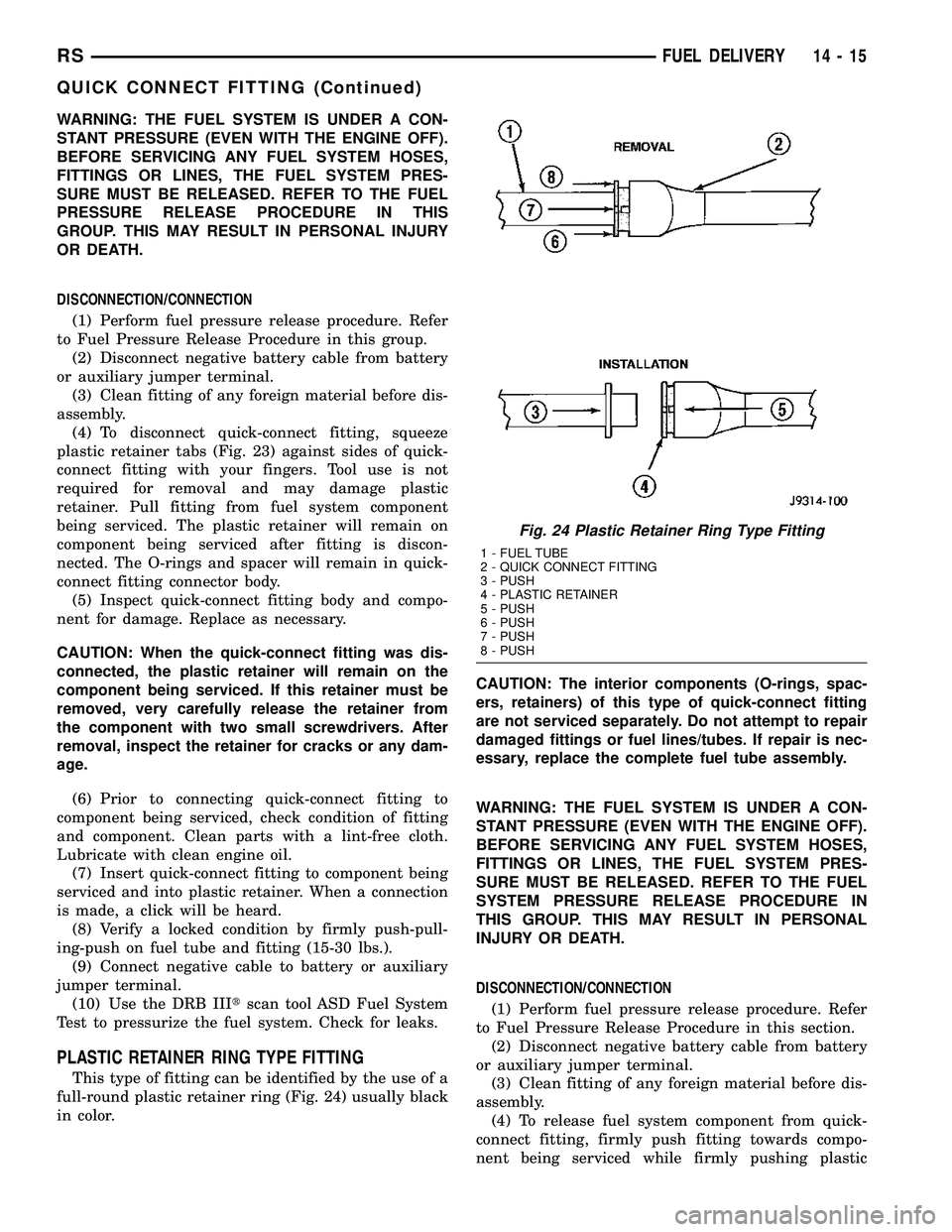
PLASTIC RETAINER RING TYPE FITTING
This type of fitting can be identified by the use of a
full-round plastic retainer ring (Fig. 24) usually black
in color.CAUTION: The interior components (O-rings, spac-
ers, retainers) of this type of quick-connect fitting
are not serviced separately. Do not attempt to repair
damaged fittings or fuel lines/tubes. If repair is nec-
essary, replace the complete fuel tube assembly.
WARNING: THE FUEL SYSTEM IS UNDER A CON-
STANT PRESSURE (EVEN WITH THE ENGINE OFF).
BEFORE SERVICING ANY FUEL SYSTEM HOSES,
FITTINGS OR LINES, THE FUEL SYSTEM PRES-
SURE MUST BE RELEASED. REFER TO THE FUEL
SYSTEM PRESSURE RELEASE PROCEDURE IN
THIS GROUP. THIS MAY RESULT IN PERSONAL
INJURY OR DEATH.
DISCONNECTION/CONNECTION
(1) Perform fuel pressure release procedure. Refer
to Fuel Pressure Release Procedure in this section.
(2) Disconnect negative battery cable from battery
or auxiliary jumper terminal.
(3) Clean fitting of any foreign material before dis-
assembly.
(4) To release fuel system component from quick-
connect fitting, firmly push fitting towards compo-
nent being serviced while firmly pushing plastic
Fig. 24 Plastic Retainer Ring Type Fitting
1 - FUEL TUBE
2 - QUICK CONNECT FITTING
3 - PUSH
4 - PLASTIC RETAINER
5 - PUSH
6 - PUSH
7 - PUSH
8 - PUSH
RSFUEL DELIVERY14-15
QUICK CONNECT FITTING (Continued)
Page 1572 of 2585
OPERATION
Turning of the steering wheel is converted into lin-
ear (side-to-side) travel through the meshing of the
helical pinion teeth with the rack teeth in the steer-
ing gear. This travel pushes and pulls the tie rods to
change the direction of the vehicle's front wheels.
Power assist steering provided by the power steer-
ing pump is controlled by an open center, rotary type
control valve which directs oil from the pump to
either side of the integral rack piston upon demand.
Road feel is controlled by the diameter of a torsion
bar which initially steers the vehicle. As required
steering effort increases, as in a turn, the torsion bar
twists, causing relative rotary motion between the
rotary valve body and the valve spool. This move-
ment directs oil behind the integral rack piston
which, in turn, builds hydraulic pressure and assists
in the turning effort.
Manual steering control of the vehicle can be main-
tained if power steering assist is lost. However,
under this condition, steering effort is significantly
increased.
WARNING
WARNINGS AND CAUTIONS
WARNING: POWER STEERING FLUID, ENGINE
PARTS AND EXHAUST SYSTEM MAY BE
EXTREMELY HOT IF ENGINE HAS BEEN RUNNING.
DO NOT START ENGINE WITH ANY LOOSE OR DIS-
CONNECTED HOSES. DO NOT ALLOW HOSES TO
TOUCH HOT EXHAUST MANIFOLD OR CATALYST.
WARNING: FLUID LEVEL SHOULD BE CHECKED
WITH THE ENGINE OFF TO PREVENT PERSONAL
INJURY FROM MOVING PARTS.
CAUTION: When the system is open, cap all open
ends of the hoses, power steering pump fittings or
power steering gear ports to prevent entry of for-
eign material into the components.
REMOVAL
REMOVAL - LHD GEAR
(1) Remove cap from power steering fluid reser-
voir.
(2) Using a siphon pump, remove as much fluid as
possible from the power steering fluid reservoir.Use
care not to damage the filter mesh below the
fluid surface.
CAUTION: Locking the steering column in the
straight-ahead position will prevent the clockspring
from being accidentally over-extended when the
steering column is disconnected from the interme-
diate steering coupler.
(3) Position the steering wheel in the STRAIGHT-
AHEAD position. Lock the steering wheel in place
using a steering wheel holding tool.
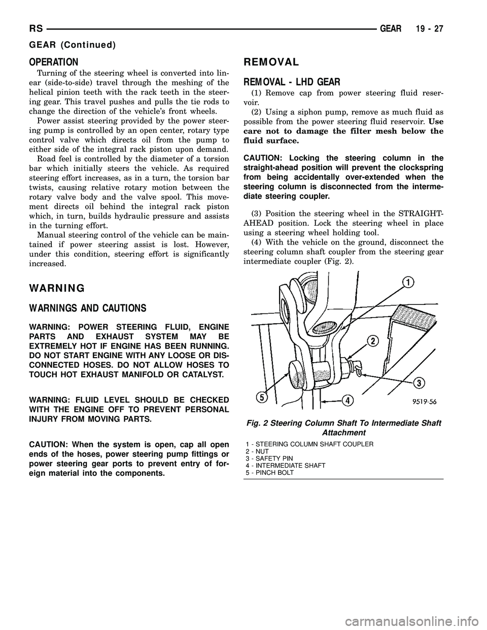
(4) With the vehicle on the ground, disconnect the
steering column shaft coupler from the steering gear
intermediate coupler (Fig. 2).
Fig. 2 Steering Column Shaft To Intermediate Shaft
Attachment
1 - STEERING COLUMN SHAFT COUPLER
2 - NUT
3 - SAFETY PIN
4 - INTERMEDIATE SHAFT
5 - PINCH BOLT
RSGEAR19-27
GEAR (Continued)
Page 1600 of 2585
OPERATION
The Transfer Unit provides the power to the rear
wheels through a hypoid ring gear and pinion set.
DIAGNOSIS AND TESTING
SEAL IDENTIFICATION
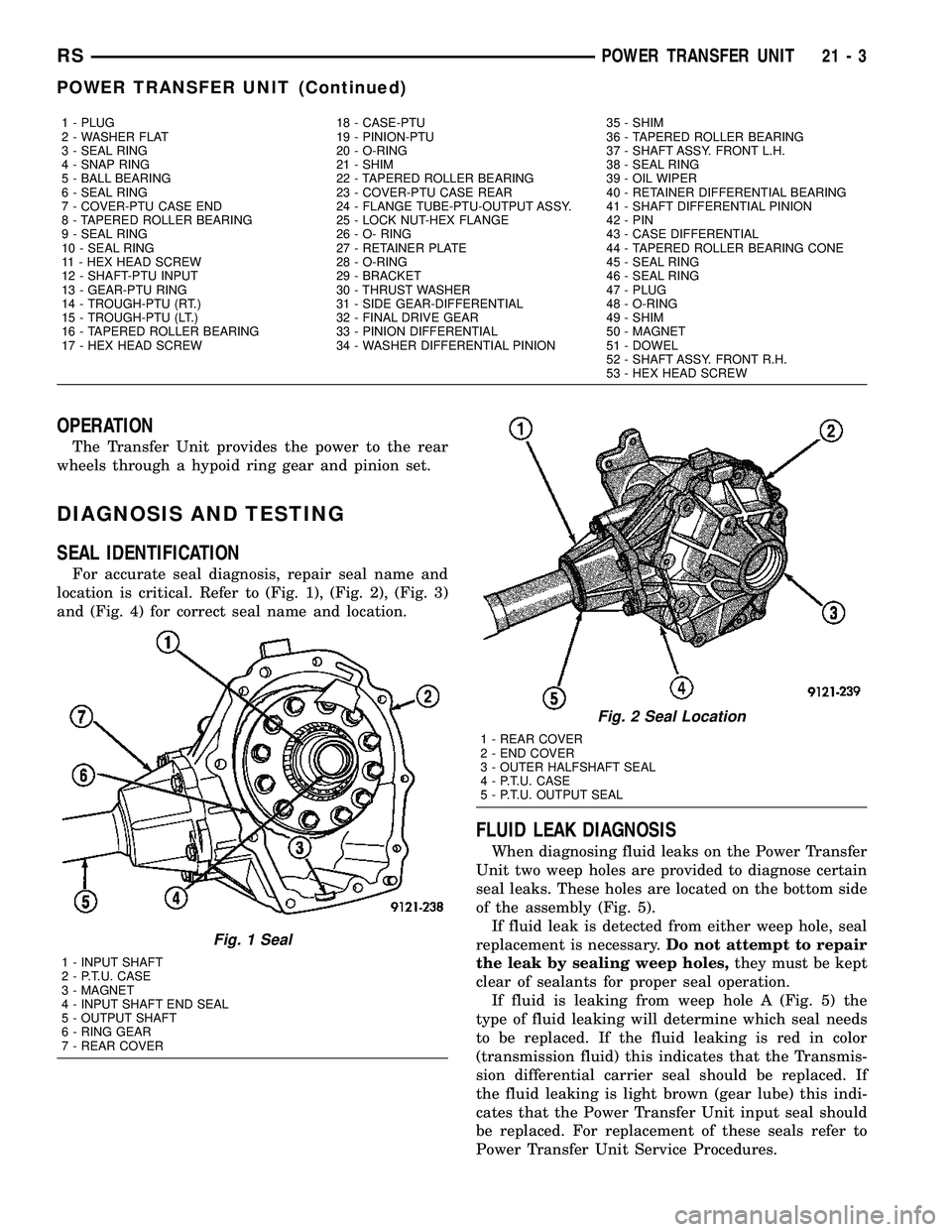
For accurate seal diagnosis, repair seal name and
location is critical. Refer to (Fig. 1), (Fig. 2), (Fig. 3)
and (Fig. 4) for correct seal name and location.
FLUID LEAK DIAGNOSIS
When diagnosing fluid leaks on the Power Transfer
Unit two weep holes are provided to diagnose certain
seal leaks. These holes are located on the bottom side
of the assembly (Fig. 5).
If fluid leak is detected from either weep hole, seal
replacement is necessary.Do not attempt to repair
the leak by sealing weep holes,they must be kept
clear of sealants for proper seal operation.
If fluid is leaking from weep hole A (Fig. 5) the
type of fluid leaking will determine which seal needs
to be replaced. If the fluid leaking is red in color
(transmission fluid) this indicates that the Transmis-
sion differential carrier seal should be replaced. If
the fluid leaking is light brown (gear lube) this indi-
cates that the Power Transfer Unit input seal should
be replaced. For replacement of these seals refer to
Power Transfer Unit Service Procedures.
1 - PLUG 18 - CASE-PTU 35 - SHIM
2 - WASHER FLAT 19 - PINION-PTU 36 - TAPERED ROLLER BEARING
3 - SEAL RING 20 - O-RING 37 - SHAFT ASSY. FRONT L.H.
4 - SNAP RING 21 - SHIM 38 - SEAL RING
5 - BALL BEARING 22 - TAPERED ROLLER BEARING 39 - OIL WIPER
6 - SEAL RING 23 - COVER-PTU CASE REAR 40 - RETAINER DIFFERENTIAL BEARING
7 - COVER-PTU CASE END 24 - FLANGE TUBE-PTU-OUTPUT ASSY. 41 - SHAFT DIFFERENTIAL PINION
8 - TAPERED ROLLER BEARING 25 - LOCK NUT-HEX FLANGE 42 - PIN
9 - SEAL RING 26 - O- RING 43 - CASE DIFFERENTIAL
10 - SEAL RING 27 - RETAINER PLATE 44 - TAPERED ROLLER BEARING CONE
11 - HEX HEAD SCREW 28 - O-RING 45 - SEAL RING
12 - SHAFT-PTU INPUT 29 - BRACKET 46 - SEAL RING
13 - GEAR-PTU RING 30 - THRUST WASHER 47 - PLUG
14 - TROUGH-PTU (RT.) 31 - SIDE GEAR-DIFFERENTIAL 48 - O-RING
15 - TROUGH-PTU (LT.) 32 - FINAL DRIVE GEAR 49 - SHIM
16 - TAPERED ROLLER BEARING 33 - PINION DIFFERENTIAL 50 - MAGNET
17 - HEX HEAD SCREW 34 - WASHER DIFFERENTIAL PINION 51 - DOWEL
52 - SHAFT ASSY. FRONT R.H.
53 - HEX HEAD SCREW
Fig. 1 Seal
1 - INPUT SHAFT
2 - P.T.U. CASE
3 - MAGNET
4 - INPUT SHAFT END SEAL
5 - OUTPUT SHAFT
6 - RING GEAR
7 - REAR COVER
Fig. 2 Seal Location
1 - REAR COVER
2 - END COVER
3 - OUTER HALFSHAFT SEAL
4 - P.T.U. CASE
5 - P.T.U. OUTPUT SEAL
RSPOWER TRANSFER UNIT21-3
POWER TRANSFER UNIT (Continued)