2004 CHRYSLER VOYAGER oil type
[x] Cancel search: oil typePage 1388 of 2585

(47) Connect the radiator upper hose.
(48) Connect the heater hoses. Remove pinch-off
pliers from the rear heater hoses (if equipped).
(49) Install the radiator upper support crossmem-
ber (Refer to 23 - BODY/EXTERIOR/GRILLE OPEN-
ING REINFORCEMENT - INSTALLATION).
(50) Install the wiper module (Refer to 8 - ELEC-
TRICAL/WIPERS/WASHERS/WIPER MODULE -
INSTALLATION).
(51) Connect the fuel line to fuel rail (Refer to 14 -
FUEL SYSTEM/FUEL DELIVERY/FUEL LINES -
STANDARD PROCEDURE).
(52) Install the air cleaner and hoses.
(53) Install new oil filter. Fill engine crankcase
with proper oil to correct level.
(54) Connect negative cable to battery.
(55) Fill the cooling system (Refer to 7 - COOLING
- STANDARD PROCEDURE).
(56) Start engine and run until operating temper-
ature is reached.
(57) Adjust transmission linkage, if necessary.
SPECIFICATIONS
3.3/3.8L ENGINE
DESCRIPTION SPECIFICATION
General Specification
Type 60É V-6 Engine
Number of Cylinders 6
Displacement
Ð3.3L 3.3 Liters
(201 cu. in.)
Ð3.8L 3.8 Liters
(231 cu. in.)
Bore
Ð3.3L 93.0 mm
(3.66 in.)
Ð3.8L 96.0 mm
(3.779 in.)
Stroke
Ð3.3L 81.0 mm
(3.188 in.)
Ð3.8L 87.0 mm
(3.425 in.)
Compression Ratio
Ð3.3L 9.35:1
Ð3.8L 9.6:1
DESCRIPTION SPECIFICATION
Firing Order 1-2-3-4-5-6
Cylinder Number (Front
to Rear)
ÐFront Bank 2,4,6
ÐRear Bank 1,3,5
Compression PressureÐ
Minimum689.5 kPa
(100 psi)
Max. Variation Between
Cylinders25%
Cylinder Block
Cylinder Bore Diameter
(Standard)
Ð3.3L 92.993±93.007 mm
(3.661±3.6617 in.)
Ð3.8L 95.993±96.007 mm
(3.7792±3.780 in.)
Out-of-Round (Service
Limits)0.076 mm
(0.003 in.)
Taper (Service Limits) 0.051 mm
(0.002 in.)
Lifter Bore Diameter 22.980±23.010 mm
(0.905±0.906 in.)
Deck Surface Flatness
(Max.)0.1 mm
(0.004 in.)
Pistons
Piston Diameter
Ð3.3L ÐMeasured 39.8
mm (1.567 in.) from
piston top92.968±92.998 mm
(3.660±3.661 in.)
Ð3.8L ÐMeasured 33.01
mm (1.30 in.) from piston
top95.968±95.998 mm
(3.778±3.779 in.)
Clearance in Bore @
Size Location (New)-0.005±0.039 mm
(-0.0002±0.0015 in.)
Weight
Ð3.3L 362 5 grams
(12.77 0.1764 oz.)
Ð3.8L 426 5 grams
(15.03 0.1764 oz.)
Piston Pins
Type Press Fit in Rod
(Serviced as an
Assembly)
RSENGINE 3.3/3.8L9-91
ENGINE 3.3/3.8L (Continued)
Page 1410 of 2585
CYLINDER BORE
NOTE: The cylinder bores should be measured at
normal room temperature, 21ÉC (70ÉF).
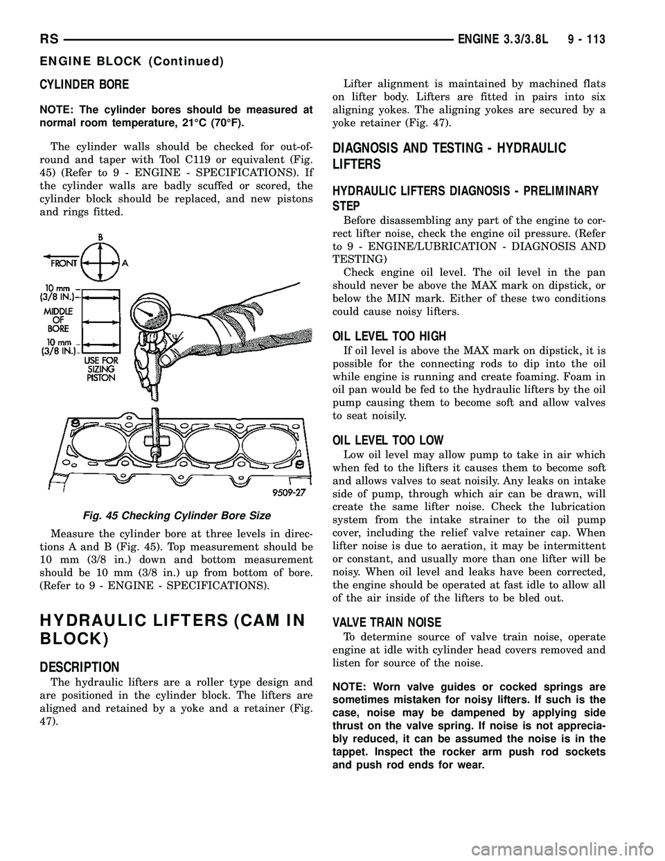
The cylinder walls should be checked for out-of-
round and taper with Tool C119 or equivalent (Fig.
45) (Refer to 9 - ENGINE - SPECIFICATIONS). If
the cylinder walls are badly scuffed or scored, the
cylinder block should be replaced, and new pistons
and rings fitted.
Measure the cylinder bore at three levels in direc-
tions A and B (Fig. 45). Top measurement should be
10 mm (3/8 in.) down and bottom measurement
should be 10 mm (3/8 in.) up from bottom of bore.
(Refer to 9 - ENGINE - SPECIFICATIONS).
HYDRAULIC LIFTERS (CAM IN
BLOCK)
DESCRIPTION
The hydraulic lifters are a roller type design and
are positioned in the cylinder block. The lifters are
aligned and retained by a yoke and a retainer (Fig.
47).Lifter alignment is maintained by machined flats
on lifter body. Lifters are fitted in pairs into six
aligning yokes. The aligning yokes are secured by a
yoke retainer (Fig. 47).
DIAGNOSIS AND TESTING - HYDRAULIC
LIFTERS
HYDRAULIC LIFTERS DIAGNOSIS - PRELIMINARY
STEP
Before disassembling any part of the engine to cor-
rect lifter noise, check the engine oil pressure. (Refer
to 9 - ENGINE/LUBRICATION - DIAGNOSIS AND
TESTING)
Check engine oil level. The oil level in the pan
should never be above the MAX mark on dipstick, or
below the MIN mark. Either of these two conditions
could cause noisy lifters.
OIL LEVEL TOO HIGH
If oil level is above the MAX mark on dipstick, it is
possible for the connecting rods to dip into the oil
while engine is running and create foaming. Foam in
oil pan would be fed to the hydraulic lifters by the oil
pump causing them to become soft and allow valves
to seat noisily.
OIL LEVEL TOO LOW
Low oil level may allow pump to take in air which
when fed to the lifters it causes them to become soft
and allows valves to seat noisily. Any leaks on intake
side of pump, through which air can be drawn, will
create the same lifter noise. Check the lubrication
system from the intake strainer to the oil pump
cover, including the relief valve retainer cap. When
lifter noise is due to aeration, it may be intermittent
or constant, and usually more than one lifter will be
noisy. When oil level and leaks have been corrected,
the engine should be operated at fast idle to allow all
of the air inside of the lifters to be bled out.
VALVE TRAIN NOISE
To determine source of valve train noise, operate
engine at idle with cylinder head covers removed and
listen for source of the noise.
NOTE: Worn valve guides or cocked springs are
sometimes mistaken for noisy lifters. If such is the
case, noise may be dampened by applying side
thrust on the valve spring. If noise is not apprecia-
bly reduced, it can be assumed the noise is in the
tappet. Inspect the rocker arm push rod sockets
and push rod ends for wear.
Fig. 45 Checking Cylinder Bore Size
RSENGINE 3.3/3.8L9 - 113
ENGINE BLOCK (Continued)
Page 1433 of 2585
LUBRICATION
DESCRIPTION
The lubrication system is a full flow filtration pres-
sure feed type. The oil pump is mounted in the tim-
ing chain cover and is driven by the crankshaft
OPERATION
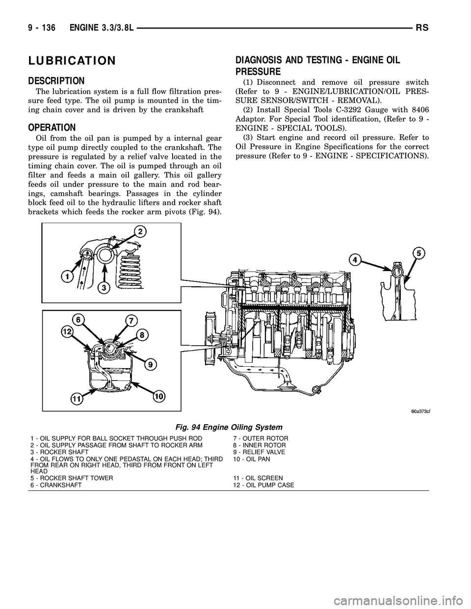
Oil from the oil pan is pumped by a internal gear
type oil pump directly coupled to the crankshaft. The
pressure is regulated by a relief valve located in the
timing chain cover. The oil is pumped through an oil
filter and feeds a main oil gallery. This oil gallery
feeds oil under pressure to the main and rod bear-
ings, camshaft bearings. Passages in the cylinder
block feed oil to the hydraulic lifters and rocker shaft
brackets which feeds the rocker arm pivots (Fig. 94).
DIAGNOSIS AND TESTING - ENGINE OIL
PRESSURE
(1) Disconnect and remove oil pressure switch
(Refer to 9 - ENGINE/LUBRICATION/OIL PRES-
SURE SENSOR/SWITCH - REMOVAL).
(2) Install Special Tools C-3292 Gauge with 8406
Adaptor. For Special Tool identification, (Refer to 9 -
ENGINE - SPECIAL TOOLS).
(3) Start engine and record oil pressure. Refer to
Oil Pressure in Engine Specifications for the correct
pressure (Refer to 9 - ENGINE - SPECIFICATIONS).
Fig. 94 Engine Oiling System
1 - OIL SUPPLY FOR BALL SOCKET THROUGH PUSH ROD 7 - OUTER ROTOR
2 - OIL SUPPLY PASSAGE FROM SHAFT TO ROCKER ARM 8 - INNER ROTOR
3 - ROCKER SHAFT 9 - RELIEF VALVE
4 - OIL FLOWS TO ONLY ONE PEDASTAL ON EACH HEAD; THIRD
FROM REAR ON RIGHT HEAD, THIRD FROM FRONT ON LEFT
HEAD10 - OIL PAN
5 - ROCKER SHAFT TOWER 11 - OIL SCREEN
6 - CRANKSHAFT 12 - OIL PUMP CASE
9 - 136 ENGINE 3.3/3.8LRS
Page 1434 of 2585
OIL
STANDARD PROCEDURE
STANDARD PROCEDURE - ENGINE OIL AND
FILTER CHANGE
Change engine oil at mileage and time intervals
described in the Maintenance Schedule. (Refer to
LUBRICATION & MAINTENANCE/MAINTE-
NANCE SCHEDULES - DESCRIPTION)
WARNING: NEW OR USED ENGINE OIL CAN BE
IRRITATING TO THE SKIN. AVOID PROLONGED OR
REPEATED SKIN CONTACT WITH ENGINE OIL.
CONTAMINANTS IN USED ENGINE OIL, CAUSED BY
INTERNAL COMBUSTION, CAN BE HAZARDOUS TO
YOUR HEALTH. THOROUGHLY WASH EXPOSED
SKIN WITH SOAP AND WATER. DO NOT WASH
SKIN WITH GASOLINE, DIESEL FUEL, THINNER, OR
SOLVENTS, HEALTH PROBLEMS CAN RESULT. DO
NOT POLLUTE, DISPOSE OF USED ENGINE OIL
PROPERLY. CONTACT YOUR DEALER OR GOVERN-
MENT AGENCY FOR LOCATION OF COLLECTION
CENTER IN YOUR AREA.
Run engine until achieving normal operating tem-
perature.
(1) Position the vehicle on a level surface and turn
engine off.
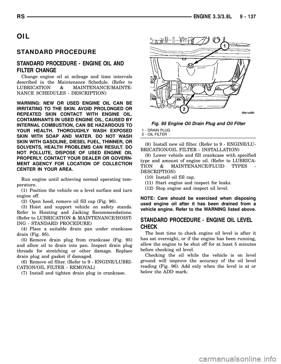
(2) Open hood, remove oil fill cap (Fig. 96).
(3) Hoist and support vehicle on safety stands.
Refer to Hoisting and Jacking Recommendations.
(Refer to LUBRICATION & MAINTENANCE/HOIST-
ING - STANDARD PROCEDURE)
(4) Place a suitable drain pan under crankcase
drain (Fig. 95).
(5) Remove drain plug from crankcase (Fig. 95)
and allow oil to drain into pan. Inspect drain plug
threads for stretching or other damage. Replace
drain plug and gasket if damaged.
(6) Remove oil filter. (Refer to 9 - ENGINE/LUBRI-
CATION/OIL FILTER - REMOVAL)
(7) Install and tighten drain plug in crankcase.(8) Install new oil filter. (Refer to 9 - ENGINE/LU-
BRICATION/OIL FILTER - INSTALLATION)
(9) Lower vehicle and fill crankcase with specified
type and amount of engine oil. (Refer to LUBRICA-
TION & MAINTENANCE/FLUID TYPES -
DESCRIPTION)
(10) Install oil fill cap.
(11) Start engine and inspect for leaks.
(12) Stop engine and inspect oil level.
NOTE: Care should be exercised when disposing
used engine oil after it has been drained from a
vehicle engine. Refer to the WARNING listed above.
STANDARD PROCEDURE - ENGINE OIL LEVEL
CHECK
The best time to check engine oil level is after it
has sat overnight, or if the engine has been running,
allow the engine to be shut off for at least 5 minutes
before checking oil level.
Checking the oil while the vehicle is on level
ground will improve the accuracy of the oil level
reading (Fig. 96). Add only when the level is at or
below the ADD mark.
Fig. 95 Engine Oil Drain Plug and Oil Filter
1 - DRAIN PLUG
2 - OIL FILTER
RSENGINE 3.3/3.8L9 - 137
Page 1435 of 2585

OIL COOLER & LINES
DESCRIPTION
An engine oil cooler is used on 3.3/3.8L engines
(Heavy Duty Cooling Only) (Fig. 98). The cooler is a
coolant-to-oil type and mounted between the oil filter
and engine block.
OPERATION
Engine oil travels from the oil filter and into the
oil cooler. Engine oil then exits the cooler into the
main gallery. Engine coolant flows into the cooler
from the heater return tube and exits into the water
pump inlet.
REMOVAL
(1) Drain cooling system (Refer to 7 - COOLING -
STANDARD PROCEDURE - COOLING SYSTEM
DRAINING).
(2) Disconnect oil cooler inlet and outlet hoses
(Fig. 97).
(3) Remove oil filter.
(4) Remove oil cooler attachment fitting (Fig. 98).
(5) Remove oil cooler.
INSTALLATION
(1) Lubricate seal and position oil cooler to connec-
tor fitting on oil filter adapter (Fig. 98).NOTE: Position the flat side of oil cooler parallel to
oil pan rail.
(2) Install oil cooler attachment fitting and tighten
to 27 N´m (20 ft. lbs.) (Fig. 98).
(3) Install oil filter.
(4) Connect oil cooler inlet and outlet hoses (Fig.
97).
Fig. 96 Engine Oil Level Dipstick and Fill Locations
1 - COOLANT RECOVERY CONTAINER 3 - ENGINE OIL LEVEL DIPSTICK
2 - ENGINE OIL FILL CAP 4 - RADIATOR PRESSURE CAP
Fig. 97 Engine Oil Cooler Hoses
1 - OIL COOLER INLET TUBE
2 - INLET HOSE
3 - OIL COOLER OUTLET TUBE
4 - OUTLET HOSE
5 - WATER PUMP INLET TUBE
9 - 138 ENGINE 3.3/3.8LRS
OIL (Continued)
Page 1467 of 2585
CONNECTING RODS
DESCRIPTION SPECIFICATION
Metric Standard
Bearing
Clearance0.019-0.065
mm.0.017-0.020 in.
Wear Limit 0.074 mm 0.003 in.
Side Clearance 0.13-0.32 mm 0.005-0.013 in.
Wear Limit 0.38 mm 0.015 in.
PISTONS
DESCRIPTION SPECIFICATION
Metric Standard
Piston Diameter
3.3L-Measured
39.8 mm (1.567
in) From Piston
To p92.968-92.998
mm.3.660-3.661 in.
Piston Diameter
3.8L-Measured
33.01 mm (1.30
in) From Piston
To p95.968-95.998
mm.3.778-3.779 in.
Clearance in
Bore @ Size
Location (New)-0.005-0.039
mm-0.0002±0.0015
in.
Weight 3.3L 362 5 grams 12.77 0.1764
oz.
Weight 3.8L 426 5 grams 15.03 0.1764
oz.
PISTON PINS
DESCRIPTION SPECIFICATION
Metric Standard
Type Press Fit in Rod (Serviced as a
Assembly)
Clearance in
Piston @ 21C
(70ÉF)0.006-0.019
mm0.0002-0.0007
in.
Clearance in
Connecting RodInterference Fit
Diameter 22.87-22.88
mm0.9007-0.9009
in.
Length 3.3L 67.25-67.75
mm2.648-2.667 in.
Length 3.8L 71.25-71.75
mm2.805-2.824 in.
PISTON RINGS
DESCRIPTION SPECIFICATION
Metric Standard
Ring End Gap
To p
Compression
Ring0.18-0.38 mm 0.007-0.015 in.
Second
Compression
Ring0.28-0.57 mm 0.011-0.022 in.
Oil Control
(Steel Rails)0.23-0.78 mm 0.009-0.030 in.
Wear Limit-
Compression
Rings1.0 mm 0.039 in.
Wear Limit-Oil
Control Steel
Rails1.88 mm 0.074 in.
Ring Side
Clearance
To p
Compression
Ring 3.3L0.030-0.080
mm0.0012-0.0031
in.
To p
Compression
Ring 3.8L0.030-0.069
mm0.0012-0.0027
in.
Second
Compression
Ring 3.3L0.030-0.095
mm0.0012-0.0037
in.
Second
Compression
Ring 3.8L0.041-0.085
mm0.0016-0.0033
in.
Oil Ring (Steel
Ring)0.039-0.200
mm0.0015-0.0078
in.
Wear Limit- Top
Ring0.10 mm 0.004 in.
Wear Limit-2nd
Ring0.13 mm 0.005
Wear Limit Oil
Ring Pack0.266 mm 0.009
Ring Width-Top
Compression
Ring 3.3L1.46-1.49 mm 0.0575-0.058 in.
Ring Width-Top
Compression
Ring 3.8L1.175-1.190
mm0.0462-0.0468
9s - 12 ENGINE 3.3/3.8L SUPPLEMENTRS
ENGINE 3.3/3.8L SUPPLEMENT (Continued)
Page 1468 of 2585
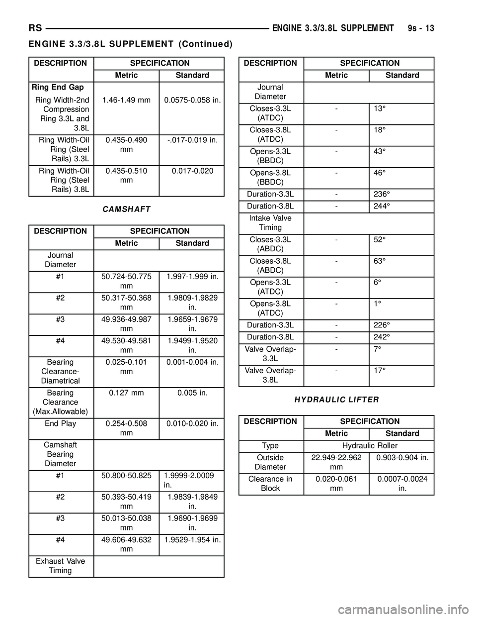
DESCRIPTION SPECIFICATION
Metric Standard
Ring End Gap
Ring Width-2nd
Compression
Ring 3.3L and
3.8L1.46-1.49 mm 0.0575-0.058 in.
Ring Width-Oil
Ring (Steel
Rails) 3.3L0.435-0.490
mm-.017-0.019 in.
Ring Width-Oil
Ring (Steel
Rails) 3.8L0.435-0.510
mm0.017-0.020
CAMSHAFT
DESCRIPTION SPECIFICATION
Metric Standard
Journal
Diameter
#1 50.724-50.775
mm1.997-1.999 in.
#2 50.317-50.368
mm1.9809-1.9829
in.
#3 49.936-49.987
mm1.9659-1.9679
in.
#4 49.530-49.581
mm1.9499-1.9520
in.
Bearing
Clearance-
Diametrical0.025-0.101
mm0.001-0.004 in.
Bearing
Clearance
(Max.Allowable)0.127 mm 0.005 in.
End Play 0.254-0.508
mm0.010-0.020 in.
Camshaft
Bearing
Diameter
#1 50.800-50.825 1.9999-2.0009
in.
#2 50.393-50.419
mm1.9839-1.9849
in.
#3 50.013-50.038
mm1.9690-1.9699
in.
#4 49.606-49.632
mm1.9529-1.954 in.
Exhaust Valve
Timing
DESCRIPTION SPECIFICATION
Metric Standard
Journal
Diameter
Closes-3.3L
(ATDC)- 13É
Closes-3.8L
(ATDC)- 18É
Opens-3.3L
(BBDC)- 43É
Opens-3.8L
(BBDC)- 46É
Duration-3.3L - 236É
Duration-3.8L - 244É
Intake Valve
Timing
Closes-3.3L
(ABDC)- 52É
Closes-3.8L
(ABDC)- 63É
Opens-3.3L
(ATDC)-6É
Opens-3.8L
(ATDC)-1É
Duration-3.3L - 226É
Duration-3.8L - 242É
Valve Overlap-
3.3L-7É
Valve Overlap-
3.8L- 17É
HYDRAULIC LIFTER
DESCRIPTION SPECIFICATION
Metric Standard
Type Hydraulic Roller
Outside
Diameter22.949-22.962
mm0.903-0.904 in.
Clearance in
Block0.020-0.061
mm0.0007-0.0024
in.
RSENGINE 3.3/3.8L SUPPLEMENT9s-13
ENGINE 3.3/3.8L SUPPLEMENT (Continued)
Page 1470 of 2585
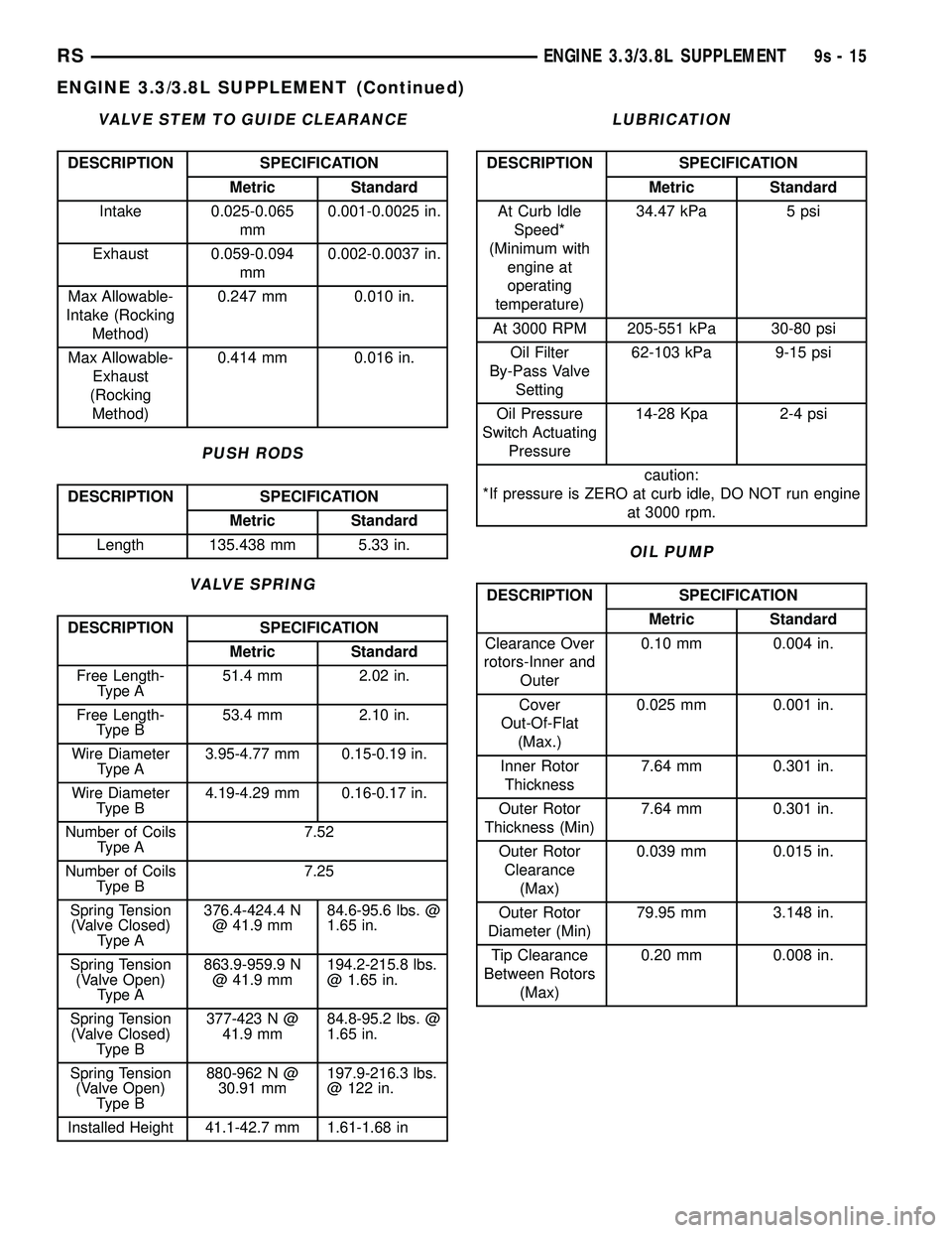
VALVE STEM TO GUIDE CLEARANCE
DESCRIPTION SPECIFICATION
Metric Standard
Intake 0.025-0.065
mm0.001-0.0025 in.
Exhaust 0.059-0.094
mm0.002-0.0037 in.
Max Allowable-
Intake (Rocking
Method)0.247 mm 0.010 in.
Max Allowable-
Exhaust
(Rocking
Method)0.414 mm 0.016 in.
PUSH RODS
DESCRIPTION SPECIFICATION
Metric Standard
Length 135.438 mm 5.33 in.
VALVE SPRING
DESCRIPTION SPECIFICATION
Metric Standard
Free Length-
Type A51.4 mm 2.02 in.
Free Length-
Type B53.4 mm 2.10 in.
Wire Diameter
Type A3.95-4.77 mm 0.15-0.19 in.
Wire Diameter
Type B4.19-4.29 mm 0.16-0.17 in.
Number of Coils
Type A7.52
Number of Coils
Type B7.25
Spring Tension
(Valve Closed)
Type A376.4-424.4 N
@ 41.9 mm84.6-95.6 lbs. @
1.65 in.
Spring Tension
(Valve Open)
Type A863.9-959.9 N
@ 41.9 mm194.2-215.8 lbs.
@ 1.65 in.
Spring Tension
(Valve Closed)
Type B377-423 N @
41.9 mm84.8-95.2 lbs. @
1.65 in.
Spring Tension
(Valve Open)
Type B880-962 N @
30.91 mm197.9-216.3 lbs.
@ 122 in.
Installed Height 41.1-42.7 mm 1.61-1.68 in
LUBRICATION
DESCRIPTION SPECIFICATION
Metric Standard
At Curb Idle
Speed*
(Minimum with
engine at
operating
temperature)34.47 kPa 5 psi
At 3000 RPM 205-551 kPa 30-80 psi
Oil Filter
By-Pass Valve
Setting62-103 kPa 9-15 psi
Oil Pressure
Switch Actuating
Pressure14-28 Kpa 2-4 psi
caution:
*If pressure is ZERO at curb idle, DO NOT run engine
at 3000 rpm.
OIL PUMP
DESCRIPTION SPECIFICATION
Metric Standard
Clearance Over
rotors-Inner and
Outer0.10 mm 0.004 in.
Cover
Out-Of-Flat
(Max.)0.025 mm 0.001 in.
Inner Rotor
Thickness7.64 mm 0.301 in.
Outer Rotor
Thickness (Min)7.64 mm 0.301 in.
Outer Rotor
Clearance
(Max)0.039 mm 0.015 in.
Outer Rotor
Diameter (Min)79.95 mm 3.148 in.
Tip Clearance
Between Rotors
(Max)0.20 mm 0.008 in.
RSENGINE 3.3/3.8L SUPPLEMENT9s-15
ENGINE 3.3/3.8L SUPPLEMENT (Continued)