2004 CHRYSLER VOYAGER oil type
[x] Cancel search: oil typePage 1963 of 2585
PRELOAD ADJUSTMENT W/O SHIM(1) Remove the bearing cup from the differential
bearing retainer using Miller special Tool 6062A. (2) Remove existing shim from under bearing cup.
(3) Reinstall the bearing cup into the retainer
using Miller Special Tool 6061, and C-4171.
NOTE: Oil baffle is not required when making the
shim calculation.
(4) Install the bearing retainer into the case.
Torque bolts to 28 N ²m (250 in. lbs.).
(5) Position the transaxle assembly vertically on
the support stand and install Miller Special Tool
L-4436-A into the bearing retainer. (6) Rotate the differential at least one full revolu-
tion to ensure the tapered roller bearings are fully
seated. (7) Attach a dial indicator to the case and zero the
dial. Place the tip on the end of Special Tool
L-4436-A. (8) Place a large screwdriver to each side of the
ring gear and lift. Check the dial indicator for the
amount of end play.
CAUTION: Do not damage the transaxle case and/or
differential retainer sealing surface.
(9) Using the end play measurement that was
determined, add 0.18mm (0.007 inch). This should
give you between 5 and 18 inch pounds of bearing
preload. Refer to the Differential Bearing Shim Chart
to determine which shim to use. (10) Remove the differential bearing retainer.
Remove the bearing cup. (11) Install the oil baffle. Install the proper shim
combination under the bearing cup. (12) Install the differential bearing retainer. Seal
the retainer to the housing with Mopar tSilicone
Rubber Adhesive Sealant. Torque bolts to 28 N ²m
(250 in. lbs.). (13) Using Miller Special Tool L-4436-A and an
inch-pound torque wrench, check the turning torque
of the differential (Fig. 186). The turning torque
should be between 5-18 inch-pounds.
NOTE: If turning torque is too high install a 0.05mm
(0.002 inch) thicker shim. If the turning torque is too
low, install a 0.05mm (0.002 inch) thinner shim.
Repeat until 5-18 inch-pounds of turning torque is
obtained.FLUID
STANDARD PROCEDURE
FLUID LEVEL AND CONDITION CHECK
NOTE: Only transmission fluid of the type labeled
Mopar ATF+4 (Automatic Transmission Fluid)
should be used in this transaxle.
FLUID LEVEL CHECK
The transmission sump has a fluid level indicator
(dipstick) to check oil similar to most automatic
transmissions. It is located on the left side of the
engine. Be sure to wipe all dirt from dipstick handle
before removing. The torque converter fills in both the P Park and N
Neutral positions. Place the selector lever in P Park
to be sure that the fluid level check is accurate. The
engine should be running at idle speed for at
least one minute, with the vehicle on level
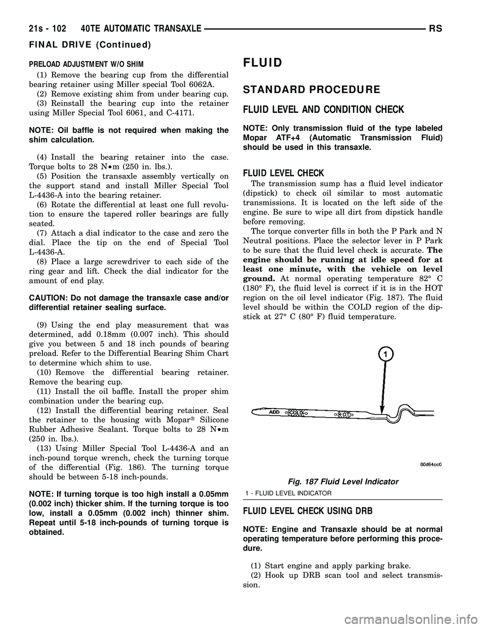
ground. At normal operating temperature 82É C
(180É F), the fluid level is correct if it is in the HOT
region on the oil level indicator (Fig. 187). The fluid
level should be within the COLD region of the dip-
stick at 27É C (80É F) fluid temperature.
FLUID LEVEL CHECK USING DRB
NOTE: Engine and Transaxle should be at normal
operating temperature before performing this proce-
dure.
(1) Start engine and apply parking brake.
(2) Hook up DRB scan tool and select transmis-
sion.
Fig. 187 Fluid Level Indicator
1 - FLUID LEVEL INDICATOR
21s - 102 40TE AUTOMATIC TRANSAXLERS
FINAL DRIVE (Continued)
Page 1965 of 2585

STANDARD PROCEDURE - FLUID AND FILTER
SERVICE
NOTE: Refer to the maintenance schedules in
LUBRICATION and MAINTENANCE, or the vehicle
owner's manual, for the recommended maintenance
(fluid/filter change) intervals for this transaxle.
NOTE: Only fluids of the type labeled MoparTATF+4
should be used. A filter change should be made at
the time of the transmission oil change. The magnet
(on the inside of the oil pan) should also be cleaned
with a clean, dry cloth.
NOTE: If the transaxle is disassembled for any rea-
son, the fluid and filter should be changed.
FLUID/FILTER SERVICE (RECOMMENDED)
(1) Raise vehicle on a hoist. Refer to LUBRICA-
TION and MAINTENANCE for proper procedures.
Place a drain container with a large opening, under
transaxle oil pan. (2) Remove both engine mount-to-engine cross-
member cradle nuts. Using suitable screw jack and
wood block, raise engine and transmission slightly to
facilitate transaxle oil pan removal and installation. (3) Loosen pan bolts and tap the pan at one corner
to break it loose allowing fluid to drain, then remove
the oil pan. (4) Install a new filter and o-ring on bottom of the
valve body (Fig. 189). (5) Clean the oil pan and magnet. Reinstall pan
using new Mopar Silicone Adhesive sealant. Tighten
oil pan bolts to 19 N´m (165 in. lbs.). (6) Pour four quarts of Mopar tATF+4 through the
dipstick opening. (7) Start engine and allow to idle for at least one
minute. Then, with parking and service brakes
applied, move selector lever momentarily to each
position, ending in the park or neutral position. (8) Check the transaxle fluid level and add an
appropriate amount to bring the transaxle fluid level
to 3mm (1/8 in.) below the lowest mark on the dip-
stick (Fig. 190).
(9) Recheck the fluid level after the transaxle has
reached normal operating temperature (180ÉF.). Refer
to Fluid Level and Condition Check for the proper
fluid fill procedure. (10) To prevent dirt from entering transaxle, make
certain that dipstick is fully seated into the dipstick
opening.
DIPSTICK TUBE FLUID SUCTION METHOD
(ALTERNATIVE)
(1) When performing the fluid suction method,
make sure the transaxle is at full operating temper-
ature. (2) To perform the dipstick tube fluid suction
method, use a suitable fluid suction device (VaculaŸ
or equivalent). (3) Insert the fluid suction line into the dipstick
tube.
NOTE: Verify that the suction line is inserted to the
lowest point of the transaxle oil pan. This will
ensure complete evacuation of the fluid in the pan.
(4) Follow the manufacturers recommended proce-
dure and evacuate the fluid from the transaxle.
Fig. 189 Filter and O-Ring
1 - OIL FILTER
2 - O-RING
Fig. 190 Fluid Level Indicator
1 - FLUID LEVEL INDICATOR
21s - 104 40TE AUTOMATIC TRANSAXLERS
FLUID (Continued)
Page 2115 of 2585
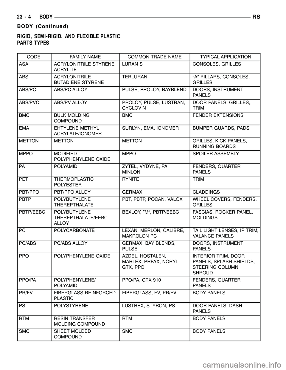
RIGID, SEMI-RIGID, AND FLEXIBLE PLASTIC
PARTS TYPES
CODE FAMILY NAME COMMON TRADE NAME TYPICAL APPLICATION
ASA ACRYLONITRILE STYRENE
ACRYLITELURAN S CONSOLES, GRILLES
ABS ACRYLONITRILE
BUTADIENE STYRENETERLURAN9A9PILLARS, CONSOLES,
GRILLES
ABS/PC ABS/PC ALLOY PULSE, PROLOY, BAYBLEND DOORS, INSTRUMENT
PANELS
ABS/PVC ABS/PV ALLOY PROLOY, PULSE, LUSTRAN,
CYCLOVINDOOR PANELS, GRILLES,
TRIM
BMC BULK MOLDING
COMPOUNDBMC FENDER EXTENSIONS
EMA EHTYLENE METHYL
ACRYLATE/IONOMERSURLYN, EMA, IONOMER BUMPER GUARDS, PADS
METTON METTON METTON GRILLES, KICK PANELS,
RUNNING BOARDS
MPPO MODIFIED
POLYPHENYLENE OXIDEMPPO SPOILER ASSEMBLY
PA POLYAMID ZYTEL, VYDYNE, PA,
MINLONFENDERS, QUARTER
PANELS
PET THERMOPLASTIC
POLYESTERRYNITE TRIM
PBT/PPO PBT/PPO ALLOY GERMAX CLADDINGS
PBTP POLYBUTYLENE
THEREPTHALATEPBT, PBTP, POCAN, VALOX WHEEL COVERS, FENDERS,
GRILLES
PBTP/EEBC POLYBUTYLENE
THEREPTHALATE/EEBC
ALLOYBEXLOY,9M9, PBTP/EEBC FASCIAS, ROCKER PANEL,
MOLDINGS
PC POLYCARBONATE LEXAN, MERLON, CALIBRE,
MAKROLON PCTAIL LIGHT LENSES, IP TRIM,
VALANCE PANELS
PC/ABS PC/ABS ALLOY GERMAX, BAY BLENDS,
PULSEDOORS, INSTRUMENT
PANELS
PPO POLYPHENYLENE OXIDE AZDEL, HOSTALEN,
MARLEX, PRFAX, NORYL,
GTX, PPOINTERIOR TRIM, DOOR
PANELS, SPLASH SHIELDS,
STEERING COLUMN
SHROUD
PPO/PA POLYPHENYLENE/
POLYAMIDPPO/PA, GTX 910 FENDERS, QUARTER
PANELS
PR/FV FIBERGLASS REINFORCED
PLASTICFIBERGLASS, FV, PR/FV BODY PANELS
PS POLYSTYRENE LUSTREX, STYRON, PS DOOR PANELS, DASH
PANELS
RTM RESIN TRANSFER
MOLDING COMPOUNDRTM BODY PANELS
SMC SHEET MOLDED
COMPOUNDSMC BODY PANELS
23 - 4 BODYRS
BODY (Continued)
Page 2118 of 2585
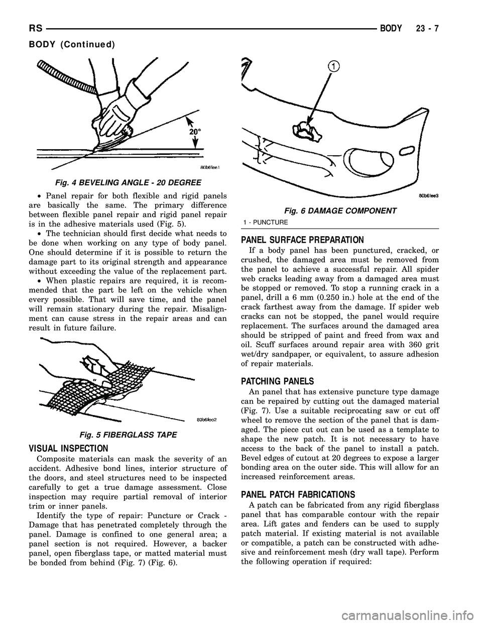
²Panel repair for both flexible and rigid panels
are basically the same. The primary difference
between flexible panel repair and rigid panel repair
is in the adhesive materials used (Fig. 5).
²The technician should first decide what needs to
be done when working on any type of body panel.
One should determine if it is possible to return the
damage part to its original strength and appearance
without exceeding the value of the replacement part.
²When plastic repairs are required, it is recom-
mended that the part be left on the vehicle when
every possible. That will save time, and the panel
will remain stationary during the repair. Misalign-
ment can cause stress in the repair areas and can
result in future failure.
VISUAL INSPECTION
Composite materials can mask the severity of an
accident. Adhesive bond lines, interior structure of
the doors, and steel structures need to be inspected
carefully to get a true damage assessment. Close
inspection may require partial removal of interior
trim or inner panels.
Identify the type of repair: Puncture or Crack -
Damage that has penetrated completely through the
panel. Damage is confined to one general area; a
panel section is not required. However, a backer
panel, open fiberglass tape, or matted material must
be bonded from behind (Fig. 7) (Fig. 6).
PANEL SURFACE PREPARATION
If a body panel has been punctured, cracked, or
crushed, the damaged area must be removed from
the panel to achieve a successful repair. All spider
web cracks leading away from a damaged area must
be stopped or removed. To stop a running crack in a
panel, drilla6mm(0.250 in.) hole at the end of the
crack farthest away from the damage. If spider web
cracks can not be stopped, the panel would require
replacement. The surfaces around the damaged area
should be stripped of paint and freed from wax and
oil. Scuff surfaces around repair area with 360 grit
wet/dry sandpaper, or equivalent, to assure adhesion
of repair materials.
PATCHING PANELS
An panel that has extensive puncture type damage
can be repaired by cutting out the damaged material
(Fig. 7). Use a suitable reciprocating saw or cut off
wheel to remove the section of the panel that is dam-
aged. The piece cut out can be used as a template to
shape the new patch. It is not necessary to have
access to the back of the panel to install a patch.
Bevel edges of cutout at 20 degrees to expose a larger
bonding area on the outer side. This will allow for an
increased reinforcement areas.
PANEL PATCH FABRICATIONS
A patch can be fabricated from any rigid fiberglass
panel that has comparable contour with the repair
area. Lift gates and fenders can be used to supply
patch material. If existing material is not available
or compatible, a patch can be constructed with adhe-
sive and reinforcement mesh (dry wall tape). Perform
the following operation if required:
Fig. 4 BEVELING ANGLE - 20 DEGREE
Fig. 5 FIBERGLASS TAPE
Fig. 6 DAMAGE COMPONENT
1 - PUNCTURE
RSBODY23-7
BODY (Continued)
Page 2396 of 2585
HEATING & AIR CONDITIONING
TABLE OF CONTENTS
page page
HEATING & AIR CONDITIONING
DESCRIPTION
DESCRIPTION - ENGINE COOLING
SYSTEM REQUIREMENTS...............1
DESCRIPTION - HEATER AND AIR
CONDITIONER........................1
DESCRIPTION - SINGLE ZONE...........2
DESCRIPTION - DUAL ZONE.............2
DESCRIPTION - MANUAL THREE ZONE.....2
DESCRIPTION - AUTOMATIC THREE ZONE . . 3
OPERATION
OPERATION - HEATER AND AIR
CONDITIONER........................4
OPERATION - SINGLE ZONE.............4
OPERATION - DUAL ZONE...............5
OPERATION - MANUAL THREE ZONE......5
OPERATION - THREE ZONE ATC..........5DIAGNOSIS AND TESTING
DIAGNOSIS AND TESTING - A/C COOL
DOWN TEST..........................6
DIAGNOSIS AND TESTING - A/C
PERFORMANCE TEST..................7
DIAGNOSIS AND TESTING - HEATER
PERFORMANCE TEST.................10
SPECIFICATIONS
A/C SYSTEM.........................11
CONTROLS - FRONT.....................14
CONTROLS - REAR......................34
DISTRIBUTION - FRONT...................43
DISTRIBUTION - REAR....................56
PLUMBING - FRONT.....................64
PLUMBING - REAR......................97
CABIN HEATER........................112
HEATING & AIR
CONDITIONING
DESCRIPTION
DESCRIPTION - ENGINE COOLING SYSTEM
REQUIREMENTS
To maintain the performance level of the heating,
ventilation and air conditioning (HVAC) system, the
engine cooling system must be properly maintained.
The use of a bug screen is not recommended. Any
obstructions in front of the radiator or condenser will
reduce the performance of the air conditioning and
engine cooling systems.
The engine cooling system includes the radiator,
thermostat, radiator hoses and the engine coolant
pump. Refer to Cooling for more information before
opening or attempting any service to the engine cool-
ing system.
DESCRIPTION - HEATER AND AIR
CONDITIONER
A manually controlled single zone type heating-air
conditioning system, manually controlled dual zone
type heating-air conditioning system, manually con-
trolled three zone type heating-air conditioning sys-
tem or an automatic controlled three zone typeheating-air conditioning system is available on this
model.
All vehicles are equipped with a common heater,
ventilation and air conditioning (HVAC) housing (Fig.
1). The system combines air conditioning, heating,
and ventilating capabilities in a single unit housing
mounted within the passenger compartment under
the instrument panel. The HVAC housing includes:
²Blower motor
²Blower motor resistor block or power module
(depending on application)
²Heater core
²Evaporator coil
²Blend door and actuator
²Mode door and actuator
²Recirculation door and actuator
Based upon the system and mode selected, condi-
tioned air can exit the HVAC housing through one or
a combination of the three main housing outlets:
defrost, panel or floor. The defrost and panel outlets
are located on the top of the housing and the floor
outlet is located on the bottom of the housing. Once
the conditioned air exits the unit housing, it is fur-
ther directed through molded plastic ducts to the var-
ious outlets in the vehicle interior. These outlets and
their locations are as follows:
²Defroster Outlet- A single large defroster out-
let is located in the center of the instrument panel
top cover, near the base of the windshield.
²Side Window Demister Outlets- There are
two side window demister outlets, one is located at
RSHEATING & AIR CONDITIONING24-1
Page 2399 of 2585
²a rear window defogger on/off switch. A graphic
symbol shows when the defroster is on.
²a rotary knob for front fan speed selection can
override the automatic controls. LEDs surrounding
the knob show the current setting.
²a rotary knob for control of the rear system.
²a rotary knob for mode control can override the
automatic controls. LEDs surrounding the knob show
the current setting.
²computer logic which remembers the settings of
the controls when the ignition is turned off and
retains those settings after a restart. If the system is
off when the ignition is turned off it will be off when
the engine is restarted, etc.
²computer logic which provides variable air recir-
culation under high temperature and humidity condi-
tions. Because recirculation is generally accompanied
by increased fan noise, the proportion of recirculated
to outside air gradually approaches full recirculation
over a broad temperature range.
²computer logic which enables additional heat for
diesel equipped vehicles by using a supplemental
engine coolant heater.
REAR CONTROL PANEL
A rear control panel centrally mounted on the
headliner includes a VF digital display, a rocker con-
trol for temperature and rotary controls for adjust-
ment of mode and fan speed of the rear heat and air
conditioning unit by intermediate seat passengers.
OPERATION
OPERATION - HEATER AND AIR CONDITIONER
The heating and air conditioning systems pulls
outside (ambient) air through the cowl opening at the
base of the windshield and into the plenum chamber
above the heating, ventilation and air conditioning
(HVAC) housing, then through the evaporator coil.
Air flow can be directed either through or around the
heater core by adjusting the blend door with the tem-
perature control knob on the A/C-heater control
located on instrument panel. The air flow can then
be directed out from the panel, floor and defrost out-
lets in various combinations using the mode control
knob located on the A/C-heater control. Air flow
velocity can be adjusted with the blower speed selec-
tor located on the
NOTE: It is important to keep the air intake opening
clear of debris. Leaf particles and other debris that
is small enough to pass through the cowl opening
screen can accumulate within the HVAC housing.
The closed, warm, damp and dark environment cre-
ated within the housing is ideal for the growth of
certain molds, mildews and other fungi. Any accu-mulation of decaying plant matter provides an addi-
tional food source for fungal spores, which enter
the housing with the fresh intake-air. Excess debris,
as well as objectionable odors created by decaying
plant matter and growing fungi can be discharged
into the passenger compartment during heater-A/C
operation if the air intake opening is not kept clear
of debris.
The heater and air conditioning system is a blend-
air type system. In a blend-air system, a blend door
controls the amount of conditioned air that is allowed
to flow through, or around, the heater core. The tem-
perature control knob determines the discharge air
temperature by actuating an electric motor, which
operates the blend door. This allows an almost imme-
diate control of the output air temperature of the sys-
tem.
On all models, the outside air intake can be shut
off by pressing the Recirculation button on the A/C-
heater control. This will operate a electric actuated
recirculation air door that closes off the outside fresh
air intake and recirculates the air that is already
inside the vehicle.
The air conditioning compressor can be engaged in
any mode by pressing the snowflake, A/C on/off but-
ton. It can also be engaged by placing the mode con-
trol in the mix to defrost positions. This will remove
heat and humidity from the air before it is directed
through or around the heater core. The mode control
knob on the A/C-heater control is used to also direct
the conditioned air to the selected system outlets.
The mode control switch uses an electric motor to
control the mode doors.OPERATION - SINGLE ZONE
²The temperature control knob enables continu-
ously variable proportioning of the conditioned air.
²The mode control knob enables continuously
variable proportioning of air flow between modes and
has detents adjacent to each icon.
²The blower control provides four separate speeds
and an Off position.
²When the heater-A/C system is off, the HVAC
computer closes the recirculation door to prevent out-
side air from entering the passenger compartment.
²Interior air may be recirculated to speed up
heating or cooling in all modes except defrost and
mix by pressing the Recirculate button on the A/C-
heater control.
²To reduce humidity for rapid defogging, the A/C
compressor runs automatically in modes from ªmixº
to full defrost when outside temperatures are above
freezing.
²Air conditioning is available in any mode by
pressing the snowflake, A/C on/off button.
24 - 4 HEATING & AIR CONDITIONINGRS
HEATING & AIR CONDITIONING (Continued)
Page 2411 of 2585
(2) Connect an ammeter (0 to 10 ampere scale
selected) in series with the clutch coil feed terminal.
Connect a voltmeter (0 to 20 volt scale selected) to
measure voltage across the battery and the clutch
coil.
(3) With the heater-A/C control in the A/C mode
and the blower at low speed, start the engine and
allow it to run at a normal idle speed.
(4) The compressor clutch should engage immedi-
ately, and the clutch coil voltage should be within
two volts of the battery voltage. If the coil voltage is
not within two volts of battery voltage, test the
clutch coil feed circuit for excessive voltage drop. If
the compressor clutch does not engage, refer to Body
Diagnostic Procedures to perform further diagnosis.
(5) Refer to the A/C Clutch Coil Current Draw
chart for the acceptable A/C clutch coil current draw
specifications. Specifications apply for a work area
temperature of 21É C (70É F). If voltage is more than
12.5 volts, add electrical loads by turning on electri-
cal accessories until voltage reads below 12.5 volts.
(a) If the compressor clutch coil current reading
is zero, the coil is open and must be replaced.
(b) If the compressor clutch coil current reading
is four amperes or more, the coil is shorted and
must be replaced.
A/C CLUTCH COIL CURRENT DRAW
Compressor Current Draw
Nippondenso - 10S20
(2.5L/3.3L/3.8L engines)
Nippondenso - 10S17
(2.4L engine)2.2 amps @ 11.5 - 12.5
volts
REMOVAL
NOTE: The compressor clutch can be serviced in
the vehicle. The refrigerant system can remain fully-
charged during compressor clutch, pulley, or coil
replacement.
(1) Disconnect and isolate the battery negative
cable.
(2) Remove the serpentine drive belt (Refer to 7 -
COOLING/ACCESSORY DRIVE/DRIVE BELTS -
2.4L - REMOVAL) or (Refer to 7 - COOLING/ACCES-
SORY DRIVE/DRIVE BELTS - 3.3/3.8L -
REMOVAL).
(3) Raise and support the vehicle.
(4) Disconnect the engine wire harness connector
for the compressor clutch coil from the clutch coil pig-
tail wire connector on the top of the compressor.
(5) On models with the 3.3L and 3.8L engines, dis-
engage the retainer on the engine wire harness com-
pressor clutch coil take out from the bracket on the
top of the compressor.(6) On models with the 2.4L and 2.5L engines,
remove all of the compressor mounting bolts except
the upper left (rear of the compressor), which should
only be loosened. Allow the front (pulley end) of the
compressor to tilt downward far enough to access the
clutch for removal, then tighten the loosened upper
left compressor mounting bolt.
(7) On models with the 3.3L and 3.8L engines,
remove the two bolts and two nuts that secure the
compressor to the engine. Disengage the mounting
ear at the front of the compressor from the stud on
the engine, allow the front (pulley end) of the com-
pressor to tilt downward far enough to access the
clutch for removal, then reinstall and tighten the
upper left compressor mounting bolt.
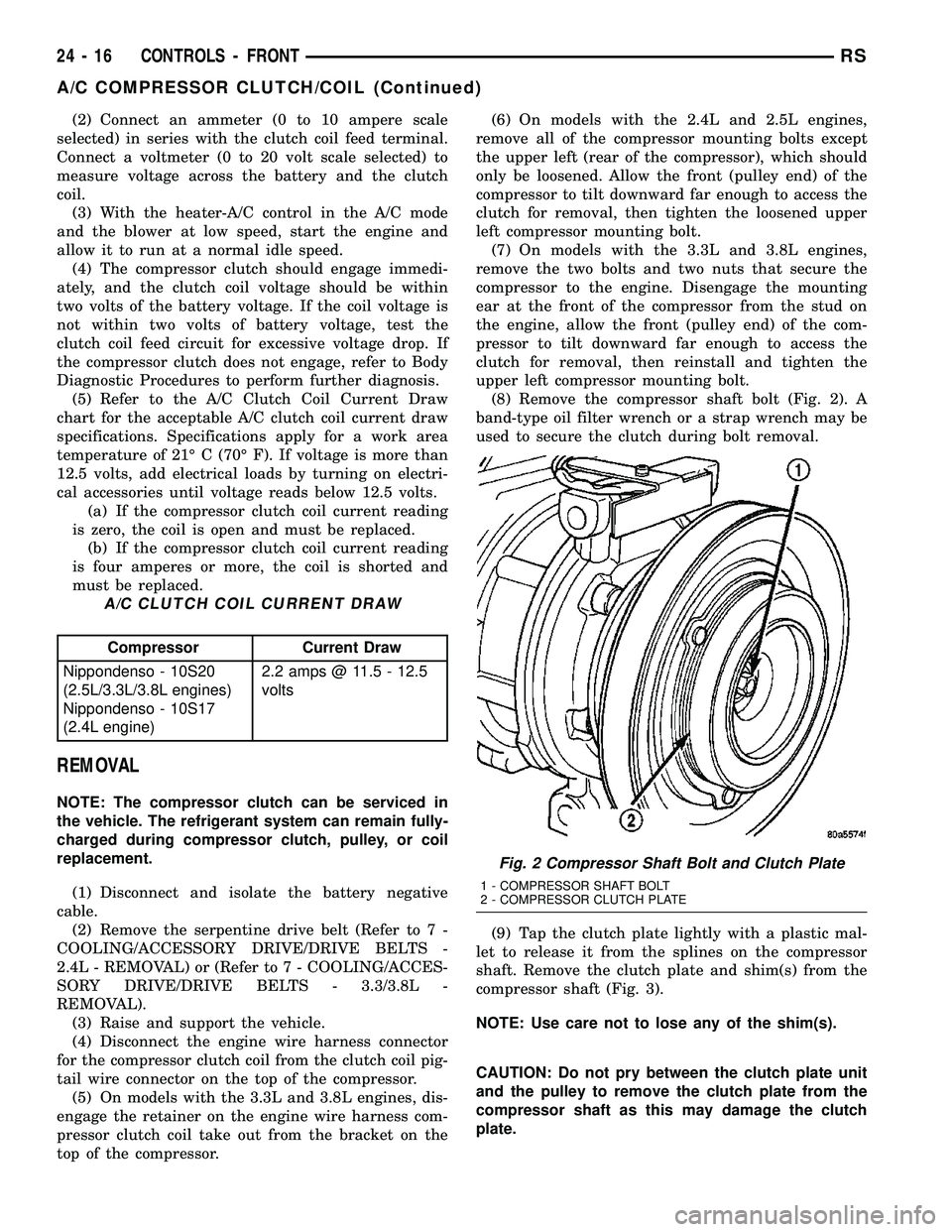
(8) Remove the compressor shaft bolt (Fig. 2). A
band-type oil filter wrench or a strap wrench may be
used to secure the clutch during bolt removal.
(9) Tap the clutch plate lightly with a plastic mal-
let to release it from the splines on the compressor
shaft. Remove the clutch plate and shim(s) from the
compressor shaft (Fig. 3).
NOTE: Use care not to lose any of the shim(s).
CAUTION: Do not pry between the clutch plate unit
and the pulley to remove the clutch plate from the
compressor shaft as this may damage the clutch
plate.
Fig. 2 Compressor Shaft Bolt and Clutch Plate
1 - COMPRESSOR SHAFT BOLT
2 - COMPRESSOR CLUTCH PLATE
24 - 16 CONTROLS - FRONTRS
A/C COMPRESSOR CLUTCH/COIL (Continued)
Page 2414 of 2585
COOLING/ACCESSORY DRIVE/DRIVE BELTS -
3.3L/3.8L - INSTALLATION).
(15) Lower the vehicle.
(16) Reconnect the battery negative cable.
CLUTCH BREAK-IN
After a new compressor clutch has been installed,
cycle the compressor clutch approximately twenty
times (five seconds on, then five seconds off). During
this procedure, set the A/C-heater control to the A/C
Recirculation Mode, the blower motor switch in the
highest speed position, and the engine speed at 1500
to 2000 rpm. This procedure (burnishing) will seat
the opposing friction surfaces and provide a higher
compressor clutch torque capability.
A/C COMPRESSOR CLUTCH
RELAY
DESCRIPTION
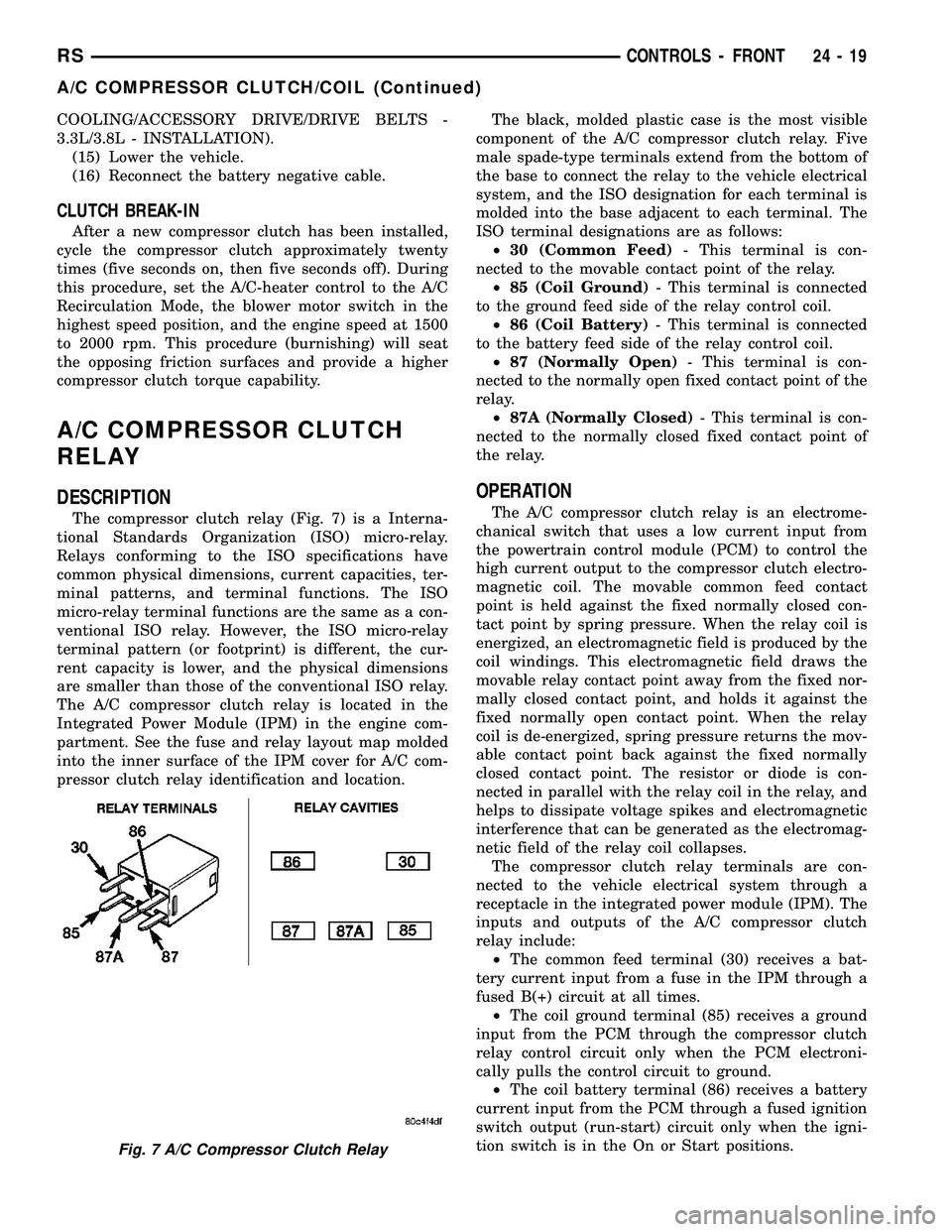
The compressor clutch relay (Fig. 7) is a Interna-
tional Standards Organization (ISO) micro-relay.
Relays conforming to the ISO specifications have
common physical dimensions, current capacities, ter-
minal patterns, and terminal functions. The ISO
micro-relay terminal functions are the same as a con-
ventional ISO relay. However, the ISO micro-relay
terminal pattern (or footprint) is different, the cur-
rent capacity is lower, and the physical dimensions
are smaller than those of the conventional ISO relay.
The A/C compressor clutch relay is located in the
Integrated Power Module (IPM) in the engine com-
partment. See the fuse and relay layout map molded
into the inner surface of the IPM cover for A/C com-
pressor clutch relay identification and location.The black, molded plastic case is the most visible
component of the A/C compressor clutch relay. Five
male spade-type terminals extend from the bottom of
the base to connect the relay to the vehicle electrical
system, and the ISO designation for each terminal is
molded into the base adjacent to each terminal. The
ISO terminal designations are as follows:
²30 (Common Feed)- This terminal is con-
nected to the movable contact point of the relay.
²85 (Coil Ground)- This terminal is connected
to the ground feed side of the relay control coil.
²86 (Coil Battery)- This terminal is connected
to the battery feed side of the relay control coil.
²87 (Normally Open)- This terminal is con-
nected to the normally open fixed contact point of the
relay.
²87A (Normally Closed)- This terminal is con-
nected to the normally closed fixed contact point of
the relay.
OPERATION
The A/C compressor clutch relay is an electrome-
chanical switch that uses a low current input from
the powertrain control module (PCM) to control the
high current output to the compressor clutch electro-
magnetic coil. The movable common feed contact
point is held against the fixed normally closed con-
tact point by spring pressure. When the relay coil is
energized, an electromagnetic field is produced by the
coil windings. This electromagnetic field draws the
movable relay contact point away from the fixed nor-
mally closed contact point, and holds it against the
fixed normally open contact point. When the relay
coil is de-energized, spring pressure returns the mov-
able contact point back against the fixed normally
closed contact point. The resistor or diode is con-
nected in parallel with the relay coil in the relay, and
helps to dissipate voltage spikes and electromagnetic
interference that can be generated as the electromag-
netic field of the relay coil collapses.
The compressor clutch relay terminals are con-
nected to the vehicle electrical system through a
receptacle in the integrated power module (IPM). The
inputs and outputs of the A/C compressor clutch
relay include:
²The common feed terminal (30) receives a bat-
tery current input from a fuse in the IPM through a
fused B(+) circuit at all times.
²The coil ground terminal (85) receives a ground
input from the PCM through the compressor clutch
relay control circuit only when the PCM electroni-
cally pulls the control circuit to ground.
²The coil battery terminal (86) receives a battery
current input from the PCM through a fused ignition
switch output (run-start) circuit only when the igni-
tion switch is in the On or Start positions.
Fig. 7 A/C Compressor Clutch Relay
RSCONTROLS - FRONT24-19
A/C COMPRESSOR CLUTCH/COIL (Continued)