2004 CHRYSLER VOYAGER check engine light
[x] Cancel search: check engine lightPage 1509 of 2585
FUEL DELIVERY
DESCRIPTION
The front wheel drive car uses a plastic fuel tank
located rear center of the vehicle.
The Fuel Delivery System consists of: the following
items:
²Electric fuel pump module
²Fuel filter
²Tubes/lines/hoses
²Fuel injectors
The in-tank fuel pump module contains the fuel
pump. The pump is serviced as part of the fuel pump
module. Refer to Fuel Pump Module.
The fuel filter is replaceable only as part of the
fuel pump module.
OPERATION
The fuel system provides fuel pressure by an
in-tank pump module. The Powertrain Control Mod-
ule (PCM) controls the operation of the fuel system
by providing battery voltage to the fuel pump
through the fuel pump relay. The PCM requires only
three inputs and a good ground to operate the fuel
pump relay. The three inputs are:
²Ignition voltage
²Crankshaft Position (CKP) sensor
²Camshaft Position (CMP) sensor
DIAGNOSIS AND TESTING - FUEL DELIVERY
SYSTEM
(Refer to Appropriate Diagnostic Information)
STANDARD PROCEDURE
STANDARD PROCEDURE - FUEL SYSTEM
PRESSURE RELEASE PROCEDURE
(1) Remove Fuel Pump relay from Power Distribu-
tion Center (PDC). For location of relay, refer to label
on underside of PDC cover.
(2) Start and run engine until it stalls.
(3) Attempt restarting engine until it will no
longer run.
(4) Turn ignition key to OFF position.
(5) Return fuel pump relay to PDC.
(6) One or more Diagnostic Trouble Codes (DTC's)
may have been stored in PCM memory due to fuel
pump relay removal. The DRB IIItscan tool must be
used to erase a DTC.
STANDARD PROCEDURE - DRAINING FUEL
TANK
Two different procedures may be used to drain fuel
tank (lowering tank or using DRBIIItscan tool).The quickest draining procedure involves lowering
the fuel tank.
WARNING: RELEASE FUEL SYSTEM PRESSURE
BEFORE SERVICING FUEL SYSTEM COMPONENTS.
SERVICE VEHICLES IN WELL VENTILATED AREAS
AND AVOID IGNITION SOURCES. NEVER SMOKE
WHILE SERVICING THE VEHICLE. THIS MAY
RESULT IN PERSONAL INJURY OR DEATH.
As an alternative procedure, the electric fuel pump
may be activated allowing tank to be drained at fuel
rail connection. Refer to DRBIIItscan tool for fuel
pump activation procedures. Before disconnecting
fuel line at fuel rail, release fuel pressure. Refer to
the Fuel System Pressure Release Procedure in this
group for procedures. Disconnect the fuel line at the
fuel rail and remove the plastic retainer from the
fuel rail. Take plastic retainer and install it back into
the fuel line from body. Check the O-ring and make
sure that it is in place and not damaged. Attach end
of special test hose tool number 6539 at fuel line con-
nection from the body line. Position opposite end of
this hose tool to an approved gasoline draining sta-
tion. Activate fuel pump and drain tank until empty.
When done remove the special test hose tool number
6539 from the body line. Remove the plastic retainer
from the special test hose tool number 6539 and rein-
stall it into the fuel line from the body. Check the
O-ring and make sure that it is in place and not
damaged. Install the fuel line to the fuel rail.
If electric fuel pump is not operating, tank must be
lowered for fuel draining. Refer to following proce-
dures.
(1) Remove fuel filler cap.
(2) Perform the Fuel System Pressure Release pro-
cedure.
(3) Disconnect negative cable from battery.
(4) Raise vehicle and support.
(5) Certain models are equipped with a separate
grounding wire (strap) connecting the fuel fill tube
assembly to the body. Disconnect wire by removing
screw.
(6) Open fuel fill door and remove screws mount-
ing fuel filler tube assembly to body. Do not discon-
nect rubber fuel fill or vent hoses from tank at this
time.
(7) Place a transmission jack under center of fuel
tank. Apply a slight amount of pressure to fuel tank
with transmission jack.
(8) Remove fuel tank mounting straps.
(9)Lower the tank just enough so that the
filler tube fitting is the highest point of the fuel
tank.
(10) Remove filler tube from fuel tank. Tank will
be drained through this fitting.
14 - 2 FUEL DELIVERYRS
Page 1518 of 2585
OPERATION
All models pass a full 360 degree rollover test
without fuel leakage. To accomplish this, fuel and
vapor flow controls are required for all fuel tank con-
nections.
All models are equipped with either one or two
check valves mounted into the top of the fuel tank (or
pump module).
An evaporation control system is connected to the
check valve(s)/control valve(Refer to 25 - EMIS-
SIONS CONTROL/EVAPORATIVE EMISSIONS/
ORVR - OPERATION) to reduce emissions of fuel
vapors into the atmosphere, when the tank is vented
due to vapor expansion in the tank. When fuel evap-
orates from the fuel tank, vapors pass through vent
hoses or tubes to a charcoal canister where they are
temporarily held. When the engine is running, the
vapors are drawn into the intake manifold. In addi-
tion, fuel vapors produced during vehicle refueling
are allowed to pass through the vent hoses/tubes to
the charcoal canister(s) for temporary storage (prior
to being drawn into the intake manifold). All models
are equipped with a self-diagnosing system using a
Leak Detection Pump (LDP) or Natural Vacuum
Leak Detection (NVLD). Refer to the Emission Con-
trol System for additional information.
INLET CHECK VALVE
All vehicles have an inlet check valve on the inside
of the fuel tank at the filler inlet
The valve prevents fuel from splashing back on
customer during vehicle refueling. The valve is a
non-serviceable item.
REMOVAL
(1) Remove fuel filler cap and perform Fuel Sys-
tem Pressure Release procedure (Fig. 14).
(2) Disconnect negative cable from battery.
(3) Insert fuel siphon hose into fuel filler neck and
push it into the tank.
(4) Drain fuel tank dry into holding tank or a
properly labeledGASOLINEsafety container.
(5) Raise vehicle on hoist and support.
(6) Use a transmission jack to support fuel tank.
Remove bolts from fuel tank straps.
(7) Lower tank slightly.
(8) Disconnect the fuel filler vent tube. Squeeze
tabs and pull apart (Fig. 15).
(9) Disconnect the fuel fill hose at the fuel tank
filler metal tubeNOT AT THE FUEL TANK(Fig.
15).
(10) Disconnect fuel line and vapor line at the
front of the fuel tank.
The fuel pump module electrical connector
has a retainer that locks it in place.(11) Slide fuel pump module electrical connector
lock to unlock.
(12) Push down on connector retainer (Fig. 16) and
pull connector off module.
(13) Lower tank from vehicle. Remove fuel filler
vent tube from frame (Fig. 17).
Fig. 14 Fuel Tank
1 - ROLLOVER VALVE
2 - FUEL FILLER INLET
3 - ROLLOVER VALVE
4 - FUEL PUMP MODULE
Fig. 15 FUEL FILLER AND VENT TUBE
1 - Filler Tube
2 - Vent Tube
RSFUEL DELIVERY14-11
FUEL TANK (Continued)
Page 1519 of 2585

INSTALLATION
(1) Position fuel tank on transmission jack. Con-
nect check valve hose. Connect fuel filler tube vent
hose to fuel filler tube.
(2) Feed filler vent line thru frame rail.
(3) Raise tank into position and carefully work fuel
filler metal tube into the rubber hose on fuel tank. A
light coating of clean engine oil on the tube end may
be used to aid assembly.
(4) Tighten strap bolts to 54 N´m (40 ft. lbs.)
torque. Tighten T strap bolt to 28.2 N´m (250 in.
lbs.). Remove transmission jack.
(5) Tighten filler hose clamp to 3.3 N´m (30 in.
lbs.).CAUTION: Ensure straps are not twisted or bent
before or after tightening strap screws.
(6) Connect fuel pump/module electrical connector.
Place retainer in locked position.
(7) Lubricate the fuel supply line with clean 30
weight engine oil, install the quick connect fuel fit-
ting. Refer to Tube/Fitting Assembly in the Fuel
Delivery section of this section.
(8) Connect the control vapor lines at front of
tank.
(9) Pull-pull-push on all connections to make sure
of connection.
(10) Fill fuel tank, replace cap, and connect bat-
tery negative cable.
(11) Use the DRBIIItscan tool to pressurize the
fuel system. Check for leaks.
FUEL TANK FILLER TUBE
REMOVAL
(1) Disconnect the negative battery cable.
(2) Remove the 3 screws at the filler door.
(3) Raise and support vehicle
(4) Remove the left rear tire.
(5) Remove the splash shield (Fig. 19) or (Fig. 18).
(6)For RGRemove the canister from filler tube
(Fig. 20).
(7)For RGDisconnect the vent at the top of the
filler tube.
(8) Remove the ground strap.
(9) Remove filler tube at tank.
Fig. 16 Pump Module Connector Retainer and Lock
1 - PUSH DOWN ON RETAINER
2 - CONNECTOR LOCK
Fig. 17 VENT HOSE
Fig. 18 FUEL FILLER TUBE (RS)
14 - 12 FUEL DELIVERYRS
FUEL TANK (Continued)
Page 1526 of 2585
1 second. Therefore, battery voltage is not supplied to
the fuel pump, ignition coil, fuel injectors and heated
oxygen sensors.
ENGINE START-UP MODE
This is an OPEN LOOP mode. If the vehicle is in
park or neutral (automatic transaxles) or the clutch
pedal is depressed (manual transaxles) the ignition
switch energizes the starter relay when the engine is
not running. The following actions occur when the
starter motor is engaged.
²If the PCM receives the camshaft position sensor
and crankshaft position sensor signals, it energizes
the Auto Shutdown (ASD) relay and fuel pump relay.
If the PCM does not receive both signals within
approximately one second, it will not energize the
ASD relay and fuel pump relay. The ASD and fuel
pump relays supply battery voltage to the fuel pump,
fuel injectors, ignition coil, (EGR solenoid and PCV
heater if equipped) and heated oxygen sensors.
²The PCM energizes the injectors (on the 69É
degree falling edge) for a calculated pulse width until
it determines crankshaft position from the camshaft
position sensor and crankshaft position sensor sig-
nals. The PCM determines crankshaft position within
1 engine revolution.
²After determining crankshaft position, the PCM
begins energizing the injectors in sequence. It adjusts
injector pulse width and controls injector synchroni-
zation by turning the individual ground paths to the
injectors On and Off.
²When the engine idles within 64 RPM of its
target RPM, the PCM compares current MAP sensor
value with the atmospheric pressure value received
during the Ignition Switch On (zero RPM) mode.
Once the ASD and fuel pump relays have been
energized, the PCM determines injector pulse width
based on the following:
²MAP
²Engine RPM
²Battery voltage
²Engine coolant temperature
²Inlet/Intake air temperature (IAT)
²Throttle position
²The number of engine revolutions since cranking
was initiated
During Start-up the PCM maintains ignition tim-
ing at 9É BTDC.
ENGINE WARM-UP MODE
This is an OPEN LOOP mode. The following inputs
are received by the PCM:
²Manifold Absolute Pressure (MAP)
²Crankshaft position (engine speed)
²Engine coolant temperature
²Inlet/Intake air temperature (IAT)²Camshaft position
²Knock sensor
²Throttle position
²A/C switch status
²Battery voltage
²Vehicle speed
²Speed control
²O2 sensors
The PCM adjusts injector pulse width and controls
injector synchronization by turning the individual
ground paths to the injectors On and Off.
The PCM adjusts ignition timing and engine idle
speed. Engine idle speed is adjusted through the idle
air control motor.
CRUISE OR IDLE MODE
When the engine is at operating temperature this
is a CLOSED LOOP mode. During cruising or idle
the following inputs are received by the PCM:
²Manifold absolute pressure
²Crankshaft position (engine speed)
²Inlet/Intake air temperature
²Engine coolant temperature
²Camshaft position
²Knock sensor
²Throttle position
²Exhaust gas oxygen content (O2 sensors)
²A/C switch status
²Battery voltage
²Vehicle speed
The PCM adjusts injector pulse width and controls
injector synchronization by turning the individual
ground paths to the injectors On and Off.
The PCM adjusts engine idle speed and ignition
timing. The PCM adjusts the air/fuel ratio according
to the oxygen content in the exhaust gas (measured
by the upstream and downstream heated oxygen sen-
sor).
The PCM monitors for engine misfire. During
active misfire and depending on the severity, the
PCM either continuously illuminates or flashes the
malfunction indicator lamp (Check Engine light on
instrument panel). Also, the PCM stores an engine
misfire DTC in memory, if 2nd trip with fault.
The PCM performs several diagnostic routines.
They include:
²Oxygen sensor monitor
²Downstream heated oxygen sensor diagnostics
during open loop operation (except for shorted)
²Fuel system monitor
²EGR monitor (if equipped)
²Purge system monitor
²Catalyst efficiency monitor
²All inputs monitored for proper voltage range,
rationality.
RSFUEL INJECTION14-19
FUEL INJECTION (Continued)
Page 1582 of 2585
OPERATION
The power steering pump is a constant displace-
ment vane type pump. The 2.4L pump has an inte-
gral fluid reservoir and there is a secondary remote
non-flow reservoir which acts only as a fluid fill and
check point. The 3.3L/3.8L pump houses very little
fluid and is therefore supplied by a remote flow
through reservoir.
WARNING
WARNING: POWER STEERING FLUID, ENGINE
PARTS AND EXHAUST SYSTEM MAY BE
EXTREMELY HOT IF ENGINE HAS BEEN RUNNING.DO NOT START ENGINE WITH ANY LOOSE OR DIS-
CONNECTED HOSES. DO NOT ALLOW HOSES TO
TOUCH HOT EXHAUST MANIFOLD OR CATALYST.
WARNING: FLUID LEVEL SHOULD BE CHECKED
WITH THE ENGINE OFF TO PREVENT PERSONAL
INJURY FROM MOVING PARTS.
CAUTION
CAUTION: When the system is open, cap all open
ends of the hoses, power steering pump fittings or
power steering gear ports to prevent entry of for-
eign material into the components.
STANDARD PROCEDURE - POWER STEERING
PUMP INITIAL OPERATION
WARNING: FLUID LEVEL SHOULD BE CHECKED
AND ADJUSTED WITH ENGINE OFF TO PREVENT
INJURY FROM MOVING ENGINE COMPONENTS.
CAUTION: Use only MoparTAutomatic Transmis-
sion Fluid (MS-9602) in power steering system. Use
of other MoparTpower steering fluids (MS5931 and
MS9933) should be avoided to ensure peak perfor-
mance of the power steering system under all oper-
ating conditions. Do not overfill.
Read the fluid level through the side of the power
steering fluid reservoir. The fluid level should indi-
cateªFILL RANGEºwhen the fluid is at a temper-
ature of approximately 21ÉC to 27ÉC (70ÉF to 80ÉF).
(1) Wipe the filler cap and area clean, then remove
the cap.
(2) Fill the fluid reservoir to the proper level and
let the fluid settle for at least two (2) minutes.
(3) Start the engine and let run for a few seconds,
then turn the engine off.
(4) Add fluid if necessary. Repeat the above steps
until the fluid level remains constant after running
the engine.
(5) Raise the front wheels off the ground.
(6) Start the engine.
(7) Slowly turn the steering wheel right and left,
lightly contacting the wheel stops.
(8) Add fluid if necessary.
(9) Lower the vehicle, then turn the steering wheel
slowly from lock-to-lock.
(10) Stop the engine. Check the fluid level and
refill as required.
(11) If the fluid is extremely foamy, allow the vehi-
cle to stabilize a few minutes, then repeat the above
procedure.
Fig. 1 POWER STEERING PUMP (2.4L)
1 - PULLEY
2 - BRACKET
3 - PRESSURE FITTING
4 - RETURN FITTING
5 - SUPPLY FITTING
Fig. 2 POWER STEERING PUMP (3.3L/3.8L)
1 - SUPPLY FITTING
2 - PRESSURE FITTING
3 - PULLEY
RSPUMP19-37
PUMP (Continued)
Page 1716 of 2585
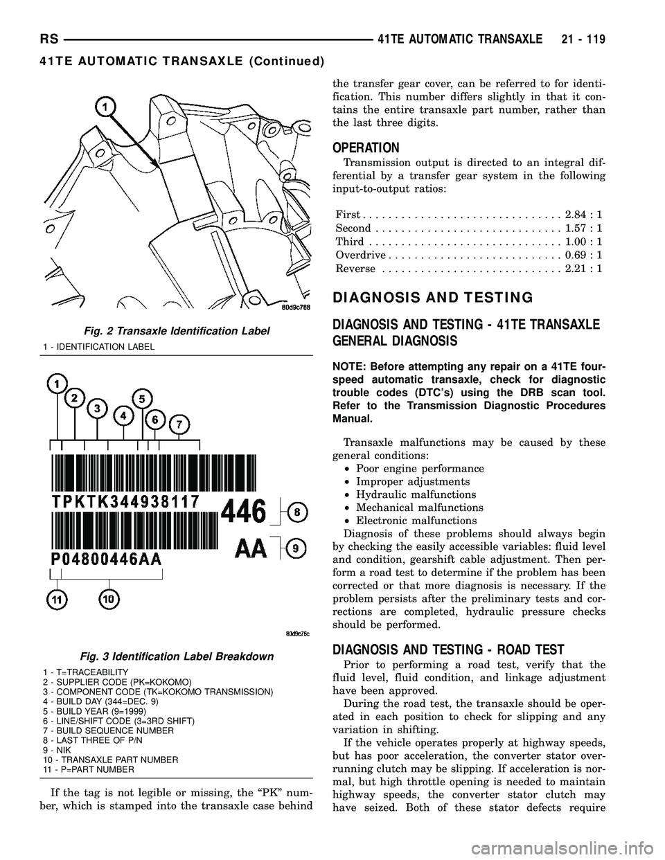
If the tag is not legible or missing, the ªPKº num-
ber, which is stamped into the transaxle case behindthe transfer gear cover, can be referred to for identi-
fication. This number differs slightly in that it con-
tains the entire transaxle part number, rather than
the last three digits.
OPERATION
Transmission output is directed to an integral dif-
ferential by a transfer gear system in the following
input-to-output ratios:
First...............................2.84 : 1
Second.............................1.57 : 1
Third..............................1.00 : 1
Overdrive...........................0.69 : 1
Reverse............................2.21 : 1
DIAGNOSIS AND TESTING
DIAGNOSIS AND TESTING - 41TE TRANSAXLE
GENERAL DIAGNOSIS
NOTE: Before attempting any repair on a 41TE four-
speed automatic transaxle, check for diagnostic
trouble codes (DTC's) using the DRB scan tool.
Refer to the Transmission Diagnostic Procedures
Manual.
Transaxle malfunctions may be caused by these
general conditions:
²Poor engine performance
²Improper adjustments
²Hydraulic malfunctions
²Mechanical malfunctions
²Electronic malfunctions
Diagnosis of these problems should always begin
by checking the easily accessible variables: fluid level
and condition, gearshift cable adjustment. Then per-
form a road test to determine if the problem has been
corrected or that more diagnosis is necessary. If the
problem persists after the preliminary tests and cor-
rections are completed, hydraulic pressure checks
should be performed.
DIAGNOSIS AND TESTING - ROAD TEST
Prior to performing a road test, verify that the
fluid level, fluid condition, and linkage adjustment
have been approved.
During the road test, the transaxle should be oper-
ated in each position to check for slipping and any
variation in shifting.
If the vehicle operates properly at highway speeds,
but has poor acceleration, the converter stator over-
running clutch may be slipping. If acceleration is nor-
mal, but high throttle opening is needed to maintain
highway speeds, the converter stator clutch may
have seized. Both of these stator defects require
Fig. 2 Transaxle Identification Label
1 - IDENTIFICATION LABEL
Fig. 3 Identification Label Breakdown
1 - T=TRACEABILITY
2 - SUPPLIER CODE (PK=KOKOMO)
3 - COMPONENT CODE (TK=KOKOMO TRANSMISSION)
4 - BUILD DAY (344=DEC. 9)
5 - BUILD YEAR (9=1999)
6 - LINE/SHIFT CODE (3=3RD SHIFT)
7 - BUILD SEQUENCE NUMBER
8 - LAST THREE OF P/N
9 - NIK
10 - TRANSAXLE PART NUMBER
11 - P=PART NUMBER
RS41TE AUTOMATIC TRANSAXLE21 - 119
41TE AUTOMATIC TRANSAXLE (Continued)
Page 1844 of 2585
TORQUE CONVERTER CLUTCH (TCC)
In a standard torque converter, the impeller and
turbine are rotating at about the same speed and the
stator is freewheeling, providing no torque multipli-
cation. By applying the turbine's piston to the front
cover's friction material, a total converter engage-
ment can be obtained. The result of this engagement
is a direct 1:1 mechanical link between the engine
and the transmission.
The engagement and disengagement of the TCC
are automatic and controlled by the Powertrain Con-
trol Module (PCM). The engagement cannot be acti-
vated in the lower gears because it eliminates the
torque multiplication effect of the torque converter
necessary for acceleration. Inputs that determine
clutch engagement are: coolant temperature, vehicle
speed and throttle position. The torque converter
clutch is engaged by the clutch solenoid on the valve
body. The clutch will engage at approximately 56
km/h (35 mph) with light throttle, after the shift to
third gear.
REMOVAL
(1) Remove transmission and torque converter
from vehicle. (Refer to 21 - TRANSMISSION/TRANS-
AXLE/AUTOMATIC - 41TE - REMOVAL)
(2) Place a suitable drain pan under the converter
housing end of the transmission.
CAUTION: Verify that transmission is secure on the
lifting device or work surface, the center of gravity
of the transmission will shift when the torque con-
verter is removed creating an unstable condition.
The torque converter is a heavy unit. Use caution
when separating the torque converter from the
transmission.
(3) Pull the torque converter forward until the cen-
ter hub clears the oil pump seal.
(4) Separate the torque converter from the trans-
mission.
INSTALLATION
Check converter hub and drive notches for sharp
edges, burrs, scratches, or nicks. Polish the hub and
notches with 320/400 grit paper or crocus cloth if nec-
essary. The hub must be smooth to avoid damaging
the pump seal at installation.
(1) Lubricate converter hub and oil pump seal lip
with transmission fluid.
(2) Place torque converter in position on transmis-
sion.
CAUTION: Do not damage oil pump seal or bushing
while inserting torque converter into the front of the
transmission.(3) Align torque converter to oil pump seal open-
ing.
(4) Insert torque converter hub into oil pump.
(5) While pushing torque converter inward, rotate
converter until converter is fully seated in the oil
pump gears.
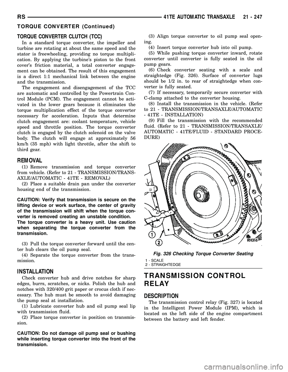
(6) Check converter seating with a scale and
straightedge (Fig. 326). Surface of converter lugs
should be 1/2 in. to rear of straightedge when con-
verter is fully seated.
(7) If necessary, temporarily secure converter with
C-clamp attached to the converter housing.
(8) Install the transmission in the vehicle. (Refer
to 21 - TRANSMISSION/TRANSAXLE/AUTOMATIC
- 41TE - INSTALLATION)
(9) Fill the transmission with the recommended
fluid. (Refer to 21 - TRANSMISSION/TRANSAXLE/
AUTOMATIC - 41TE/FLUID - STANDARD PROCE-
DURE)TRANSMISSION CONTROL
RELAY
DESCRIPTION
The transmission control relay (Fig. 327) is located
in the Intelligent Power Module (IPM), which is
located on the left side of the engine compartment
between the battery and left fender.
Fig. 326 Checking Torque Converter Seating
1 - SCALE
2 - STRAIGHTEDGE
RS41TE AUTOMATIC TRANSAXLE21 - 247
TORQUE CONVERTER (Continued)
Page 1965 of 2585

STANDARD PROCEDURE - FLUID AND FILTER
SERVICE
NOTE: Refer to the maintenance schedules in
LUBRICATION and MAINTENANCE, or the vehicle
owner's manual, for the recommended maintenance
(fluid/filter change) intervals for this transaxle.
NOTE: Only fluids of the type labeled MoparTATF+4
should be used. A filter change should be made at
the time of the transmission oil change. The magnet
(on the inside of the oil pan) should also be cleaned
with a clean, dry cloth.
NOTE: If the transaxle is disassembled for any rea-
son, the fluid and filter should be changed.
FLUID/FILTER SERVICE (RECOMMENDED)
(1) Raise vehicle on a hoist. Refer to LUBRICA-
TION and MAINTENANCE for proper procedures.
Place a drain container with a large opening, under
transaxle oil pan. (2) Remove both engine mount-to-engine cross-
member cradle nuts. Using suitable screw jack and
wood block, raise engine and transmission slightly to
facilitate transaxle oil pan removal and installation. (3) Loosen pan bolts and tap the pan at one corner
to break it loose allowing fluid to drain, then remove
the oil pan. (4) Install a new filter and o-ring on bottom of the
valve body (Fig. 189). (5) Clean the oil pan and magnet. Reinstall pan
using new Mopar Silicone Adhesive sealant. Tighten
oil pan bolts to 19 N´m (165 in. lbs.). (6) Pour four quarts of Mopar tATF+4 through the
dipstick opening. (7) Start engine and allow to idle for at least one
minute. Then, with parking and service brakes
applied, move selector lever momentarily to each
position, ending in the park or neutral position. (8) Check the transaxle fluid level and add an
appropriate amount to bring the transaxle fluid level
to 3mm (1/8 in.) below the lowest mark on the dip-
stick (Fig. 190).
(9) Recheck the fluid level after the transaxle has
reached normal operating temperature (180ÉF.). Refer
to Fluid Level and Condition Check for the proper
fluid fill procedure. (10) To prevent dirt from entering transaxle, make
certain that dipstick is fully seated into the dipstick
opening.
DIPSTICK TUBE FLUID SUCTION METHOD
(ALTERNATIVE)
(1) When performing the fluid suction method,
make sure the transaxle is at full operating temper-
ature. (2) To perform the dipstick tube fluid suction
method, use a suitable fluid suction device (VaculaŸ
or equivalent). (3) Insert the fluid suction line into the dipstick
tube.
NOTE: Verify that the suction line is inserted to the
lowest point of the transaxle oil pan. This will
ensure complete evacuation of the fluid in the pan.
(4) Follow the manufacturers recommended proce-
dure and evacuate the fluid from the transaxle.
Fig. 189 Filter and O-Ring
1 - OIL FILTER
2 - O-RING
Fig. 190 Fluid Level Indicator
1 - FLUID LEVEL INDICATOR
21s - 104 40TE AUTOMATIC TRANSAXLERS
FLUID (Continued)