Page 2027 of 2585
41TE AUTOMATIC TRANSAXLE
TABLE OF CONTENTS
page page
41TE AUTOMATIC TRANSAXLE DISASSEMBLY ........................166
ASSEMBLY ...........................184
ACCUMULATOR DESCRIPTION ........................206 VALVE BODY
REMOVAL ............................206
DISASSEMBLY ........................208
ASSEMBLY ...........................212
INSTALLATION ........................217
41TE AUTOMATIC
TRANSAXLE
DISASSEMBLY
NOTE: If transaxle is being overhauled (clutch and/or
seal replacement) or replaced, it is necessary to per-
form the PCM/TCM Quick Learn Procedure. (Refer to 8 -
ELECTRICAL/ELECTRONIC CONTROL MODULES/POW-
ERTRAIN/TRANSMISSION CONTROL MODULE - STAN-
DARD PROCEDURE)
NOTE: This procedure does not include final drive
(differential) disassembly.
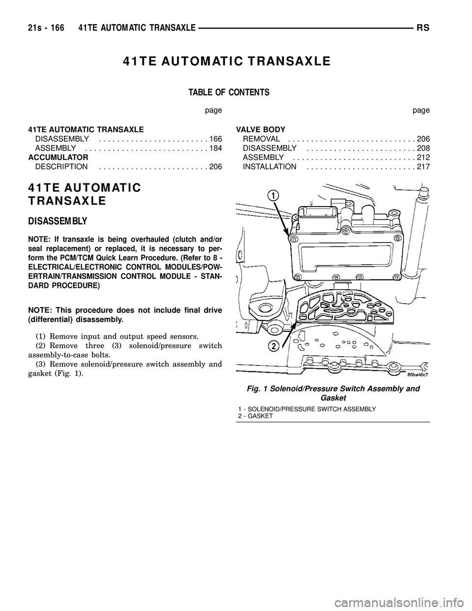
(1) Remove input and output speed sensors.
(2) Remove three (3) solenoid/pressure switch
assembly-to-case bolts. (3) Remove solenoid/pressure switch assembly and
gasket (Fig. 1).
Fig. 1 Solenoid/Pressure Switch Assembly and Gasket
1 - SOLENOID/PRESSURE SWITCH ASSEMBLY
2 - GASKET
21s - 166 41TE AUTOMATIC TRANSAXLERS
Page 2032 of 2585
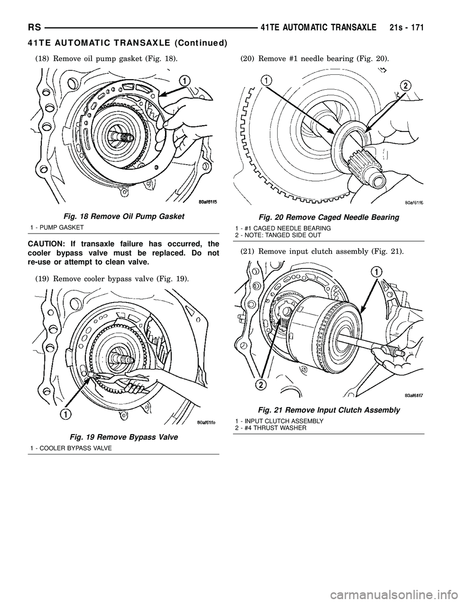
(18) Remove oil pump gasket (Fig. 18).
CAUTION: If transaxle failure has occurred, the
cooler bypass valve must be replaced. Do not
re-use or attempt to clean valve. (19) Remove cooler bypass valve (Fig. 19). (20) Remove #1 needle bearing (Fig. 20).
(21) Remove input clutch assembly (Fig. 21).
Fig. 18 Remove Oil Pump Gasket
1 - PUMP GASKET
Fig. 19 Remove Bypass Valve
1 - COOLER BYPASS VALVE
Fig. 20 Remove Caged Needle Bearing
1 - #1 CAGED NEEDLE BEARING
2 - NOTE: TANGED SIDE OUT
Fig. 21 Remove Input Clutch Assembly
1 - INPUT CLUTCH ASSEMBLY
2 - #4 THRUST WASHER
RS
41TE AUTOMATIC TRANSAXLE21s - 171
41TE AUTOMATIC TRANSAXLE (Continued)
Page 2034 of 2585
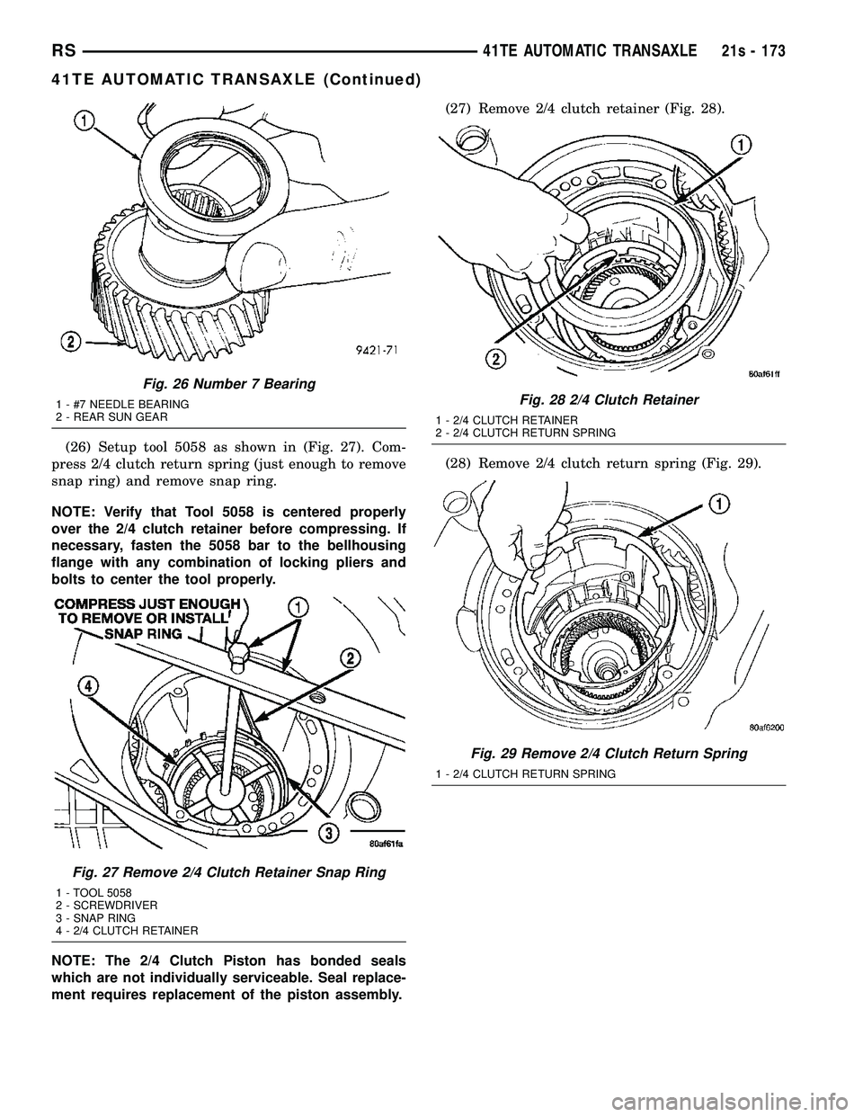
(26) Setup tool 5058 as shown in (Fig. 27). Com-
press 2/4 clutch return spring (just enough to remove
snap ring) and remove snap ring.
NOTE: Verify that Tool 5058 is centered properly
over the 2/4 clutch retainer before compressing. If
necessary, fasten the 5058 bar to the bellhousing
flange with any combination of locking pliers and
bolts to center the tool properly.
NOTE: The 2/4 Clutch Piston has bonded seals
which are not individually serviceable. Seal replace-
ment requires replacement of the piston assembly. (27) Remove 2/4 clutch retainer (Fig. 28).
(28) Remove 2/4 clutch return spring (Fig. 29).
Fig. 26 Number 7 Bearing
1 - #7 NEEDLE BEARING
2 - REAR SUN GEAR
Fig. 27 Remove 2/4 Clutch Retainer Snap Ring
1 - TOOL 5058
2 - SCREWDRIVER
3 - SNAP RING
4 - 2/4 CLUTCH RETAINER
Fig. 28 2/4 Clutch Retainer
1 - 2/4 CLUTCH RETAINER
2 - 2/4 CLUTCH RETURN SPRING
Fig. 29 Remove 2/4 Clutch Return Spring
1 - 2/4 CLUTCH RETURN SPRING
RS
41TE AUTOMATIC TRANSAXLE21s - 173
41TE AUTOMATIC TRANSAXLE (Continued)
Page 2035 of 2585
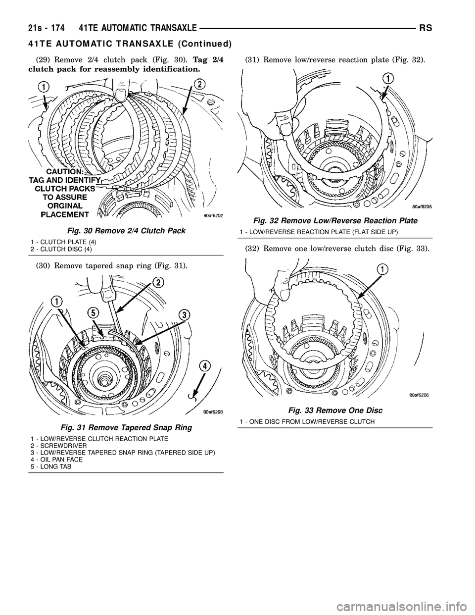
(29) Remove 2/4 clutch pack (Fig. 30).Tag 2/4
clutch pack for reassembly identification.
(30) Remove tapered snap ring (Fig. 31). (31) Remove low/reverse reaction plate (Fig. 32).
(32) Remove one low/reverse clutch disc (Fig. 33).
Fig. 30 Remove 2/4 Clutch Pack
1 - CLUTCH PLATE (4)
2 - CLUTCH DISC (4)
Fig. 31 Remove Tapered Snap Ring
1 - LOW/REVERSE CLUTCH REACTION PLATE
2 - SCREWDRIVER
3 - LOW/REVERSE TAPERED SNAP RING (TAPERED SIDE UP)
4 - OIL PAN FACE
5 - LONG TAB
Fig. 32 Remove Low/Reverse Reaction Plate
1 - LOW/REVERSE REACTION PLATE (FLAT SIDE UP)
Fig. 33 Remove One Disc
1 - ONE DISC FROM LOW/REVERSE CLUTCH
21s - 174 41TE AUTOMATIC TRANSAXLERS
41TE AUTOMATIC TRANSAXLE (Continued)
Page 2036 of 2585
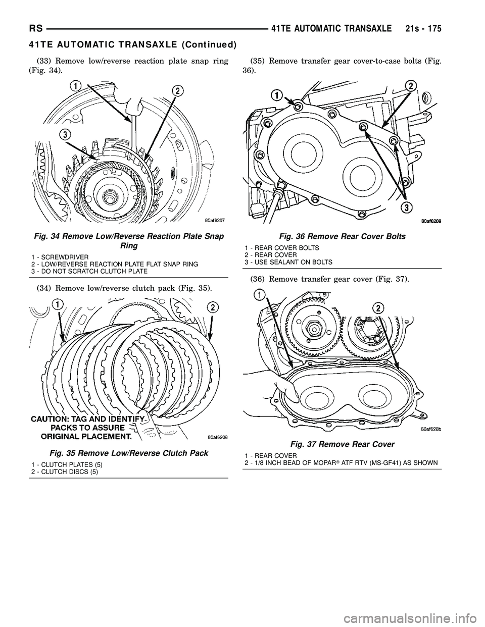
(33) Remove low/reverse reaction plate snap ring
(Fig. 34).
(34) Remove low/reverse clutch pack (Fig. 35). (35) Remove transfer gear cover-to-case bolts (Fig.
36).
(36) Remove transfer gear cover (Fig. 37).
Fig. 34 Remove Low/Reverse Reaction Plate Snap Ring
1 - SCREWDRIVER
2 - LOW/REVERSE REACTION PLATE FLAT SNAP RING
3 - DO NOT SCRATCH CLUTCH PLATE
Fig. 35 Remove Low/Reverse Clutch Pack
1 - CLUTCH PLATES (5)
2 - CLUTCH DISCS (5)
Fig. 36 Remove Rear Cover Bolts
1 - REAR COVER BOLTS
2 - REAR COVER
3 - USE SEALANT ON BOLTS
Fig. 37 Remove Rear Cover
1 - REAR COVER
2 - 1/8 INCH BEAD OF MOPAR TATF RTV (MS-GF41) AS SHOWN
RS 41TE AUTOMATIC TRANSAXLE21s - 175
41TE AUTOMATIC TRANSAXLE (Continued)
Page 2042 of 2585
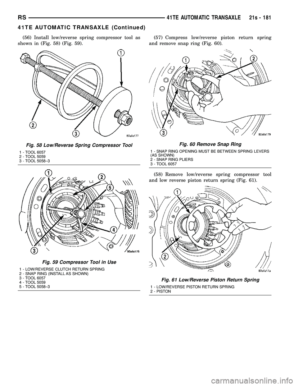
(56) Install low/reverse spring compressor tool as
shown in (Fig. 58) (Fig. 59). (57) Compress low/reverse piston return spring
and remove snap ring (Fig. 60).
(58) Remove low/reverse spring compressor tool
and low reverse piston return spring (Fig. 61).
Fig. 58 Low/Reverse Spring Compressor Tool
1 - TOOL 6057
2 - TOOL 5059
3 - TOOL 5058±3
Fig. 59 Compressor Tool in Use
1 - LOW/REVERSE CLUTCH RETURN SPRING
2 - SNAP RING (INSTALL AS SHOWN)
3 - TOOL 6057
4 - TOOL 5059
5 - TOOL 5058±3
Fig. 60 Remove Snap Ring
1 - SNAP RING OPENING MUST BE BETWEEN SPRING LEVERS
(AS SHOWN)
2 - SNAP RING PLIERS
3 - TOOL 6057
Fig. 61 Low/Reverse Piston Return Spring
1 - LOW/REVERSE PISTON RETURN SPRING
2 - PISTON
RS 41TE AUTOMATIC TRANSAXLE21s - 181
41TE AUTOMATIC TRANSAXLE (Continued)
Page 2043 of 2585
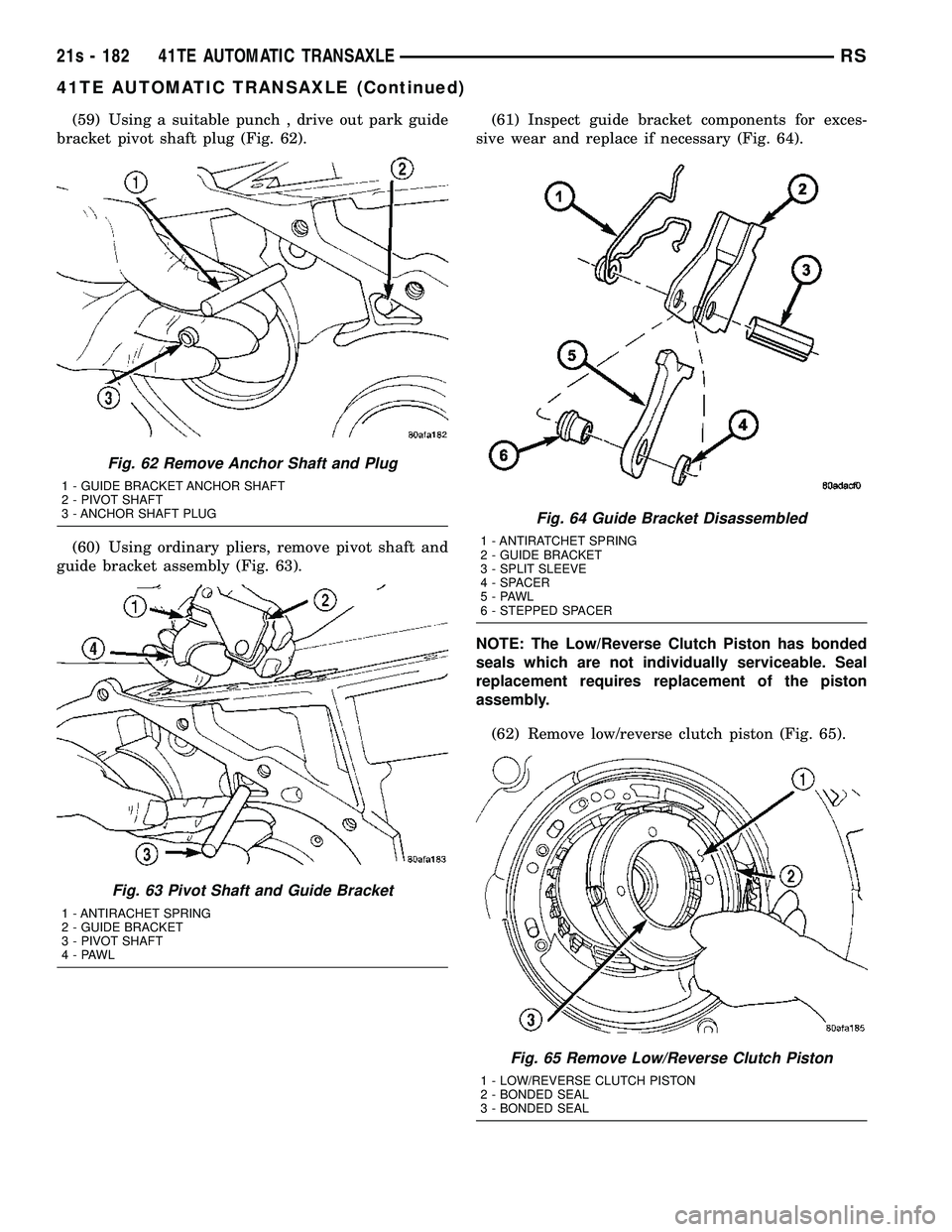
(59) Using a suitable punch , drive out park guide
bracket pivot shaft plug (Fig. 62).
(60) Using ordinary pliers, remove pivot shaft and
guide bracket assembly (Fig. 63). (61) Inspect guide bracket components for exces-
sive wear and replace if necessary (Fig. 64).
NOTE: The Low/Reverse Clutch Piston has bonded
seals which are not individually serviceable. Seal
replacement requires replacement of the piston
assembly.
(62) Remove low/reverse clutch piston (Fig. 65).
Fig. 62 Remove Anchor Shaft and Plug
1 - GUIDE BRACKET ANCHOR SHAFT
2 - PIVOT SHAFT
3 - ANCHOR SHAFT PLUG
Fig. 63 Pivot Shaft and Guide Bracket
1 - ANTIRACHET SPRING
2 - GUIDE BRACKET
3 - PIVOT SHAFT
4-PAWL
Fig. 64 Guide Bracket Disassembled
1 - ANTIRATCHET SPRING
2 - GUIDE BRACKET
3 - SPLIT SLEEVE
4 - SPACER
5-PAWL
6 - STEPPED SPACER
Fig. 65 Remove Low/Reverse Clutch Piston
1 - LOW/REVERSE CLUTCH PISTON
2 - BONDED SEAL
3 - BONDED SEAL
21s - 182 41TE AUTOMATIC TRANSAXLERS
41TE AUTOMATIC TRANSAXLE (Continued)
Page 2044 of 2585
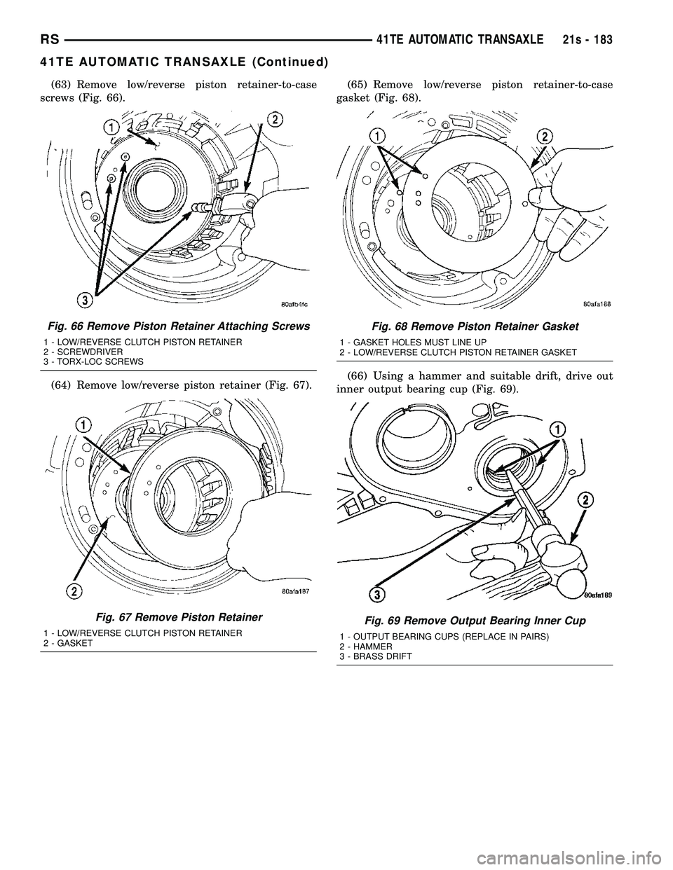
(63) Remove low/reverse piston retainer-to-case
screws (Fig. 66).
(64) Remove low/reverse piston retainer (Fig. 67). (65) Remove low/reverse piston retainer-to-case
gasket (Fig. 68).
(66) Using a hammer and suitable drift, drive out
inner output bearing cup (Fig. 69).
Fig. 66 Remove Piston Retainer Attaching Screws
1 - LOW/REVERSE CLUTCH PISTON RETAINER
2 - SCREWDRIVER
3 - TORX-LOC SCREWS
Fig. 67 Remove Piston Retainer
1 - LOW/REVERSE CLUTCH PISTON RETAINER
2 - GASKET
Fig. 68 Remove Piston Retainer Gasket
1 - GASKET HOLES MUST LINE UP
2 - LOW/REVERSE CLUTCH PISTON RETAINER GASKET
Fig. 69 Remove Output Bearing Inner Cup
1 - OUTPUT BEARING CUPS (REPLACE IN PAIRS)
2 - HAMMER
3 - BRASS DRIFT
RS 41TE AUTOMATIC TRANSAXLE21s - 183
41TE AUTOMATIC TRANSAXLE (Continued)