Page 1677 of 2585
(4) Apply park brake to allow park brake handle to
clear center console upon removal.
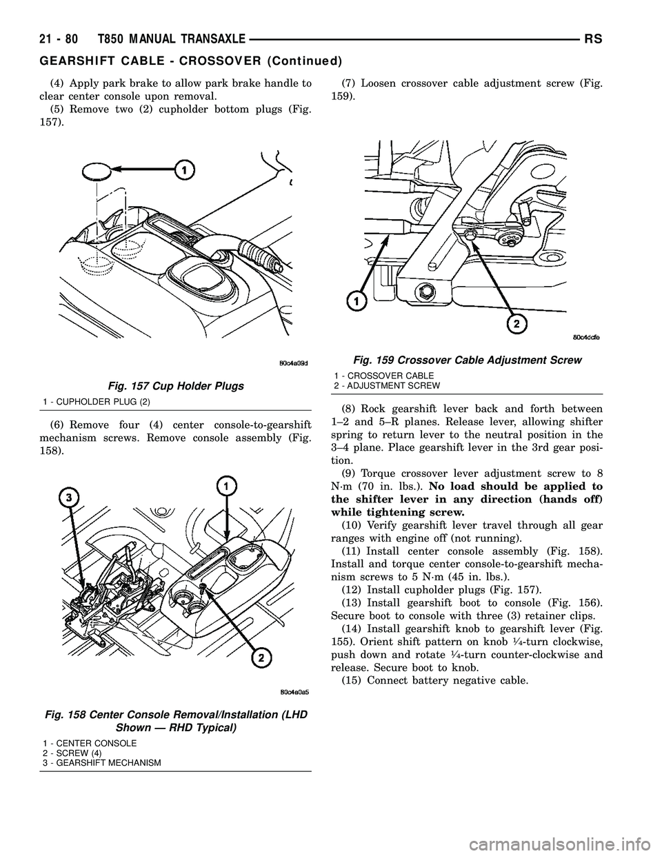
(5) Remove two (2) cupholder bottom plugs (Fig.
157).
(6) Remove four (4) center console-to-gearshift
mechanism screws. Remove console assembly (Fig.
158).(7) Loosen crossover cable adjustment screw (Fig.
159).
(8) Rock gearshift lever back and forth between
1±2 and 5±R planes. Release lever, allowing shifter
spring to return lever to the neutral position in the
3±4 plane. Place gearshift lever in the 3rd gear posi-
tion.
(9) Torque crossover lever adjustment screw to 8
N´m (70 in. lbs.).No load should be applied to
the shifter lever in any direction (hands off)
while tightening screw.
(10) Verify gearshift lever travel through all gear
ranges with engine off (not running).
(11) Install center console assembly (Fig. 158).
Install and torque center console-to-gearshift mecha-
nism screws to 5 N´m (45 in. lbs.).
(12) Install cupholder plugs (Fig. 157).
(13) Install gearshift boot to console (Fig. 156).
Secure boot to console with three (3) retainer clips.
(14) Install gearshift knob to gearshift lever (Fig.
155). Orient shift pattern on knob
1¤4-turn clockwise,
push down and rotate1¤4-turn counter-clockwise and
release. Secure boot to knob.
(15) Connect battery negative cable.
Fig. 157 Cup Holder Plugs
1 - CUPHOLDER PLUG (2)
Fig. 158 Center Console Removal/Installation (LHD
Shown Ð RHD Typical)
1 - CENTER CONSOLE
2 - SCREW (4)
3 - GEARSHIFT MECHANISM
Fig. 159 Crossover Cable Adjustment Screw
1 - CROSSOVER CABLE
2 - ADJUSTMENT SCREW
21 - 80 T850 MANUAL TRANSAXLERS
GEARSHIFT CABLE - CROSSOVER (Continued)
Page 1681 of 2585
(17) Raise vehicle on hoist.
(18) Remove selector cable from engine compart-
ment, then remove cable from passenger compart-
ment through opening in floor pan.
INSTALLATION
(1) From underneath vehicle, install gearshift
selector cable into passenger compartment through
floor pan hole. Install remainder of cable into posi-
tion in engine compartment.
(2) Lower vehicle.
(3) Install selector cable to mount bracket and
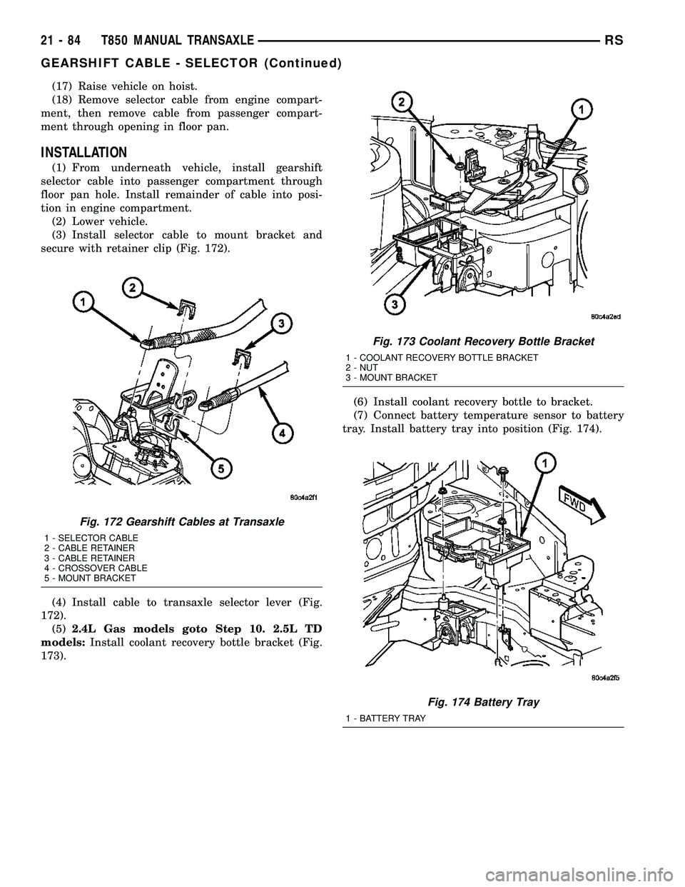
secure with retainer clip (Fig. 172).
(4) Install cable to transaxle selector lever (Fig.
172).
(5)2.4L Gas models goto Step 10. 2.5L TD
models:Install coolant recovery bottle bracket (Fig.
173).(6) Install coolant recovery bottle to bracket.
(7) Connect battery temperature sensor to battery
tray. Install battery tray into position (Fig. 174).
Fig. 172 Gearshift Cables at Transaxle
1 - SELECTOR CABLE
2 - CABLE RETAINER
3 - CABLE RETAINER
4 - CROSSOVER CABLE
5 - MOUNT BRACKET
Fig. 173 Coolant Recovery Bottle Bracket
1 - COOLANT RECOVERY BOTTLE BRACKET
2 - NUT
3 - MOUNT BRACKET
Fig. 174 Battery Tray
1 - BATTERY TRAY
21 - 84 T850 MANUAL TRANSAXLERS
GEARSHIFT CABLE - SELECTOR (Continued)
Page 1683 of 2585
(11) Install center console support bracket (Fig.
179). Torque support bracket-to-gearshift mechanism
screws to 12 N´m (108 in. lbs.).
(12) Install center console assembly (Fig. 180).
Install and torque center console-to-gearshift mecha-
nism screws to 5 N´m (45 in. lbs.).(13) Install cupholder plugs (Fig. 181).
(14) Install gearshift boot to console (Fig. 182).
Secure with three (3) retainer clips.
Fig. 179 Center Console Support Bracket
1 - BRACKET
2 - SCREW
3 - GEARSHIFT MECHANISM
Fig. 180 Center Console Removal/Installation (LHD
Shown Ð RHD Typical)
1 - CENTER CONSOLE
2 - SCREW (4)
3 - GEARSHIFT MECHANISM
Fig. 181 Cup Holder Plugs
1 - CUPHOLDER PLUG (2)
Fig. 182 Gearshift Boot Removal/Installation
1 - GEARSHIFT BOOT
2 - CENTER CONSOLE
21 - 86 T850 MANUAL TRANSAXLERS
GEARSHIFT CABLE - SELECTOR (Continued)
Page 1684 of 2585
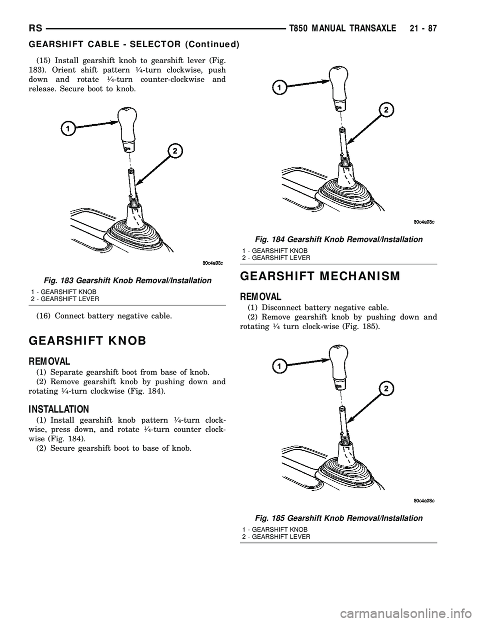
(15) Install gearshift knob to gearshift lever (Fig.
183). Orient shift pattern1¤4-turn clockwise, push
down and rotate1¤4-turn counter-clockwise and
release. Secure boot to knob.
(16) Connect battery negative cable.
GEARSHIFT KNOB
REMOVAL
(1) Separate gearshift boot from base of knob.
(2) Remove gearshift knob by pushing down and
rotating
1¤4-turn clockwise (Fig. 184).
INSTALLATION
(1) Install gearshift knob pattern1¤4-turn clock-
wise, press down, and rotate1¤4-turn counter clock-
wise (Fig. 184).
(2) Secure gearshift boot to base of knob.
GEARSHIFT MECHANISM
REMOVAL
(1) Disconnect battery negative cable.
(2) Remove gearshift knob by pushing down and
rotating
1¤4turn clock-wise (Fig. 185).
Fig. 183 Gearshift Knob Removal/Installation
1 - GEARSHIFT KNOB
2 - GEARSHIFT LEVER
Fig. 184 Gearshift Knob Removal/Installation
1 - GEARSHIFT KNOB
2 - GEARSHIFT LEVER
Fig. 185 Gearshift Knob Removal/Installation
1 - GEARSHIFT KNOB
2 - GEARSHIFT LEVER
RST850 MANUAL TRANSAXLE21-87
GEARSHIFT CABLE - SELECTOR (Continued)
Page 1689 of 2585
(7) Install cupholder plugs (Fig. 202).
(8) Install gearshift boot to console (Fig. 203).
Secure with three (3) retainer clips.(9) Install gearshift knob to gearshift lever (Fig.
204). Orient shift pattern1¤4-turn clockwise, push
down and rotate1¤4-turn counter-clockwise and
release. Secure boot to knob.
(10) Connect battery negative cable.
Fig. 202 Cup Holder Plugs
1 - CUPHOLDER PLUG (2)
Fig. 203 Gearshift Boot Removal/Installation
1 - GEARSHIFT BOOT
2 - CENTER CONSOLE
Fig. 204 Gearshift Knob Removal/Installation
1 - GEARSHIFT KNOB
2 - GEARSHIFT LEVER
21 - 92 T850 MANUAL TRANSAXLERS
GEARSHIFT MECHANISM (Continued)
Page 1691 of 2585
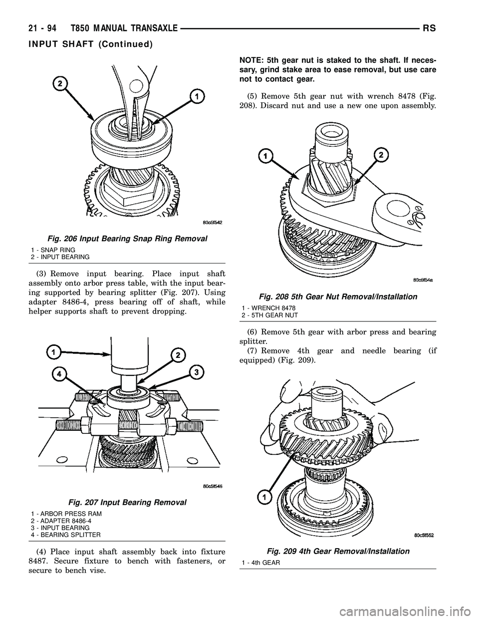
(3) Remove input bearing. Place input shaft
assembly onto arbor press table, with the input bear-
ing supported by bearing splitter (Fig. 207). Using
adapter 8486-4, press bearing off of shaft, while
helper supports shaft to prevent dropping.
(4) Place input shaft assembly back into fixture
8487. Secure fixture to bench with fasteners, or
secure to bench vise.NOTE: 5th gear nut is staked to the shaft. If neces-
sary, grind stake area to ease removal, but use care
not to contact gear.
(5) Remove 5th gear nut with wrench 8478 (Fig.
208). Discard nut and use a new one upon assembly.
(6) Remove 5th gear with arbor press and bearing
splitter.
(7) Remove 4th gear and needle bearing (if
equipped) (Fig. 209).
Fig. 206 Input Bearing Snap Ring Removal
1 - SNAP RING
2 - INPUT BEARING
Fig. 207 Input Bearing Removal
1 - ARBOR PRESS RAM
2 - ADAPTER 8486-4
3 - INPUT BEARING
4 - BEARING SPLITTER
Fig. 208 5th Gear Nut Removal/Installation
1 - WRENCH 8478
2 - 5TH GEAR NUT
Fig. 209 4th Gear Removal/Installation
1 - 4th GEAR
21 - 94 T850 MANUAL TRANSAXLERS
INPUT SHAFT (Continued)
Page 1722 of 2585
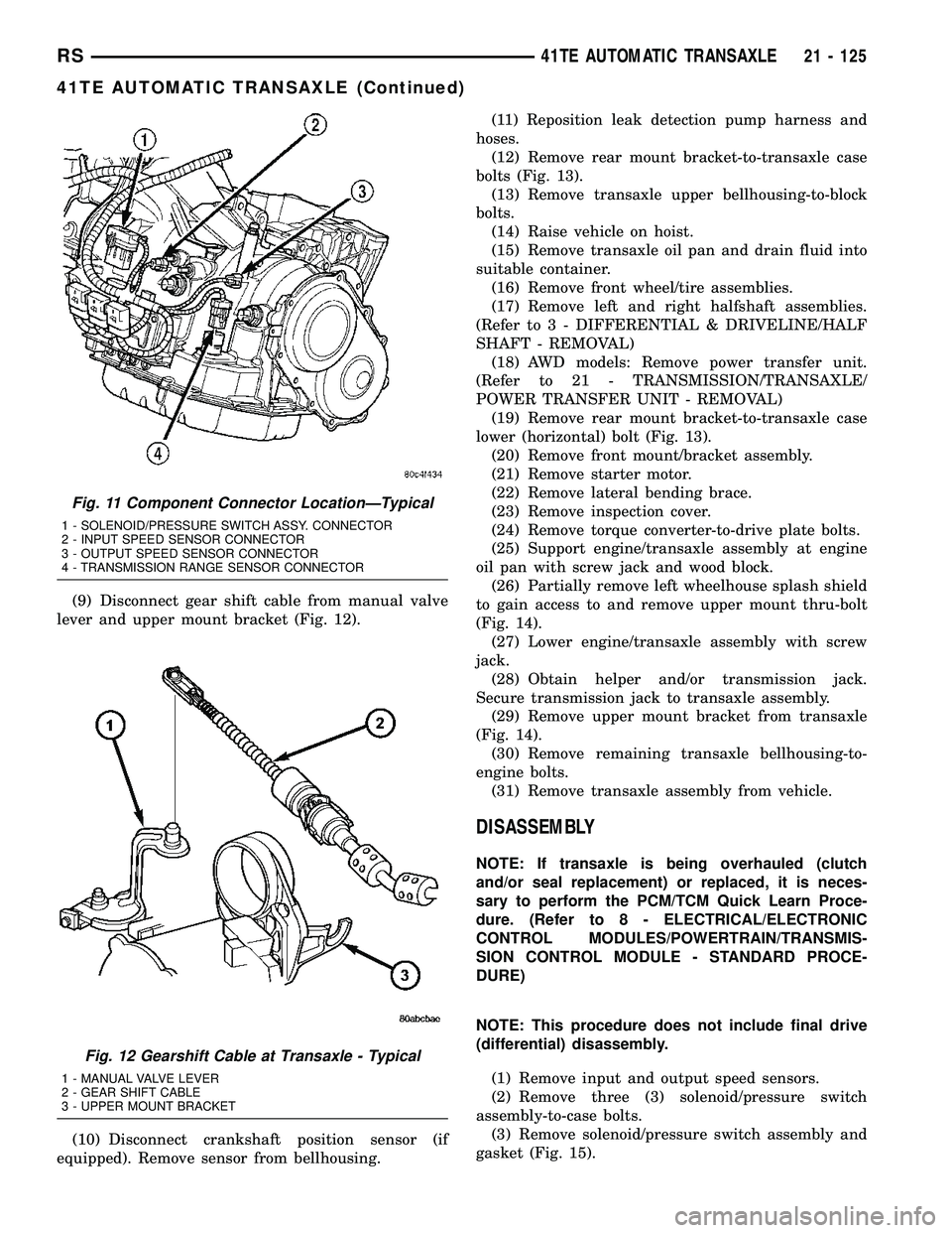
(9) Disconnect gear shift cable from manual valve
lever and upper mount bracket (Fig. 12).
(10) Disconnect crankshaft position sensor (if
equipped). Remove sensor from bellhousing.(11) Reposition leak detection pump harness and
hoses.
(12) Remove rear mount bracket-to-transaxle case
bolts (Fig. 13).
(13) Remove transaxle upper bellhousing-to-block
bolts.
(14) Raise vehicle on hoist.
(15) Remove transaxle oil pan and drain fluid into
suitable container.
(16) Remove front wheel/tire assemblies.
(17) Remove left and right halfshaft assemblies.
(Refer to 3 - DIFFERENTIAL & DRIVELINE/HALF
SHAFT - REMOVAL)
(18) AWD models: Remove power transfer unit.
(Refer to 21 - TRANSMISSION/TRANSAXLE/
POWER TRANSFER UNIT - REMOVAL)
(19) Remove rear mount bracket-to-transaxle case
lower (horizontal) bolt (Fig. 13).
(20) Remove front mount/bracket assembly.
(21) Remove starter motor.
(22) Remove lateral bending brace.
(23) Remove inspection cover.
(24) Remove torque converter-to-drive plate bolts.
(25) Support engine/transaxle assembly at engine
oil pan with screw jack and wood block.
(26) Partially remove left wheelhouse splash shield
to gain access to and remove upper mount thru-bolt
(Fig. 14).
(27) Lower engine/transaxle assembly with screw
jack.
(28) Obtain helper and/or transmission jack.
Secure transmission jack to transaxle assembly.
(29) Remove upper mount bracket from transaxle
(Fig. 14).
(30) Remove remaining transaxle bellhousing-to-
engine bolts.
(31) Remove transaxle assembly from vehicle.
DISASSEMBLY
NOTE: If transaxle is being overhauled (clutch
and/or seal replacement) or replaced, it is neces-
sary to perform the PCM/TCM Quick Learn Proce-
dure. (Refer to 8 - ELECTRICAL/ELECTRONIC
CONTROL MODULES/POWERTRAIN/TRANSMIS-
SION CONTROL MODULE - STANDARD PROCE-
DURE)
NOTE: This procedure does not include final drive
(differential) disassembly.
(1) Remove input and output speed sensors.
(2) Remove three (3) solenoid/pressure switch
assembly-to-case bolts.
(3) Remove solenoid/pressure switch assembly and
gasket (Fig. 15).
Fig. 11 Component Connector LocationÐTypical
1 - SOLENOID/PRESSURE SWITCH ASSY. CONNECTOR
2 - INPUT SPEED SENSOR CONNECTOR
3 - OUTPUT SPEED SENSOR CONNECTOR
4 - TRANSMISSION RANGE SENSOR CONNECTOR
Fig. 12 Gearshift Cable at Transaxle - Typical
1 - MANUAL VALVE LEVER
2 - GEAR SHIFT CABLE
3 - UPPER MOUNT BRACKET
RS41TE AUTOMATIC TRANSAXLE21 - 125
41TE AUTOMATIC TRANSAXLE (Continued)
Page 1763 of 2585
(67) Install oil pan-to-case bolts and torque to 19
N´m (165 in. lbs.).
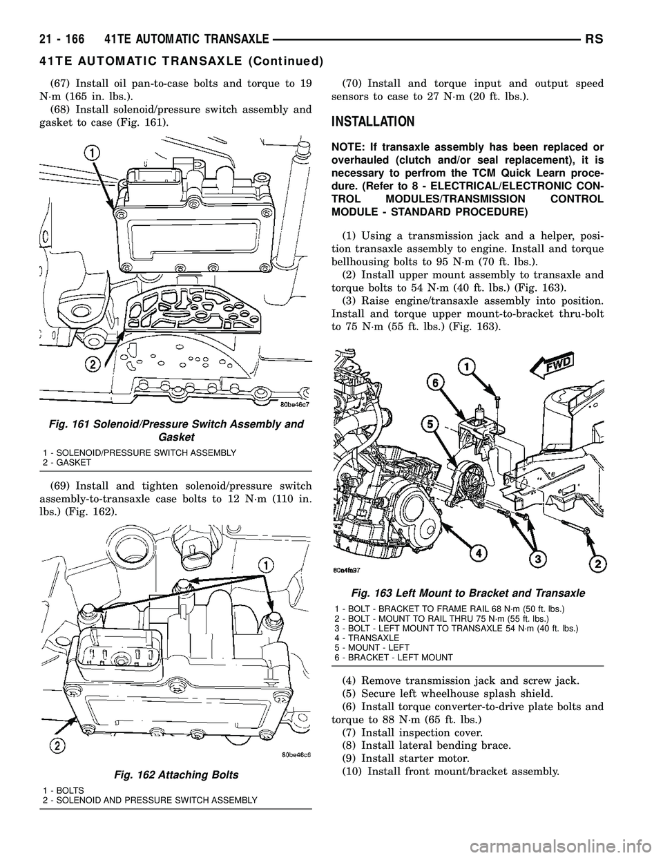
(68) Install solenoid/pressure switch assembly and
gasket to case (Fig. 161).
(69) Install and tighten solenoid/pressure switch
assembly-to-transaxle case bolts to 12 N´m (110 in.
lbs.) (Fig. 162).(70) Install and torque input and output speed
sensors to case to 27 N´m (20 ft. lbs.).
INSTALLATION
NOTE: If transaxle assembly has been replaced or
overhauled (clutch and/or seal replacement), it is
necessary to perfrom the TCM Quick Learn proce-
dure. (Refer to 8 - ELECTRICAL/ELECTRONIC CON-
TROL MODULES/TRANSMISSION CONTROL
MODULE - STANDARD PROCEDURE)
(1) Using a transmission jack and a helper, posi-
tion transaxle assembly to engine. Install and torque
bellhousing bolts to 95 N´m (70 ft. lbs.).
(2) Install upper mount assembly to transaxle and
torque bolts to 54 N´m (40 ft. lbs.) (Fig. 163).
(3) Raise engine/transaxle assembly into position.
Install and torque upper mount-to-bracket thru-bolt
to 75 N´m (55 ft. lbs.) (Fig. 163).
(4) Remove transmission jack and screw jack.
(5) Secure left wheelhouse splash shield.
(6) Install torque converter-to-drive plate bolts and
torque to 88 N´m (65 ft. lbs.)
(7) Install inspection cover.
(8) Install lateral bending brace.
(9) Install starter motor.
(10) Install front mount/bracket assembly.
Fig. 161 Solenoid/Pressure Switch Assembly and
Gasket
1 - SOLENOID/PRESSURE SWITCH ASSEMBLY
2 - GASKET
Fig. 162 Attaching Bolts
1 - BOLTS
2 - SOLENOID AND PRESSURE SWITCH ASSEMBLY
Fig. 163 Left Mount to Bracket and Transaxle
1 - BOLT - BRACKET TO FRAME RAIL 68 N´m (50 ft. lbs.)
2 - BOLT - MOUNT TO RAIL THRU 75 N´m (55 ft. lbs.)
3 - BOLT - LEFT MOUNT TO TRANSAXLE 54 N´m (40 ft. lbs.)
4 - TRANSAXLE
5 - MOUNT - LEFT
6 - BRACKET - LEFT MOUNT
21 - 166 41TE AUTOMATIC TRANSAXLERS
41TE AUTOMATIC TRANSAXLE (Continued)