Page 1630 of 2585
REMOVAL - 2.5L TD
(1) Raise hood.
(2) Disconnect both battery cables.
(3) Remove battery thermal shield (Fig. 15).
(4) Remove battery hold down bolt, clamp, and
battery (Fig. 16).(5) Remove battery tray (Fig. 17). Disconnect bat-
tery temperature sensor.
(6) Remove coolant recovery bottle from bracket.
(7) Remove coolant recovery bottle mounting
bracket (Fig. 18).
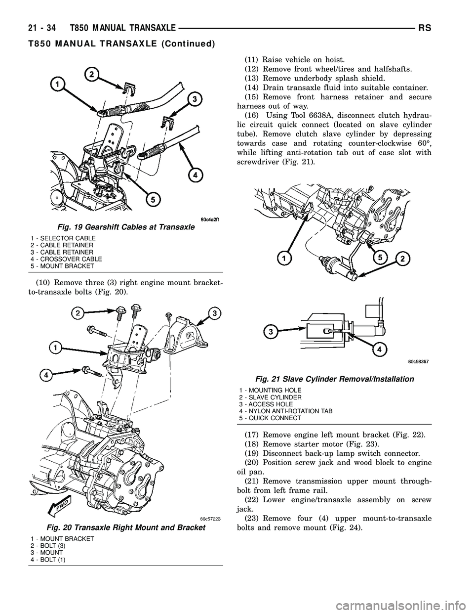
(8) Disconnect gearshift cables from shift levers/
cover assembly (Fig. 19).
(9) Remove gearshift cable retaining clips from
mounting bracket (Fig. 19). Remove cables and
secure out of way.
Fig. 15 Battery Thermal Shield
1 - BATTERY THERMAL SHIELD
Fig. 16 Battery and Hold-Down Clamp
1 - BATTERY
2 - HOLD-DOWN CLAMP
Fig. 17 Battery Tray
1 - BATTERY TRAY
Fig. 18 Coolant Recovery Bottle Bracket
1 - COOLANT RECOVERY BOTTLE BRACKET
2 - NUT
3 - MOUNT BRACKET
RST850 MANUAL TRANSAXLE21-33
T850 MANUAL TRANSAXLE (Continued)
Page 1631 of 2585

(10) Remove three (3) right engine mount bracket-
to-transaxle bolts (Fig. 20).(11) Raise vehicle on hoist.
(12) Remove front wheel/tires and halfshafts.
(13) Remove underbody splash shield.
(14) Drain transaxle fluid into suitable container.
(15) Remove front harness retainer and secure
harness out of way.
(16) Using Tool 6638A, disconnect clutch hydrau-
lic circuit quick connect (located on slave cylinder
tube). Remove clutch slave cylinder by depressing
towards case and rotating counter-clockwise 60É,
while lifting anti-rotation tab out of case slot with
screwdriver (Fig. 21).
(17) Remove engine left mount bracket (Fig. 22).
(18) Remove starter motor (Fig. 23).
(19) Disconnect back-up lamp switch connector.
(20) Position screw jack and wood block to engine
oil pan.
(21) Remove transmission upper mount through-
bolt from left frame rail.
(22) Lower engine/transaxle assembly on screw
jack.
(23) Remove four (4) upper mount-to-transaxle
bolts and remove mount (Fig. 24).
Fig. 19 Gearshift Cables at Transaxle
1 - SELECTOR CABLE
2 - CABLE RETAINER
3 - CABLE RETAINER
4 - CROSSOVER CABLE
5 - MOUNT BRACKET
Fig. 20 Transaxle Right Mount and Bracket
1 - MOUNT BRACKET
2 - BOLT (3)
3 - MOUNT
4 - BOLT (1)
Fig. 21 Slave Cylinder Removal/Installation
1 - MOUNTING HOLE
2 - SLAVE CYLINDER
3 - ACCESS HOLE
4 - NYLON ANTI-ROTATION TAB
5 - QUICK CONNECT
21 - 34 T850 MANUAL TRANSAXLERS
T850 MANUAL TRANSAXLE (Continued)
Page 1632 of 2585
(24) Obtain helper and transmission jack. Secure
transaxle to transmission jack and remove transaxle-
to-engine bolts.
(25) Remove transaxle from engine (Fig. 25).
(26) Inspect clutch, clutch release components, and
flywheel.
DISASSEMBLY
(1) Remove clutch release lever and bearing (Fig.
26). Inspect release lever pivot balls and replace if
necessary (Fig. 27). Use slide hammer C-3752 and
remover/installer 6891 (Fig. 28) if pivot ball replace-
ment is necessary.
Fig. 22 Left Mount Bracket Removal/Installation
1 - BOLT (2)
2 - MOUNT BRACKET
3 - BOLT (2)
Fig. 23 Starter Motor Removal/Installation
1 - STARTER MOTOR
2 - BOLT (3)
Fig. 24 Transaxle Upper Mount
1 - MOUNT
2 - BOLT (4)
RST850 MANUAL TRANSAXLE21-35
T850 MANUAL TRANSAXLE (Continued)
Page 1649 of 2585

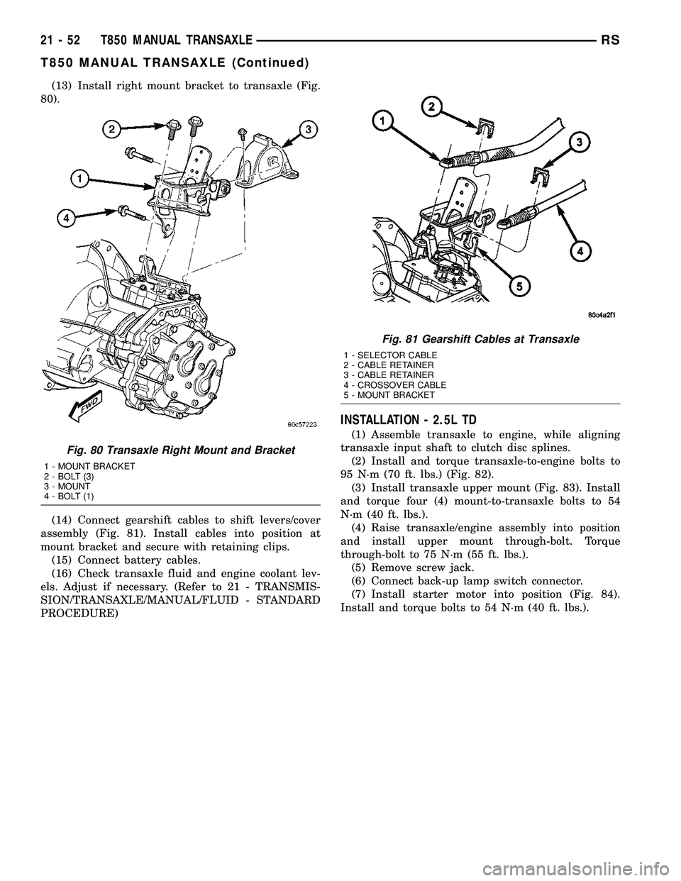
(13) Install right mount bracket to transaxle (Fig.
80).
(14) Connect gearshift cables to shift levers/cover
assembly (Fig. 81). Install cables into position at
mount bracket and secure with retaining clips.
(15) Connect battery cables.
(16) Check transaxle fluid and engine coolant lev-
els. Adjust if necessary. (Refer to 21 - TRANSMIS-
SION/TRANSAXLE/MANUAL/FLUID - STANDARD
PROCEDURE)
INSTALLATION - 2.5L TD
(1) Assemble transaxle to engine, while aligning
transaxle input shaft to clutch disc splines.
(2) Install and torque transaxle-to-engine bolts to
95 N´m (70 ft. lbs.) (Fig. 82).
(3) Install transaxle upper mount (Fig. 83). Install
and torque four (4) mount-to-transaxle bolts to 54
N´m (40 ft. lbs.).
(4) Raise transaxle/engine assembly into position
and install upper mount through-bolt. Torque
through-bolt to 75 N´m (55 ft. lbs.).
(5) Remove screw jack.
(6) Connect back-up lamp switch connector.
(7) Install starter motor into position (Fig. 84).
Install and torque bolts to 54 N´m (40 ft. lbs.).
Fig. 80 Transaxle Right Mount and Bracket
1 - MOUNT BRACKET
2 - BOLT (3)
3 - MOUNT
4 - BOLT (1)
Fig. 81 Gearshift Cables at Transaxle
1 - SELECTOR CABLE
2 - CABLE RETAINER
3 - CABLE RETAINER
4 - CROSSOVER CABLE
5 - MOUNT BRACKET
21 - 52 T850 MANUAL TRANSAXLERS
T850 MANUAL TRANSAXLE (Continued)
Page 1651 of 2585

(8) Install engine front mount bracket. Install and
torque bracket-to-transaxle bolts to 102 N´m (75 ft.
lbs.). Install and torque bracket-to-engine bolts to 68
N´m (50 ft. lbs.). Torque through-bolt and nut to 68
N´m (50 ft. lbs.).
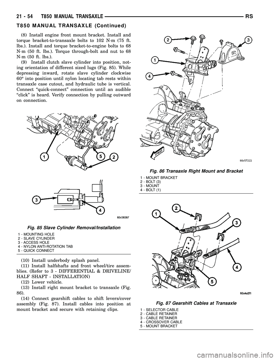
(9) Install clutch slave cylinder into position, not-
ing orientation of different sized lugs (Fig. 85). While
depressing inward, rotate slave cylinder clockwise
60É into position until nylon locating tab rests within
transaxle case cutout, and hydraulic tube is vertical.
Connect ªquick-connectº connection until an audible
ªclickº is heard. Verify connection by pulling outward
on connection.
(10) Install underbody splash panel.
(11) Install halfshafts and front wheel/tire assem-
blies. (Refer to 3 - DIFFERENTIAL & DRIVELINE/
HALF SHAFT - INSTALLATION)
(12) Lower vehicle.
(13) Install right mount bracket to transaxle (Fig.
86).
(14) Connect gearshift cables to shift levers/cover
assembly (Fig. 87). Install cables into position at
mount bracket and secure with retaining clips.
Fig. 85 Slave Cylinder Removal/Installation
1 - MOUNTING HOLE
2 - SLAVE CYLINDER
3 - ACCESS HOLE
4 - NYLON ANTI-ROTATION TAB
5 - QUICK CONNECT
Fig. 86 Transaxle Right Mount and Bracket
1 - MOUNT BRACKET
2 - BOLT (3)
3 - MOUNT
4 - BOLT (1)
Fig. 87 Gearshift Cables at Transaxle
1 - SELECTOR CABLE
2 - CABLE RETAINER
3 - CABLE RETAINER
4 - CROSSOVER CABLE
5 - MOUNT BRACKET
21 - 54 T850 MANUAL TRANSAXLERS
T850 MANUAL TRANSAXLE (Continued)
Page 1670 of 2585
INSTALLATION
(1) Install gearshift boot to console and secure
with three (3) retaining clips (Fig. 130).
(2) Install gearshift knob (Fig. 129). Orient shift
pattern
1¤4-turn clockwise, press down, and rotate1¤4-
turn counter-clockwise.
(3) Secure gearshift boot to base of knob.
GEARSHIFT CABLE -
CROSSOVER
REMOVAL
(1) Disconnect battery negative cable.
(2) Remove gearshift knob by pushing down and
rotating
1¤4-turn clock-wise (Fig. 131).
(3) Remove gearshift boot from center console by
disengaging at three (3) retaining clips (Fig. 132).
(4) Apply park brake to allow park brake handle to
clear center console upon removal.
(5) Remove two (2) cupholder bottom plugs (Fig.
133).
Fig. 131 Gearshift Knob Removal/Installation
1 - GEARSHIFT KNOB
2 - GEARSHIFT LEVER
Fig. 132 Gearshift Boot Removal/Installation
1 - GEARSHIFT BOOT
2 - CENTER CONSOLE
Fig. 133 Cup Holder Plugs
1 - CUPHOLDER PLUG (2)
RST850 MANUAL TRANSAXLE21-73
GEARSHIFT BOOT (Continued)
Page 1673 of 2585

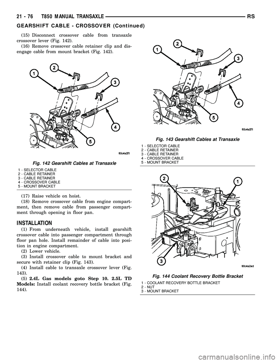
(15) Disconnect crossover cable from transaxle
crossover lever (Fig. 142).
(16) Remove crossover cable retainer clip and dis-
engage cable from mount bracket (Fig. 142).
(17) Raise vehicle on hoist.
(18) Remove crossover cable from engine compart-
ment, then remove cable from passenger compart-
ment through opening in floor pan.
INSTALLATION
(1) From underneath vehicle, install gearshift
crossover cable into passenger compartment through
floor pan hole. Install remainder of cable into posi-
tion in engine compartment.
(2) Lower vehicle.
(3) Install crossover cable to mount bracket and
secure with retainer clip (Fig. 143).
(4) Install cable to transaxle crossover lever (Fig.
143).
(5)2.4L Gas models goto Step 10. 2.5L TD
Models:Install coolant recovery bottle bracket (Fig.
144).
Fig. 142 Gearshift Cables at Transaxle
1 - SELECTOR CABLE
2 - CABLE RETAINER
3 - CABLE RETAINER
4 - CROSSOVER CABLE
5 - MOUNT BRACKET
Fig. 143 Gearshift Cables at Transaxle
1 - SELECTOR CABLE
2 - CABLE RETAINER
3 - CABLE RETAINER
4 - CROSSOVER CABLE
5 - MOUNT BRACKET
Fig. 144 Coolant Recovery Bottle Bracket
1 - COOLANT RECOVERY BOTTLE BRACKET
2 - NUT
3 - MOUNT BRACKET
21 - 76 T850 MANUAL TRANSAXLERS
GEARSHIFT CABLE - CROSSOVER (Continued)
Page 1676 of 2585
(15) Install gearshift boot to console (Fig. 153).
Secure with three (3) retainer clips.
(16) Install gearshift knob to gearshift lever (Fig.
154). Orient shift pattern
1¤4-turn clockwise, push
down and rotate1¤4-turn counter-clockwise and
release. Secure boot to knob.
(17) Connect battery negative cable.
ADJUSTMENTS
ADJUSTMENT
(1) Disconnect battery negative cable.
(2) Remove gearshift knob by pushing down and
rotating
1¤4-turn clock-wise (Fig. 155).
(3) Remove gearshift boot from center console by
disengaging at three (3) retaining clips (Fig. 156).
Fig. 153 Gearshift Boot Removal/Installation
1 - GEARSHIFT BOOT
2 - CENTER CONSOLE
Fig. 154 Gearshift Knob Removal/Installation
1 - GEARSHIFT KNOB
2 - GEARSHIFT LEVER
Fig. 155 Gearshift Knob Removal/Installation
1 - GEARSHIFT KNOB
2 - GEARSHIFT LEVER
Fig. 156 Gearshift Boot Removal/Installation
1 - GEARSHIFT BOOT
2 - CENTER CONSOLE
RST850 MANUAL TRANSAXLE21-79
GEARSHIFT CABLE - CROSSOVER (Continued)