2004 CHRYSLER VOYAGER heater
[x] Cancel search: heaterPage 2500 of 2585
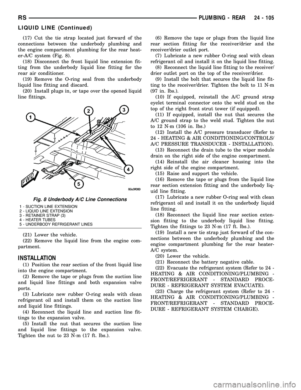
(17) Cut the tie strap located just forward of the
connections between the underbody plumbing and
the engine compartment plumbing for the rear heat-
er-A/C system (Fig. 8).
(18) Disconnect the front liquid line extension fit-
ting from the underbody liquid line fitting for the
rear air conditioner.
(19) Remove the O-ring seal from the underbody
liquid line fitting and discard.
(20) Install plugs in, or tape over the opened liquid
line fittings.
(21) Lower the vehicle.
(22) Remove the liquid line from the engine com-
partment.
INSTALLATION
(1) Position the rear section of the front liquid line
into the engine compartment.
(2) Remove the tape or plugs from the suction line
and liquid line fittings and both expansion valve
ports.
(3) Lubricate new rubber O-ring seals with clean
refrigerant oil and install them on the suction line
and liquid line fittings.
(4) Reconnect the liquid line and suction line fit-
tings to the expansion valve.
(5) Install the nut that secures the suction line
and liquid line fittings to the expansion valve.
Tighten the nut to 23 N´m (17 ft. lbs.).(6) Remove the tape or plugs from the liquid line
rear section fitting for the receiver/drier and the
receiver/drier outlet port.
(7) Lubricate a new rubber O-ring seal with clean
refrigerant oil and install it on the liquid line fitting.
(8) Reconnect the liquid line fitting to the receiver/
drier outlet port on the top of the receiver/drier.
(9) Install the bolt that secures the liquid line fit-
ting to the receiver/drier. Tighten the bolt to 11 N´m
(97 in. lbs.).
(10) If equipped, reinstall the A/C ground strap
eyelet terminal connector onto the weld stud on the
top of the right front strut tower (if equipped).
(11) If equipped, install the nut that secures the
A/C ground strap to the weld stud. Tighten the nut
to 12 N´m (106 in. lbs.)
(12) Install the A/C pressure transducer (Refer to
24 - HEATING & AIR CONDITIONING/CONTROLS/
A/C PRESSURE TRANSDUCER - INSTALLATION).
(13) Reconnect the drain tube to the wiper module
drain on the right side of the engine compartment.
(14) Reinstall the air cleaner housing into the
right side of the engine compartment.
(15) Raise and support the vehicle.
(16) Remove the tape or plugs from the liquid line
rear section extension fitting and the underbody liq-
uid line fitting.
(17) Lubricate a new rubber O-ring seal with clean
refrigerant oil and install it on the underbody liquid
line fitting.
(18) Reconnect the liquid line rear section exten-
sion fitting to the underbody liquid line fitting.
Tighten the fittings to 23 N´m (17 ft. lbs.).
(19) Install a new tie strap just forward of the con-
nections between the underbody plumbing and the
engine compartment plumbing for the rear heater-
A/C system.
(20) Lower the vehicle.
(21) Reconnect the battery negative cable.
(22) Evacuate the refrigerant system (Refer to 24 -
HEATING & AIR CONDITIONING/PLUMBING -
FRONT/REFRIGERANT - STANDARD PROCE-
DURE - REFRIGERANT SYSTEM EVACUATE).
(23) Charge the refrigerant system (Refer to 24 -
HEATING & AIR CONDITIONING/PLUMBING -
FRONT/REFRIGERANT - STANDARD PROCE-
DURE - REFRIGERANT SYSTEM CHARGE).
Fig. 8 Underbody A/C Line Connections
1 - SUCTION LINE EXTENSION
2 - LIQUID LINE EXTENSION
3 - RETAINER STRAP (3)
4 - HEATER TUBES
5 - UNDERBODY REFRIGERANT LINES
RSPLUMBING - REAR24 - 105
LIQUID LINE (Continued)
Page 2501 of 2585
SUCTION LINE
REMOVAL
On models equipped with the optional rear A/C
system, the front air conditioner suction line also
includes a suction line hose and tube extension that
connects the front suction line to the underbody suc-
tion line for the rear A/C system.
WARNING: REFER TO THE APPLICABLE WARN-
INGS AND CAUTIONS FOR THIS SYSTEM BEFORE
PERFORMING THE FOLLOWING OPERATION (Refer
to 24 - HEATING & AIR CONDITIONING/PLUMBING -
FRONT - WARNING - A/C PLUMBING) and (Refer to
24 - HEATING & AIR CONDITIONING/PLUMBING -
FRONT - CAUTION - A/C PLUMBING).
(1) Recover the refrigerant from the refrigerant
system (Refer to 24 - HEATING & AIR CONDITION-
ING/PLUMBING - FRONT/REFRIGERANT - STAN-
DARD PROCEDURE - REFRIGERANT
RECOVERY).
(2) Disconnect and isolate the battery negative
cable.
(3) Remove the air cleaner top cover and snorkel
from the air cleaner housing located on the right side
of the engine compartment.
(4) Disconnect the drain tube from the wiper mod-
ule drain on the right side of the engine compart-
ment.
(5) Remove the nut that secures the suction line
fitting to the top of the compressor.
(6) Disconnect the suction line fitting from the
compressor suction port.
(7) Remove the seal from the suction line fitting
and discard.
(8) Install plugs in, or tape over the opened suc-
tion line fitting and the compressor suction port.
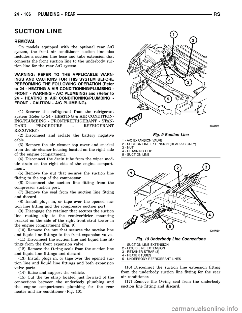
(9) Disengage the retainer that secures the suction
line routing clip to the receiver/drier mounting
bracket on the side of the right front strut tower in
the engine compartment (Fig. 9).
(10) Remove the nut that secures the suction line
and liquid line fittings to the front expansion valve.
(11) Disconnect the suction line and liquid line fit-
tings from the front expansion valve.
(12) Remove the O-ring seals from the suction line
and liquid line fittings and discard.
(13) Install plugs in, or tape over the opened suc-
tion line and liquid line fittings and both expansion
valve ports.
(14) Raise and support the vehicle.
(15) Cut the tie strap located just forward of the
connections between the underbody plumbing and
the engine compartment plumbing for the rear
heater and air conditioner (Fig. 10).(16) Disconnect the suction line extension fitting
from the underbody suction line fitting for the rear
air conditioner.
(17) Remove the O-ring seal from the underbody
suction line fitting and discard.
Fig. 9 Suction Line
1 - A/C EXPANSION VALVE
2 - SUCTION LINE EXTENSION (REAR A/C ONLY)
3 - NUT
4 - RETAINING CLIP
5 - SUCTION LINE
Fig. 10 Underbody Line Connections
1 - SUCTION LINE EXTENSION
2 - LIQUID LINE EXTENSION
3 - RETAINER STRAP (3)
4 - HEATER TUBES
5 - UNDERBODY REFRIGERANT LINES
24 - 106 PLUMBING - REARRS
Page 2502 of 2585
(18) Install plugs in, or tape over the opened suc-
tion line fittings.
(19) Lower the vehicle.
(20) Remove the suction line from the engine com-
partment.
INSTALLATION
(1) Position the suction line into the engine com-
partment.
(2) Remove the tape or plugs from the suction line
and liquid line fittings and both expansion valve
ports.
(3) Lubricate new rubber O-ring seals with clean
refrigerant oil and install them on the suction line
and liquid line fittings.
(4) Reconnect the liquid line and suction line fit-
tings to the expansion valve.
(5) Install the nut that secures the suction line
and liquid line fittings to the front expansion valve.
Tighten the nut to 23 N´m (17 ft. lbs.).
(6) Engage the retainer that secures the suction
line routing clip to the receiver/drier mounting
bracket on the side of the right front strut tower in
the engine compartment.
(7) Remove the tape or plugs from the compressor
suction port and the suction line fitting.
(8) Lubricate a new rubber O-ring seal with clean
refrigerant oil and install it on the suction line fit-
ting.
(9) Reconnect the suction line fitting to the com-
pressor suction port.
(10) Install the nut that secures the suction line
fitting to the A/C compressor. Tighten the nut to 23
N´m (17 ft. lbs.).
(11) Reconnect the drain tube to the wiper module
drain on the right side of the engine compartment.
(12) Reinstall the air cleaner top cover and snorkel
onto the air cleaner housing located on the right side
of the engine compartment.
(13) Reconnect the battery negative cable.
(14) Raise and support the vehicle.
(15) Remove the tape or plugs from the suction
line extension fitting and the underbody suction line
fitting.(16) Lubricate a new rubber O-ring seal with clean
refrigerant oil and install it on the underbody suction
line fitting.
(17) Reconnect the suction line extension fitting to
the underbody suction line fitting. Tighten the fitting
to 23 N´m (17 ft. lbs.).
(18) Install a new tie strap just forward of the con-
nections between the underbody plumbing and the
engine compartment plumbing for the rear heater
and air conditioner.
(19) Lower the vehicle.
(20) Evacuate the refrigerant system (Refer to 24 -
HEATING & AIR CONDITIONING/PLUMBING -
FRONT/REFRIGERANT - STANDARD PROCE-
DURE - REFRIGERANT SYSTEM EVACUATE).
(21) Charge the refrigerant system (Refer to 24 -
HEATING & AIR CONDITIONING/PLUMBING -
FRONT/REFRIGERANT - STANDARD PROCE-
DURE - REFRIGERANT SYSTEM CHARGE).
UNDERBODY LINES
DESCRIPTION
The underbody heater-A/C plumbing is used only
on models with the optional rear heater-A/C system
(Fig. 11). The underbody suction line, liquid line, and
heater tubes can each be serviced separately.
OPERATION
The rear heater and A/C lines are all serviced as
individual pieces. When disconnecting any line or
block ensure that the area around it is clean of any
contaminations that can get in to the system (Fig.
12), (Fig. 13), (Fig. 15), (Fig. 14) and (Fig. 16).
Any kinks or sharp bends in the rear heater-A/C
unit plumbing will reduce the capacity of the entire
heating and air conditioning system. Kinks and
sharp bends reduce the system flow. High pressures
are produced in the refrigerant system when the air
conditioning compressor is operating. High tempera-
ture coolant is present in the heater plumbing when
the engine is operating. Extreme care must be exer-
cised o make sure that each of the plumbing connec-
tions is pressure-tight and leak free.
RSPLUMBING - REAR24 - 107
SUCTION LINE (Continued)
Page 2503 of 2585
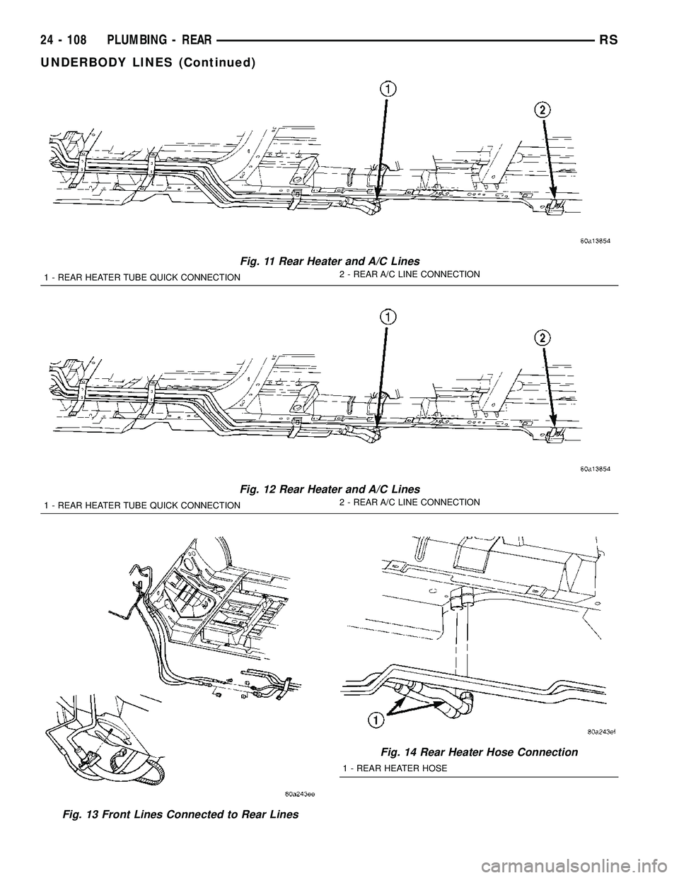
Fig. 11 Rear Heater and A/C Lines
1 - REAR HEATER TUBE QUICK CONNECTION2 - REAR A/C LINE CONNECTION
Fig. 12 Rear Heater and A/C Lines
1 - REAR HEATER TUBE QUICK CONNECTION2 - REAR A/C LINE CONNECTION
Fig. 13 Front Lines Connected to Rear Lines
Fig. 14 Rear Heater Hose Connection
1 - REAR HEATER HOSE
24 - 108 PLUMBING - REARRS
UNDERBODY LINES (Continued)
Page 2504 of 2585
REMOVAL
REMOVAL - UNDERBODY HEATER TUBES
WARNING: REFER TO THE APPLICABLE WARN-
INGS AND CAUTIONS FOR THIS SYSTEM BEFORE
PERFORMING THE FOLLOWING OPERATION (Refer
to 24 - HEATING & AIR CONDITIONING/PLUMBING -
WARNING).
(1) Drain the engine cooling system (Refer to 7 -
COOLING - STANDARD PROCEDURE - COOLING
SYSTEM DRAIN).
(2) Raise and support vehicle.
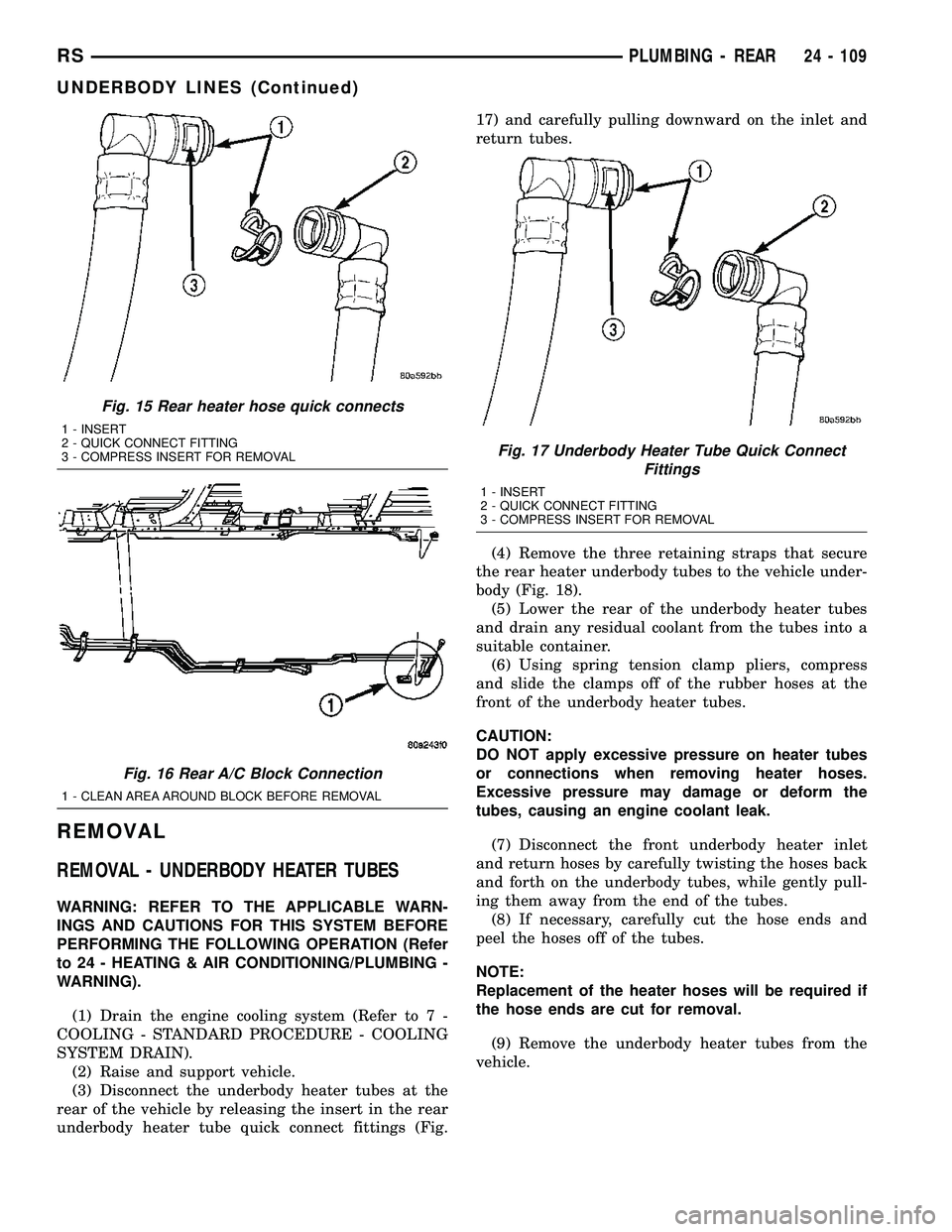
(3) Disconnect the underbody heater tubes at the
rear of the vehicle by releasing the insert in the rear
underbody heater tube quick connect fittings (Fig.17) and carefully pulling downward on the inlet and
return tubes.
(4) Remove the three retaining straps that secure
the rear heater underbody tubes to the vehicle under-
body (Fig. 18).
(5) Lower the rear of the underbody heater tubes
and drain any residual coolant from the tubes into a
suitable container.
(6) Using spring tension clamp pliers, compress
and slide the clamps off of the rubber hoses at the
front of the underbody heater tubes.
CAUTION:
DO NOT apply excessive pressure on heater tubes
or connections when removing heater hoses.
Excessive pressure may damage or deform the
tubes, causing an engine coolant leak.
(7) Disconnect the front underbody heater inlet
and return hoses by carefully twisting the hoses back
and forth on the underbody tubes, while gently pull-
ing them away from the end of the tubes.
(8) If necessary, carefully cut the hose ends and
peel the hoses off of the tubes.
NOTE:
Replacement of the heater hoses will be required if
the hose ends are cut for removal.
(9) Remove the underbody heater tubes from the
vehicle.
Fig. 15 Rear heater hose quick connects
1 - INSERT
2 - QUICK CONNECT FITTING
3 - COMPRESS INSERT FOR REMOVAL
Fig. 16 Rear A/C Block Connection
1 - CLEAN AREA AROUND BLOCK BEFORE REMOVAL
Fig. 17 Underbody Heater Tube Quick Connect
Fittings
1 - INSERT
2 - QUICK CONNECT FITTING
3 - COMPRESS INSERT FOR REMOVAL
RSPLUMBING - REAR24 - 109
UNDERBODY LINES (Continued)
Page 2505 of 2585
REMOVAL - UNDERBODY REFRIGERANT LINES
WARNING: REFER TO THE APPLICABLE WARN-
INGS AND CAUTIONS FOR THIS SYSTEM BEFORE
PERFORMING THE FOLLOWING OPERATION (Refer
to 24 - HEATING & AIR CONDITIONING/PLUMBING -
FRONT - WARNING - A/C PLUMBING) and (Refer to
24 - HEATING & AIR CONDITIONING/PLUMBING -
FRONT - CAUTION - A/C PLUMBING).
(1) Recover the refrigerant from the refrigerant
system (Refer to 24 - HEATING & AIR CONDITION-
ING/PLUMBING - FRONT/REFRIGERANT - STAN-
DARD PROCEDURE - REFRIGERANT
RECOVERY).
(2) Hoist and support vehicle.
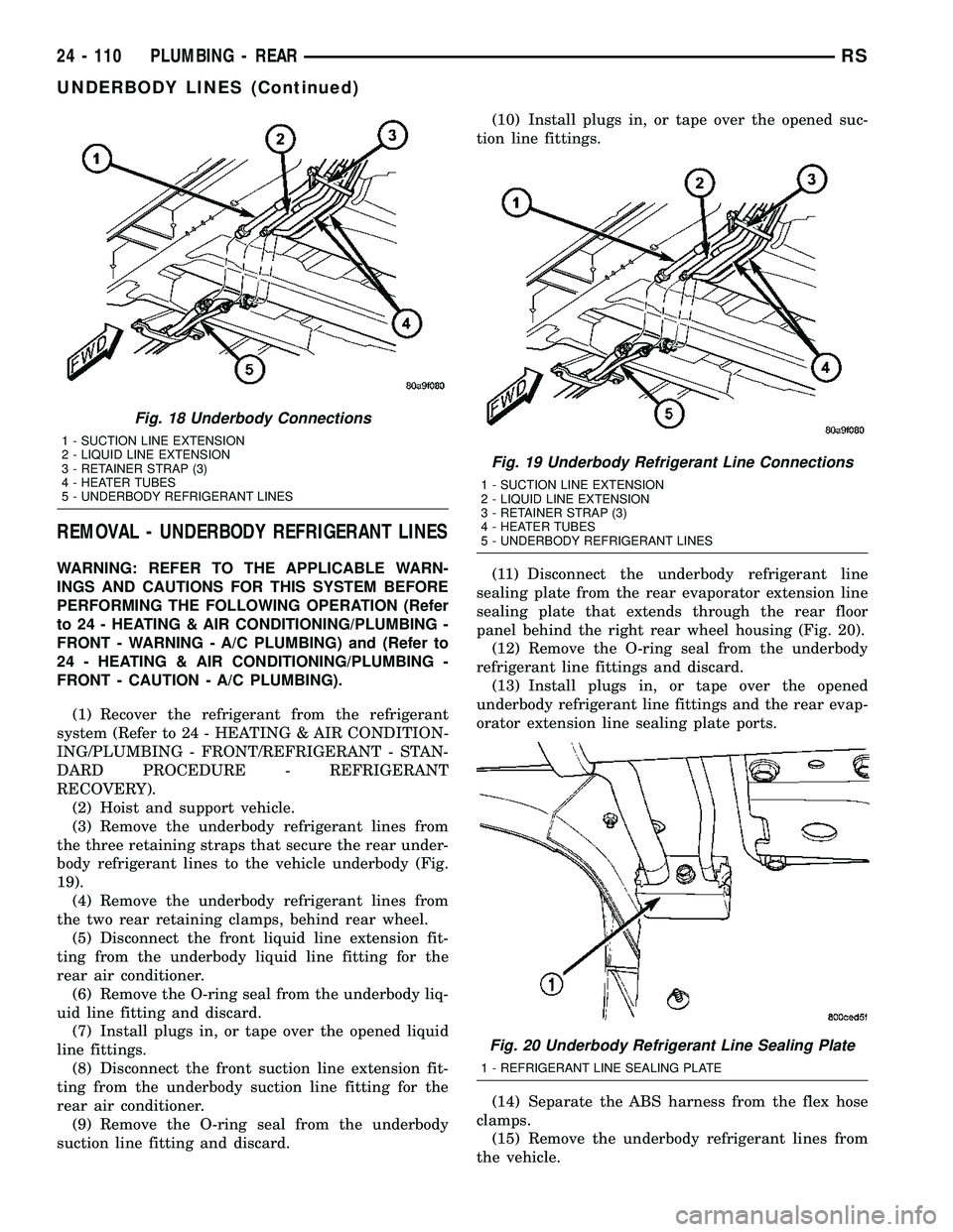
(3) Remove the underbody refrigerant lines from
the three retaining straps that secure the rear under-
body refrigerant lines to the vehicle underbody (Fig.
19).
(4) Remove the underbody refrigerant lines from
the two rear retaining clamps, behind rear wheel.
(5) Disconnect the front liquid line extension fit-
ting from the underbody liquid line fitting for the
rear air conditioner.
(6) Remove the O-ring seal from the underbody liq-
uid line fitting and discard.
(7) Install plugs in, or tape over the opened liquid
line fittings.
(8) Disconnect the front suction line extension fit-
ting from the underbody suction line fitting for the
rear air conditioner.
(9) Remove the O-ring seal from the underbody
suction line fitting and discard.(10) Install plugs in, or tape over the opened suc-
tion line fittings.
(11) Disconnect the underbody refrigerant line
sealing plate from the rear evaporator extension line
sealing plate that extends through the rear floor
panel behind the right rear wheel housing (Fig. 20).
(12) Remove the O-ring seal from the underbody
refrigerant line fittings and discard.
(13) Install plugs in, or tape over the opened
underbody refrigerant line fittings and the rear evap-
orator extension line sealing plate ports.
(14) Separate the ABS harness from the flex hose
clamps.
(15) Remove the underbody refrigerant lines from
the vehicle.
Fig. 18 Underbody Connections
1 - SUCTION LINE EXTENSION
2 - LIQUID LINE EXTENSION
3 - RETAINER STRAP (3)
4 - HEATER TUBES
5 - UNDERBODY REFRIGERANT LINES
Fig. 19 Underbody Refrigerant Line Connections
1 - SUCTION LINE EXTENSION
2 - LIQUID LINE EXTENSION
3 - RETAINER STRAP (3)
4 - HEATER TUBES
5 - UNDERBODY REFRIGERANT LINES
Fig. 20 Underbody Refrigerant Line Sealing Plate
1 - REFRIGERANT LINE SEALING PLATE
24 - 110 PLUMBING - REARRS
UNDERBODY LINES (Continued)
Page 2506 of 2585
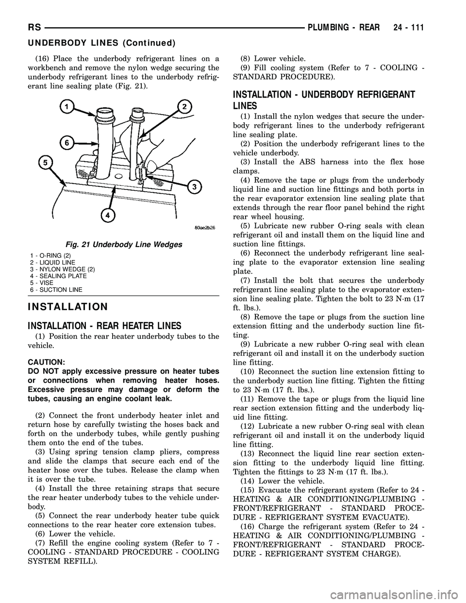
(16) Place the underbody refrigerant lines on a
workbench and remove the nylon wedge securing the
underbody refrigerant lines to the underbody refrig-
erant line sealing plate (Fig. 21).
INSTALLATION
INSTALLATION - REAR HEATER LINES
(1) Position the rear heater underbody tubes to the
vehicle.
CAUTION:
DO NOT apply excessive pressure on heater tubes
or connections when removing heater hoses.
Excessive pressure may damage or deform the
tubes, causing an engine coolant leak.
(2) Connect the front underbody heater inlet and
return hose by carefully twisting the hoses back and
forth on the underbody tubes, while gently pushing
them onto the end of the tubes.
(3) Using spring tension clamp pliers, compress
and slide the clamps that secure each end of the
heater hose over the tubes. Release the clamp when
it is over the tube.
(4) Install the three retaining straps that secure
the rear heater underbody tubes to the vehicle under-
body.
(5) Connect the rear underbody heater tube quick
connections to the rear heater core extension tubes.
(6) Lower the vehicle.
(7) Refill the engine cooling system (Refer to 7 -
COOLING - STANDARD PROCEDURE - COOLING
SYSTEM REFILL).(8) Lower vehicle.
(9) Fill cooling system (Refer to 7 - COOLING -
STANDARD PROCEDURE).
INSTALLATION - UNDERBODY REFRIGERANT
LINES
(1) Install the nylon wedges that secure the under-
body refrigerant lines to the underbody refrigerant
line sealing plate.
(2) Position the underbody refrigerant lines to the
vehicle underbody.
(3) Install the ABS harness into the flex hose
clamps.
(4) Remove the tape or plugs from the underbody
liquid line and suction line fittings and both ports in
the rear evaporator extension line sealing plate that
extends through the rear floor panel behind the right
rear wheel housing.
(5) Lubricate new rubber O-ring seals with clean
refrigerant oil and install them on the liquid line and
suction line fittings.
(6) Reconnect the underbody refrigerant line seal-
ing plate to the evaporator extension line sealing
plate.
(7) Install the bolt that secures the underbody
refrigerant line sealing plate to the evaporator exten-
sion line sealing plate. Tighten the bolt to 23 N´m (17
ft. lbs.).
(8) Remove the tape or plugs from the suction line
extension fitting and the underbody suction line fit-
ting.
(9) Lubricate a new rubber O-ring seal with clean
refrigerant oil and install it on the underbody suction
line fitting.
(10) Reconnect the suction line extension fitting to
the underbody suction line fitting. Tighten the fitting
to 23 N´m (17 ft. lbs.).
(11) Remove the tape or plugs from the liquid line
rear section extension fitting and the underbody liq-
uid line fitting.
(12) Lubricate a new rubber O-ring seal with clean
refrigerant oil and install it on the underbody liquid
line fitting.
(13) Reconnect the liquid line rear section exten-
sion fitting to the underbody liquid line fitting.
Tighten the fittings to 23 N´m (17 ft. lbs.).
(14) Lower the vehicle.
(15) Evacuate the refrigerant system (Refer to 24 -
HEATING & AIR CONDITIONING/PLUMBING -
FRONT/REFRIGERANT - STANDARD PROCE-
DURE - REFRIGERANT SYSTEM EVACUATE).
(16) Charge the refrigerant system (Refer to 24 -
HEATING & AIR CONDITIONING/PLUMBING -
FRONT/REFRIGERANT - STANDARD PROCE-
DURE - REFRIGERANT SYSTEM CHARGE).
Fig. 21 Underbody Line Wedges
1 - O-RING (2)
2 - LIQUID LINE
3 - NYLON WEDGE (2)
4 - SEALING PLATE
5 - VISE
6 - SUCTION LINE
RSPLUMBING - REAR24 - 111
UNDERBODY LINES (Continued)
Page 2507 of 2585
CABIN HEATER
TABLE OF CONTENTS
page page
CABIN HEATER
DESCRIPTION........................112
OPERATION
OPERATION - MANUAL TEMPERATURE
CONTROL SYSTEM...................112
OPERATION - AUTOMATIC TEMPERATURE
CONTROL SYSTEM...................112
DIAGNOSIS AND TESTING - DIESEL
SUPPLEMENTAL CABIN HEATER........113
AIR INTAKE PIPE
REMOVAL............................113
INSTALLATION........................114
EXHAUST TUBE
REMOVAL............................114
INSTALLATION........................115FUEL DOSING PUMP
DESCRIPTION........................115
OPERATION..........................115
REMOVAL............................115
INSTALLATION........................116
FUEL LINE
STANDARD PROCEDURE - CLEANING.....117
REMOVAL............................117
INSTALLATION........................118
HEATER UNIT
REMOVAL............................118
INSTALLATION........................119
SUPPLEMENTAL DIESEL HEATER WIRING
REMOVAL............................119
INSTALLATION........................119
CABIN HEATER
DESCRIPTION
Vehicles equipped with the diesel engine are also
equipped with a supplemental cabin heater. This
cabin heater is mounted under the vehicle and oper-
ates similar to an oil fired furnace. The heater burns
small amounts of fuel to provide additional heat to
the coolant. Coolant is routed from the engine, to the
supplemental cabin heater and then to the front
heater core. This provides additional heat to the pas-
senger compartment. The supplemental cabin heater
system is interfaced to the vehicles on-board com-
puter systems and DRBIIItdiagnostics.
The supplemental cabin heater has an electronic
control module that monitors the heat output of the
heater. The cabin heater operates at full load (5 kW),
half load or idle mode (no additional heat) depending
on engine coolant temperature.
OPERATION
OPERATION - MANUAL TEMPERATURE
CONTROL SYSTEM
The supplemental cabin heater is activated via the
temperature slide control or knob on the A/C-heater
control when equipped with the manual temperature
control (MTC) system. If the slide control or knob is
moved to or above the upper set point the cabin
heater is activated. The cabin heater can operate in a
full or partial load range as well as an idle mode alldependent on the engine coolant temperature. The
cabin heater will also turn off if the A/C-heater tem-
perature control is lowered to less than the lower set
point. The cabin heater can take up to three minutes
to completely shut down when either the heater tem-
perature is set below the lower set point or the vehi-
cle ignition is shut down.
NOTE: Do not apply a strong vacuum source such
as a garage ventilation system directly on the sup-
plemental cabin heater exhaust line. Too strong of a
vacuum can prevent the supplemental cabin heater
from starting. If required, place the vacuum source
at least 75 mm (3 in.) away from the exhaust line.
The supplemental cabin heater only operates when
the engine is running, the mileage exceeds 8 kilome-
ter (5 mph) and the fuel tank volume exceeds 1/8 of a
tank. The supplemental heater control module moni-
tors blower speed and combustion during its start-up.
The cabin heater should operate if the coolant tem-
perature is below 40É C (104É F).
OPERATION - AUTOMATIC TEMPERATURE
CONTROL SYSTEM
The automatic temperature control (ATC) system
will activate the supplemental cabin heater based on
engine coolant temperature and interior component
settings. The cabin heater can operate in a full or
partial load range as well as an idle mode all depen-
dent on the engine coolant temperature. The cabin
heater will also turn off if the A/C-heater tempera-
ture control is lowered to less than the lower set
24 - 112 CABIN HEATERRS