2004 CHRYSLER VOYAGER transmission fluid
[x] Cancel search: transmission fluidPage 1846 of 2585
Since there are four switches, there are 16 possible
combinations of open and closed switches (codes).
Seven of these codes are related to gear position and
three are recognized as ªbetween gearº codes. This
results in six codes which should never occur. These
are called ªinvalidº codes. An invalid code will result
in a DTC, and the PCM/TCM will then determine the
shift lever position based on pressure switch data.
This allows reasonably normal transmission opera-
tion with a TRS failure.
TRS SWITCH STATES
SLP T42 T41 T3 T1
PCL CL CL OP
RCL OP OP OP
NCL CL OP CL
ODOP OP OP CL
3OP OP CL OP
LCL OP CL CL
TRANSMISSION TEMPERATURE SENSOR
The TRS has an integrated thermistor (Fig. 329)
that the PCM/TCM uses to monitor the transmis-
sion's sump temperature. Since fluid temperature
can affect transmission shift quality and convertor
lock up, the PCM/TCM requires this information to
determine which shift schedule to operate in. The
PCM also monitors this temperature data so it can
energize the vehicle cooling fan(s) when a transmis-
sion ªoverheatº condition exists. If the thermistor cir-
cuit fails, the PCM/TCM will revert to calculated oil
temperature usage.
CALCULATED TEMPERATURE
A failure in the temperature sensor or circuit will
result in calculated temperature being substituted for
actual temperature. Calculated temperature is a pre-
dicted fluid temperature which is calculated from a
combination of inputs:
²Battery (ambient) temperature
²Engine coolant temperature
²In-gear run time since start-up
REMOVAL
(1) Remove valve body assembly from transaxle.
(Refer to 21 - TRANSMISSION/TRANSAXLE/AUTO-
MATIC - 41TE/VALVE BODY - REMOVAL)
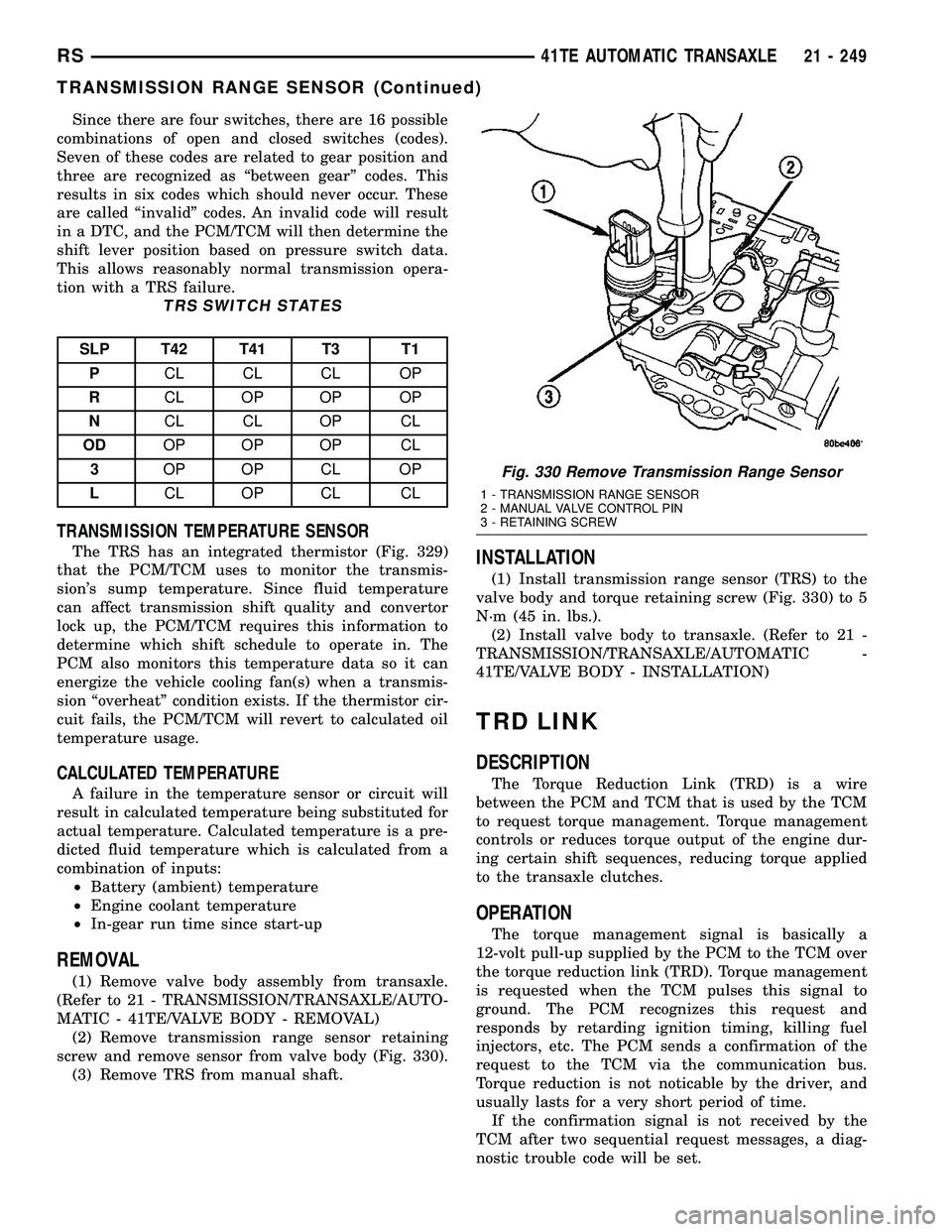
(2) Remove transmission range sensor retaining
screw and remove sensor from valve body (Fig. 330).
(3) Remove TRS from manual shaft.
INSTALLATION
(1) Install transmission range sensor (TRS) to the
valve body and torque retaining screw (Fig. 330) to 5
N´m (45 in. lbs.).
(2) Install valve body to transaxle. (Refer to 21 -
TRANSMISSION/TRANSAXLE/AUTOMATIC -
41TE/VALVE BODY - INSTALLATION)
TRD LINK
DESCRIPTION
The Torque Reduction Link (TRD) is a wire
between the PCM and TCM that is used by the TCM
to request torque management. Torque management
controls or reduces torque output of the engine dur-
ing certain shift sequences, reducing torque applied
to the transaxle clutches.
OPERATION
The torque management signal is basically a
12-volt pull-up supplied by the PCM to the TCM over
the torque reduction link (TRD). Torque management
is requested when the TCM pulses this signal to
ground. The PCM recognizes this request and
responds by retarding ignition timing, killing fuel
injectors, etc. The PCM sends a confirmation of the
request to the TCM via the communication bus.
Torque reduction is not noticable by the driver, and
usually lasts for a very short period of time.
If the confirmation signal is not received by the
TCM after two sequential request messages, a diag-
nostic trouble code will be set.
Fig. 330 Remove Transmission Range Sensor
1 - TRANSMISSION RANGE SENSOR
2 - MANUAL VALVE CONTROL PIN
3 - RETAINING SCREW
RS41TE AUTOMATIC TRANSAXLE21 - 249
TRANSMISSION RANGE SENSOR (Continued)
Page 1847 of 2585
VALVE BODY
DESCRIPTION
The valve body assembly consists of a cast alumi-
num valve body, a separator plate, and transfer
plate. The valve body contains valves and check balls
that control fluid delivery to the torque converter
clutch, solenoid/pressure switch assembly, and fric-
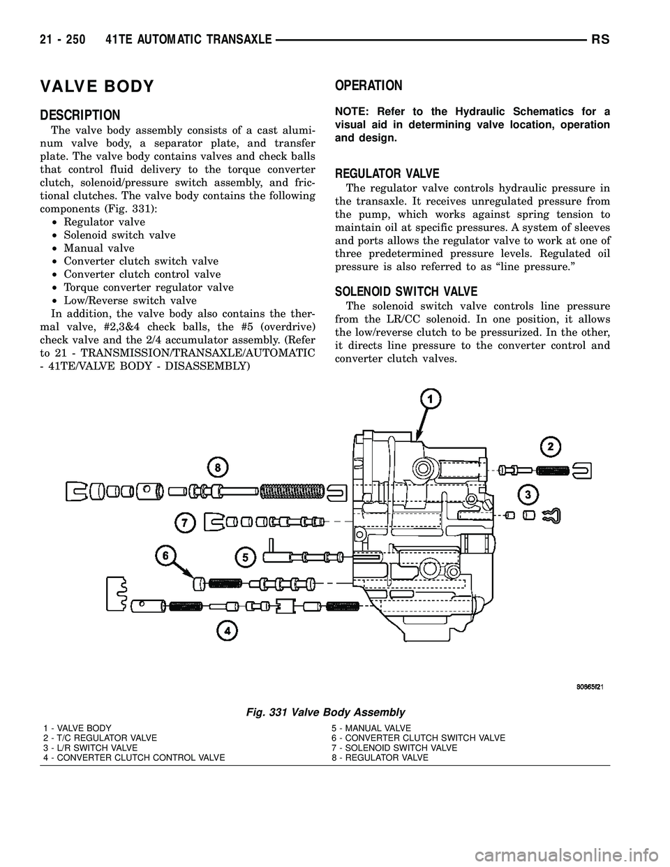
tional clutches. The valve body contains the following
components (Fig. 331):
²Regulator valve
²Solenoid switch valve
²Manual valve
²Converter clutch switch valve
²Converter clutch control valve
²Torque converter regulator valve
²Low/Reverse switch valve
In addition, the valve body also contains the ther-
mal valve, #2,3&4 check balls, the #5 (overdrive)
check valve and the 2/4 accumulator assembly. (Refer
to 21 - TRANSMISSION/TRANSAXLE/AUTOMATIC
- 41TE/VALVE BODY - DISASSEMBLY)
OPERATION
NOTE: Refer to the Hydraulic Schematics for a
visual aid in determining valve location, operation
and design.
REGULATOR VALVE
The regulator valve controls hydraulic pressure in
the transaxle. It receives unregulated pressure from
the pump, which works against spring tension to
maintain oil at specific pressures. A system of sleeves
and ports allows the regulator valve to work at one of
three predetermined pressure levels. Regulated oil
pressure is also referred to as ªline pressure.º
SOLENOID SWITCH VALVE
The solenoid switch valve controls line pressure
from the LR/CC solenoid. In one position, it allows
the low/reverse clutch to be pressurized. In the other,
it directs line pressure to the converter control and
converter clutch valves.
Fig. 331 Valve Body Assembly
1 - VALVE BODY 5 - MANUAL VALVE
2 - T/C REGULATOR VALVE 6 - CONVERTER CLUTCH SWITCH VALVE
3 - L/R SWITCH VALVE 7 - SOLENOID SWITCH VALVE
4 - CONVERTER CLUTCH CONTROL VALVE 8 - REGULATOR VALVE
21 - 250 41TE AUTOMATIC TRANSAXLERS
Page 1848 of 2585
MANUAL VALVE
The manual valve is operated by the mechanical
shift linkage. Its primary responsibility is to send
line pressure to the appropriate hydraulic circuits
and solenoids. The valve has three operating ranges
or positions.
CONVERTER CLUTCH SWITCH VALVE
The main responsibility of the converter clutch
switch valve is to control hydraulic pressure applied
to the front (off) side of the converter clutch piston.
Line pressure from the regulator valve is fed to the
torque converter regulator valve, where it passes
through the valve, and is slightly regulated. The
pressure is then directed to the converter clutch
switch valve and to the front side of the converter
clutch piston. This pressure pushes the piston back
and disengages the converter clutch.
CONVERTER CLUTCH CONTROL VALVE
The converter clutch control valve controls the
back (on) side of the torque converter clutch. When
the PCM/TCM energizes or modulates the LR/CC
solenoid to apply the converter clutch piston, both
the converter clutch control valve and the converter
control valve move, allowing pressure to be applied to
the back side of the clutch.
T/C REGULATOR VALVE
The torque converter regulator valve slightly regu-
lates the flow of fluid to the torque converter.
LOW/REVERSE SWITCH VALVE
The low/reverse clutch is applied from different
sources, depending on whether low (1st) gear or
reverse is selected. The low/reverse switch valve
alternates positions depending on from which direc-
tion fluid pressure is applied. By design, when the
valve is shifted by fluid pressure from one channel,
the opposing channel is blocked. The switch valve
alienates the possibility of a sticking ball check, thus
providing consistent application of the low/reverse
clutch under all operating conditions.
REMOVAL
NOTE: If valve body is replaced or reconditioned,
the TCM Quick Learn Procedure must be per-
formed. (Refer to 8 - ELECTRICAL/ELECTRONIC
CONTROL MODULES/TRANSMISSION CONTROL
MODULE - STANDARD PROCEDURE)(1) Disconnect battery negative cable.
(2) Disconnect gearshift cable from manual valve
lever.
(3) Remove manual valve lever from manual shaft.
(4) Raise vehicle on hoist.
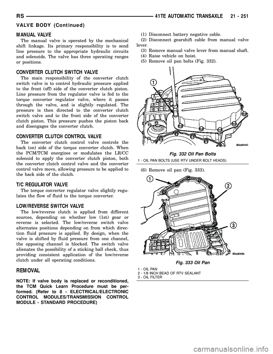
(5) Remove oil pan bolts (Fig. 332).
(6) Remove oil pan (Fig. 333).
Fig. 332 Oil Pan Bolts
1 - OIL PAN BOLTS (USE RTV UNDER BOLT HEADS)
Fig. 333 Oil Pan
1 - OIL PAN
2 - 1/8 INCH BEAD OF RTV SEALANT
3 - OIL FILTER
RS41TE AUTOMATIC TRANSAXLE21 - 251
VALVE BODY (Continued)
Page 1860 of 2585
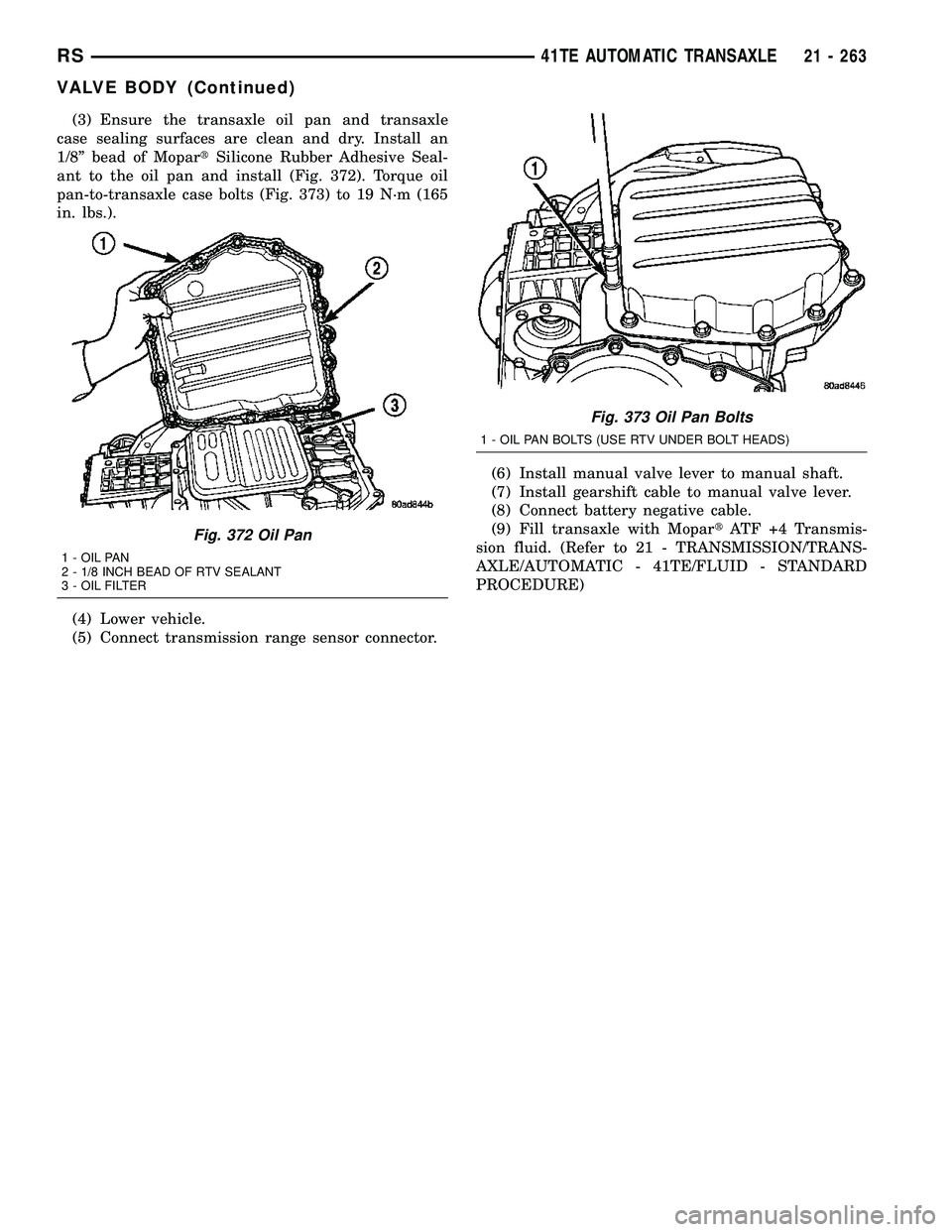
(3) Ensure the transaxle oil pan and transaxle
case sealing surfaces are clean and dry. Install an
1/8º bead of MopartSilicone Rubber Adhesive Seal-
ant to the oil pan and install (Fig. 372). Torque oil
pan-to-transaxle case bolts (Fig. 373) to 19 N´m (165
in. lbs.).
(4) Lower vehicle.
(5) Connect transmission range sensor connector.(6) Install manual valve lever to manual shaft.
(7) Install gearshift cable to manual valve lever.
(8) Connect battery negative cable.
(9) Fill transaxle with MopartATF +4 Transmis-
sion fluid. (Refer to 21 - TRANSMISSION/TRANS-
AXLE/AUTOMATIC - 41TE/FLUID - STANDARD
PROCEDURE)
Fig. 372 Oil Pan
1 - OIL PAN
2 - 1/8 INCH BEAD OF RTV SEALANT
3 - OIL FILTER
Fig. 373 Oil Pan Bolts
1 - OIL PAN BOLTS (USE RTV UNDER BOLT HEADS)
RS41TE AUTOMATIC TRANSAXLE21 - 263
VALVE BODY (Continued)
Page 1885 of 2585
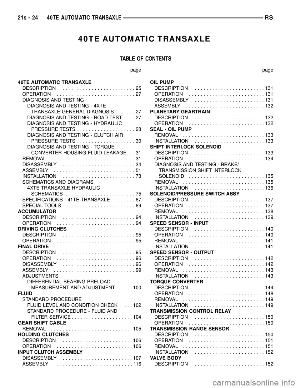
40TE AUTOMATIC TRANSAXLE
TABLE OF CONTENTS
page page
40TE AUTOMATIC TRANSAXLE DESCRIPTION .........................25
OPERATION ...........................27
DIAGNOSIS AND TESTING DIAGNOSIS AND TESTING - 4XTETRANSAXLE GENERAL DIAGNOSIS .......27
DIAGNOSIS AND TESTING - ROAD TEST . . . 27
DIAGNOSIS AND TESTING - HYDRAULIC PRESSURE TESTS ....................28
DIAGNOSIS AND TESTING - CLUTCH AIR PRESSURE TESTS ....................30
DIAGNOSIS AND TESTING - TORQUE CONVERTER HOUSING FLUID LEAKAGE . . . 31
REMOVAL .............................31
DISASSEMBLY .........................34
ASSEMBLY ............................51
INSTALLATION .........................73
SCHEMATICS AND DIAGRAMS 4XTE TRANSAXLE HYDRAULICSCHEMATICS ........................75
SPECIFICATIONS - 41TE TRANSAXLE .......87
SPECIAL TOOLS .......................89
ACCUMULATOR DESCRIPTION .........................94
OPERATION ...........................94
DRIVING CLUTCHES DESCRIPTION .........................95
OPERATION ...........................95
FINAL DRIVE DESCRIPTION .........................95
OPERATION ...........................96
DISASSEMBLY .........................96
ASSEMBLY ............................99
ADJUSTMENTS DIFFERENTIAL BEARING PRELOADMEASUREMENT AND ADJUSTMENT ......100
FLUID STANDARD PROCEDURE FLUID LEVEL AND CONDITION CHECK . . . 102
STANDARD PROCEDURE - FLUID ANDFILTER SERVICE .....................104
GEAR SHIFT CABLE REMOVAL ............................105
HOLDING CLUTCHES DESCRIPTION ........................106
OPERATION ..........................106
INPUT CLUTCH ASSEMBLY DISASSEMBLY ........................107
ASSEMBLY ...........................116 OIL PUMP
DESCRIPTION ........................131
OPERATION ..........................131
DISASSEMBLY ........................131
ASSEMBLY ...........................132
PLANETARY GEARTRAIN DESCRIPTION ........................132
OPERATION ..........................132
SEAL - OIL PUMP REMOVAL ............................133
INSTALLATION ........................133
SHIFT INTERLOCK SOLENOID DESCRIPTION ........................133
OPERATION ..........................134
DIAGNOSIS AND TESTING - BRAKE/ TRANSMISSION SHIFT INTERLOCK
SOLENOID ..........................135
REMOVAL ............................135
INSTALLATION ........................136
SOLENOID/PRESSURE SWITCH ASSY DESCRIPTION ........................137
OPERATION ..........................137
REMOVAL ............................138
INSTALLATION ........................139
SPEED SENSOR - INPUT DESCRIPTION ........................140
OPERATION ..........................140
REMOVAL ............................141
INSTALLATION ........................141
SPEED SENSOR - OUTPUT DESCRIPTION ........................142
OPERATION ..........................142
REMOVAL ............................143
INSTALLATION ........................143
TORQUE CONVERTER DESCRIPTION ........................144
OPERATION ..........................148
REMOVAL ............................149
INSTALLATION ........................149
TRANSMISSION CONTROL RELAY DESCRIPTION ........................150
OPERATION ..........................150
TRANSMISSION RANGE SENSOR DESCRIPTION ........................150
OPERATION ..........................151
REMOVAL ............................151
INSTALLATION ........................152
VALVE BODY DESCRIPTION ........................152
21s - 24 40TE AUTOMATIC TRANSAXLERS
Page 1888 of 2585
OPERATION
Transmission output is directed to an integral dif-
ferential by a transfer gear system in the following
input-to-output ratios:
First ............................... 2.84 : 1
Second ............................. 1.57 : 1
Third .............................. 1.00 : 1
Overdrive ........................... 0.69 : 1
Reverse ............................ 2.21 : 1
DIAGNOSIS AND TESTING
DIAGNOSIS AND TESTING - 4XTE TRANSAXLE
GENERAL DIAGNOSIS
NOTE: Before attempting any repair on a 4XTE four-
speed automatic transaxle, check for diagnostic trou-
ble codes (DTC's) using the DRB scan tool. Refer to
the Transmission Diagnostic Procedures Manual.
Transaxle malfunctions may be caused by these
general conditions: ² Poor engine performance
² Improper adjustments
² Hydraulic malfunctions
² Mechanical malfunctions
² Electronic malfunctions
Diagnosis of these problems should always begin by
checking the easily accessible variables: fluid level and
condition, gearshift cable adjustment. Then perform a
road test to determine if the problem has been corrected
or that more diagnosis is necessary. If the problem per-
sists after the preliminary tests and corrections are com-
pleted, hydraulic pressure checks should be performed.
DIAGNOSIS AND TESTING - ROAD TEST
Prior to performing a road test, verify that the
fluid level, fluid condition, and linkage adjustment
have been approved. During the road test, the transaxle should be oper-
ated in each position to check for slipping and any
variation in shifting. If the vehicle operates properly at highway speeds,
but has poor acceleration, the converter stator over-
running clutch may be slipping. If acceleration is nor-
mal, but high throttle opening is needed to maintain
highway speeds, the converter stator clutch may
have seized. Both of these stator defects require
replacement of the torque converter and thorough
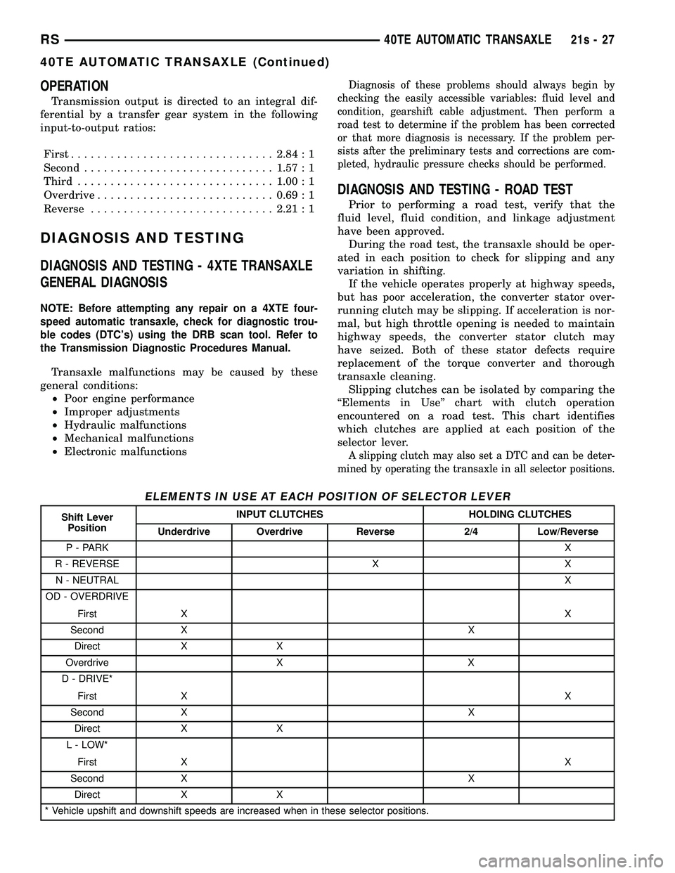
transaxle cleaning. Slipping clutches can be isolated by comparing the
ªElements in Useº chart with clutch operation
encountered on a road test. This chart identifies
which clutches are applied at each position of the
selector lever.
A slipping clutch may also set a DTC and can be deter-
mined by operating the transaxle in all selector positions.
ELEMENTS IN USE AT EACH POSITION OF SELECTOR LEVER
Shift Lever Position INPUT CLUTCHES HOLDING CLUTCHES
Underdrive Overdrive Reverse 2/4 Low/Reverse
P - PARK X
R - REVERSE X X N - NEUTRAL X
OD - OVERDRIVE
First X X
Second X X Direct X X
Overdrive X X
D - DRIVE*
First X X
Second X X Direct X X
L - LOW*
First X X
Second X X
Direct X X
* Vehicle upshift and downshift speeds are increased when in these selector positions.
RS 40TE AUTOMATIC TRANSAXLE21s-27
40TE AUTOMATIC TRANSAXLE (Continued)
Page 1892 of 2585
DIAGNOSIS AND TESTING - TORQUE
CONVERTER HOUSING FLUID LEAKAGE
When diagnosing converter housing fluid leaks,
three actions must be taken before repair: (1) Verify proper transmission fluid level.
(2) Verify that the leak originates from the con-
verter housing area and is transmission fluid. (3) Determine the true source of the leak.
Fluid leakage at or around the torque converter
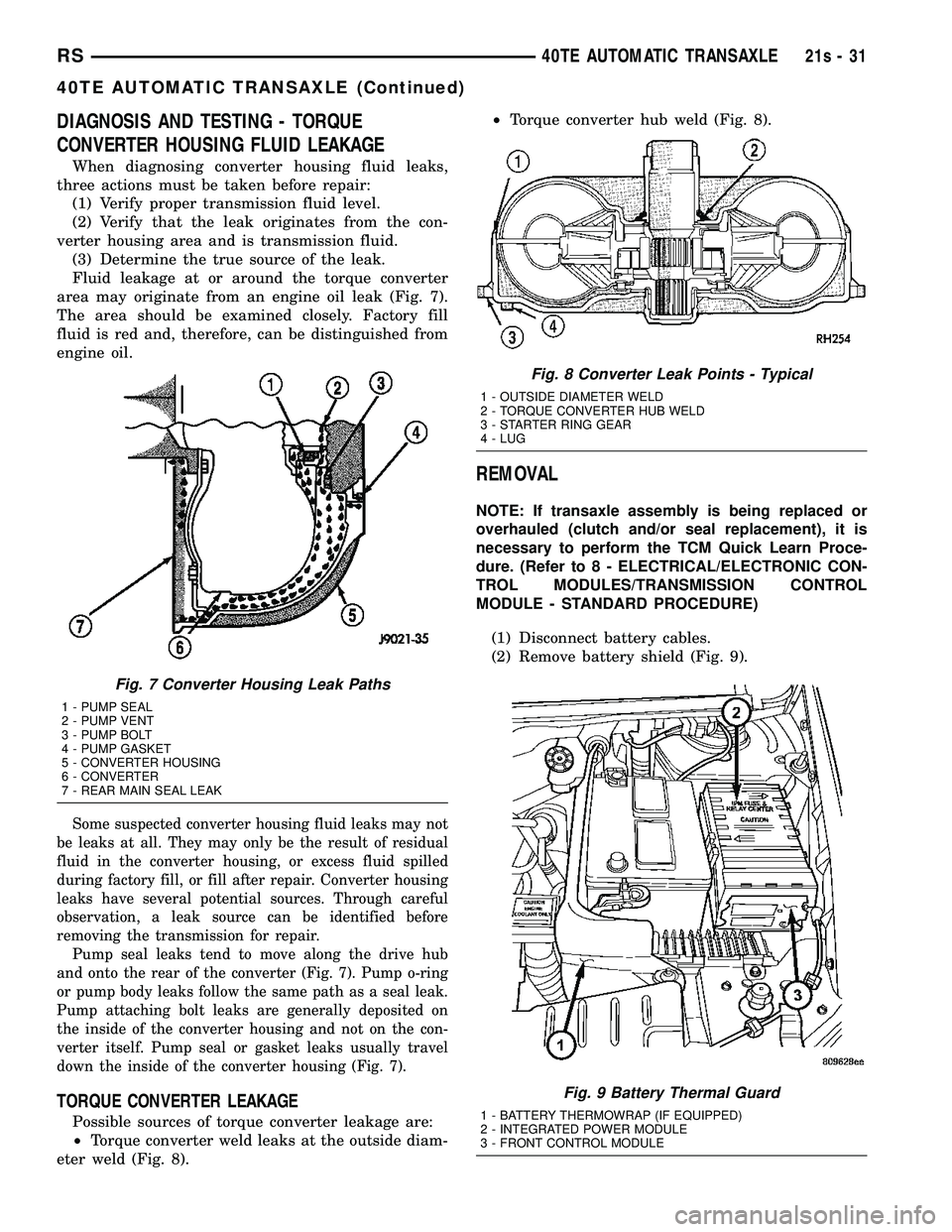
area may originate from an engine oil leak (Fig. 7).
The area should be examined closely. Factory fill
fluid is red and, therefore, can be distinguished from
engine oil.
Some suspected converter housing fluid leaks may not
be leaks at all. They may only be the result of residual
fluid in the converter housing, or excess fluid spilled
during factory fill, or fill after repair. Converter housing
leaks have several potential sources. Through careful
observation, a leak source can be identified before
removing the transmission for repair. Pump seal leaks tend to move along the drive hub
and onto the rear of the converter (Fig. 7). Pump o-ring
or pump body leaks follow the same path as a seal leak.
Pump attaching bolt leaks are generally deposited on
the inside of the converter housing and not on the con-
verter itself. Pump seal or gasket leaks usually travel
down the inside of the converter housing (Fig. 7).
TORQUE CONVERTER LEAKAGE
Possible sources of torque converter leakage are:
² Torque converter weld leaks at the outside diam-
eter weld (Fig. 8). ²
Torque converter hub weld (Fig. 8).
REMOVAL
NOTE: If transaxle assembly is being replaced or
overhauled (clutch and/or seal replacement), it is
necessary to perform the TCM Quick Learn Proce-
dure. (Refer t o 8 - ELECTRICAL/ELECTRONIC CON-
TROL MODULES/TRANSMISSION CONTROL
MODULE - STANDARD PROCEDURE)
(1) Disconnect battery cables.
(2) Remove battery shield (Fig. 9).
Fig. 7 Converter Housing Leak Paths
1 - PUMP SEAL
2 - PUMP VENT
3 - PUMP BOLT
4 - PUMP GASKET
5 - CONVERTER HOUSING
6 - CONVERTER
7 - REAR MAIN SEAL LEAK
Fig. 8 Converter Leak Points - Typical
1 - OUTSIDE DIAMETER WELD
2 - TORQUE CONVERTER HUB WELD
3 - STARTER RING GEAR
4 - LUG
Fig. 9 Battery Thermal Guard
1 - BATTERY THERMOWRAP (IF EQUIPPED)
2 - INTEGRATED POWER MODULE
3 - FRONT CONTROL MODULE
RS 40TE AUTOMATIC TRANSAXLE21s-31
40TE AUTOMATIC TRANSAXLE (Continued)
Page 1893 of 2585
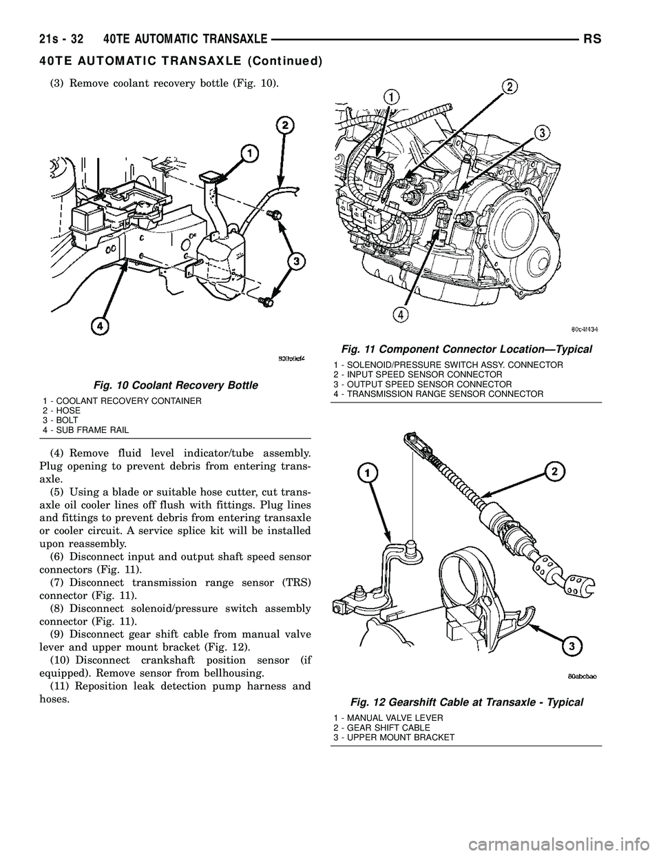
(3) Remove coolant recovery bottle (Fig. 10).
(4) Remove fluid level indicator/tube assembly.
Plug opening to prevent debris from entering trans-
axle. (5) Using a blade or suitable hose cutter, cut trans-
axle oil cooler lines off flush with fittings. Plug lines
and fittings to prevent debris from entering transaxle
or cooler circuit. A service splice kit will be installed
upon reassembly. (6) Disconnect input and output shaft speed sensor
connectors (Fig. 11). (7) Disconnect transmission range sensor (TRS)
connector (Fig. 11). (8) Disconnect solenoid/pressure switch assembly
connector (Fig. 11). (9) Disconnect gear shift cable from manual valve
lever and upper mount bracket (Fig. 12). (10) Disconnect crankshaft position sensor (if
equipped). Remove sensor from bellhousing. (11) Reposition leak detection pump harness and
hoses.
Fig. 10 Coolant Recovery Bottle
1 - COOLANT RECOVERY CONTAINER
2 - HOSE
3 - BOLT
4 - SUB FRAME RAIL
Fig. 11 Component Connector LocationÐTypical
1 - SOLENOID/PRESSURE SWITCH ASSY. CONNECTOR
2 - INPUT SPEED SENSOR CONNECTOR
3 - OUTPUT SPEED SENSOR CONNECTOR
4 - TRANSMISSION RANGE SENSOR CONNECTOR
Fig. 12 Gearshift Cable at Transaxle - Typical
1 - MANUAL VALVE LEVER
2 - GEAR SHIFT CABLE
3 - UPPER MOUNT BRACKET
21s - 32 40TE AUTOMATIC TRANSAXLERS
40TE AUTOMATIC TRANSAXLE (Continued)