2004 CHRYSLER VOYAGER transmission fluid
[x] Cancel search: transmission fluidPage 1589 of 2585
FLUID
STANDARD PROCEDURE - POWER STEERING
FLUID LEVEL CHECKING
WARNING: FLUID LEVEL SHOULD BE CHECKED
WITH THE ENGINE OFF TO PREVENT INJURY
FROM MOVING PARTS AND TO ENSURE ACCU-
RATE FLUID LEVEL READING.
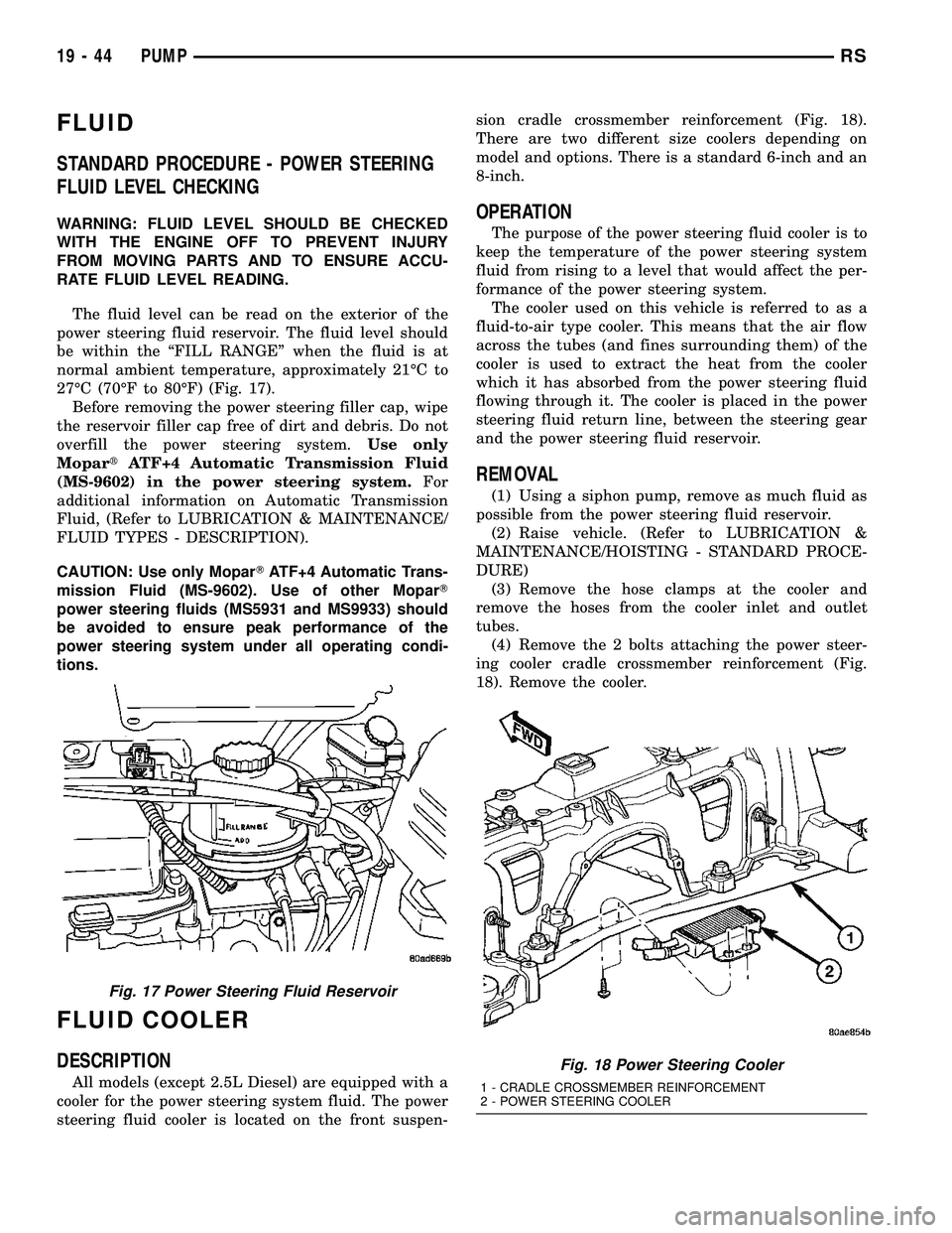
The fluid level can be read on the exterior of the
power steering fluid reservoir. The fluid level should
be within the ªFILL RANGEº when the fluid is at
normal ambient temperature, approximately 21ÉC to
27ÉC (70ÉF to 80ÉF) (Fig. 17).
Before removing the power steering filler cap, wipe
the reservoir filler cap free of dirt and debris. Do not
overfill the power steering system.Use only
MopartATF+4 Automatic Transmission Fluid
(MS-9602) in the power steering system.For
additional information on Automatic Transmission
Fluid, (Refer to LUBRICATION & MAINTENANCE/
FLUID TYPES - DESCRIPTION).
CAUTION: Use only MoparTATF+4 Automatic Trans-
mission Fluid (MS-9602). Use of other MoparT
power steering fluids (MS5931 and MS9933) should
be avoided to ensure peak performance of the
power steering system under all operating condi-
tions.
FLUID COOLER
DESCRIPTION
All models (except 2.5L Diesel) are equipped with a
cooler for the power steering system fluid. The power
steering fluid cooler is located on the front suspen-sion cradle crossmember reinforcement (Fig. 18).
There are two different size coolers depending on
model and options. There is a standard 6-inch and an
8-inch.
OPERATION
The purpose of the power steering fluid cooler is to
keep the temperature of the power steering system
fluid from rising to a level that would affect the per-
formance of the power steering system.
The cooler used on this vehicle is referred to as a
fluid-to-air type cooler. This means that the air flow
across the tubes (and fines surrounding them) of the
cooler is used to extract the heat from the cooler
which it has absorbed from the power steering fluid
flowing through it. The cooler is placed in the power
steering fluid return line, between the steering gear
and the power steering fluid reservoir.
REMOVAL
(1) Using a siphon pump, remove as much fluid as
possible from the power steering fluid reservoir.
(2) Raise vehicle. (Refer to LUBRICATION &
MAINTENANCE/HOISTING - STANDARD PROCE-
DURE)
(3) Remove the hose clamps at the cooler and
remove the hoses from the cooler inlet and outlet
tubes.
(4) Remove the 2 bolts attaching the power steer-
ing cooler cradle crossmember reinforcement (Fig.
18). Remove the cooler.
Fig. 17 Power Steering Fluid Reservoir
Fig. 18 Power Steering Cooler
1 - CRADLE CROSSMEMBER REINFORCEMENT
2 - POWER STEERING COOLER
19 - 44 PUMPRS
Page 1598 of 2585
TRANSMISSION/TRANSAXLE
TABLE OF CONTENTS
page page
POWER TRANSFER UNIT..................1
T850 MANUAL TRANSAXLE...............2141TE AUTOMATIC TRANSAXLE............116
POWER TRANSFER UNIT
TABLE OF CONTENTS
page page
POWER TRANSFER UNIT
DESCRIPTION..........................1
OPERATION............................3
DIAGNOSIS AND TESTING
SEAL IDENTIFICATION..................3
FLUID LEAK DIAGNOSIS................3
STANDARD PROCEDURE
STANDARD PROCEDURE - FLUID LEVEL
INSPECTION..........................4
STANDARD PROCEDURE - PTU FLUID
CHANGE.............................5
REMOVAL.............................5
INSTALLATION..........................6
ADJUSTMENTS
OUTPUT FLANGE SHIM SELECTION.......7
SPECIFICATIONS
TORQUE.............................7
SPECIAL TOOLS
SDP POWER TRANSFER UNIT............8
DIFFERENTIAL CARRIER SEAL
REMOVAL.............................9
INSTALLATION..........................9
END COVER BALL BEARING
REMOVAL.............................9INSTALLATION.........................10
END COVER SEAL
REMOVAL.............................11
INSTALLATION.........................11
HALF SHAFT INNER SEAL
REMOVAL.............................12
INSTALLATION.........................12
INPUT SHAFT COVER SEAL
REMOVAL.............................13
INSTALLATION.........................14
INPUT SHAFT END SEAL
REMOVAL.............................15
INSTALLATION.........................16
INPUT SHAFT SEAL
REMOVAL.............................17
INSTALLATION.........................18
OUTER HALF SHAFT SEAL
REMOVAL.............................19
INSTALLATION.........................19
REAR COVER O-RING
REMOVAL.............................19
INSTALLATION.........................20
POWER TRANSFER UNIT
DESCRIPTION
The Power Transfer Unit (P.T.U.) is attached to a
modified automatic transaxle case where the right
half shaft extension housing would normally be
located.
The Power Transfer Unit is sealed from the trans-
axle and has its own oil sump. The Unit uses MopartSAE 80W-90 Gear and Axle Lubricant (MS-9020) and
holds 1.15 liters (1.22 quarts).
Service of the Power Transfer Unit is limited to:
²Fluid Change
²Seals
²Gaskets
²One ball bearing
²Output flange
If the ring gear and pinion, any tapered roller
bearings, case, covers, or pinion carrier fail the entire
unit must be replaced.
RSTRANSMISSION/TRANSAXLE21-1
Page 1600 of 2585
OPERATION
The Transfer Unit provides the power to the rear
wheels through a hypoid ring gear and pinion set.
DIAGNOSIS AND TESTING
SEAL IDENTIFICATION
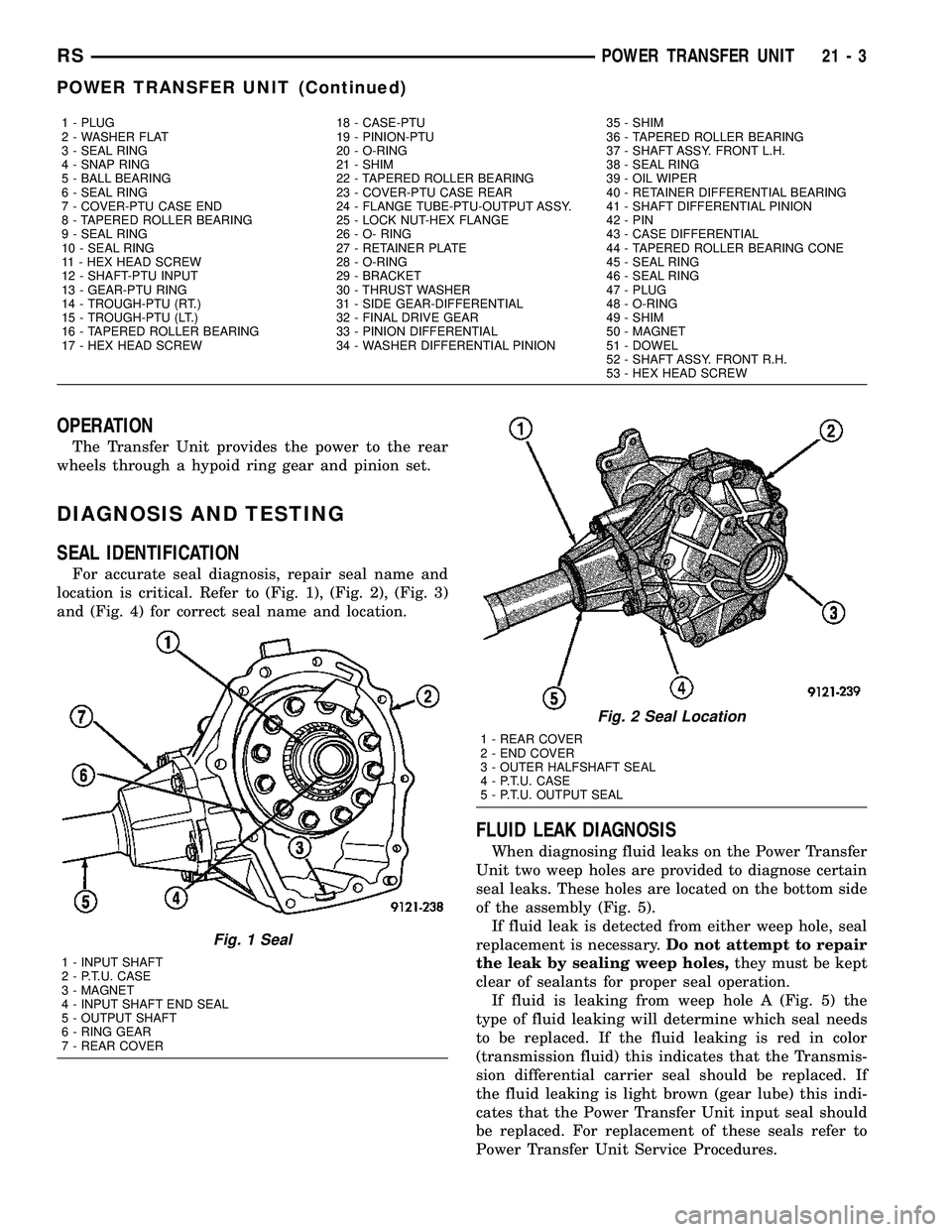
For accurate seal diagnosis, repair seal name and
location is critical. Refer to (Fig. 1), (Fig. 2), (Fig. 3)
and (Fig. 4) for correct seal name and location.
FLUID LEAK DIAGNOSIS
When diagnosing fluid leaks on the Power Transfer
Unit two weep holes are provided to diagnose certain
seal leaks. These holes are located on the bottom side
of the assembly (Fig. 5).
If fluid leak is detected from either weep hole, seal
replacement is necessary.Do not attempt to repair
the leak by sealing weep holes,they must be kept
clear of sealants for proper seal operation.
If fluid is leaking from weep hole A (Fig. 5) the
type of fluid leaking will determine which seal needs
to be replaced. If the fluid leaking is red in color
(transmission fluid) this indicates that the Transmis-
sion differential carrier seal should be replaced. If
the fluid leaking is light brown (gear lube) this indi-
cates that the Power Transfer Unit input seal should
be replaced. For replacement of these seals refer to
Power Transfer Unit Service Procedures.
1 - PLUG 18 - CASE-PTU 35 - SHIM
2 - WASHER FLAT 19 - PINION-PTU 36 - TAPERED ROLLER BEARING
3 - SEAL RING 20 - O-RING 37 - SHAFT ASSY. FRONT L.H.
4 - SNAP RING 21 - SHIM 38 - SEAL RING
5 - BALL BEARING 22 - TAPERED ROLLER BEARING 39 - OIL WIPER
6 - SEAL RING 23 - COVER-PTU CASE REAR 40 - RETAINER DIFFERENTIAL BEARING
7 - COVER-PTU CASE END 24 - FLANGE TUBE-PTU-OUTPUT ASSY. 41 - SHAFT DIFFERENTIAL PINION
8 - TAPERED ROLLER BEARING 25 - LOCK NUT-HEX FLANGE 42 - PIN
9 - SEAL RING 26 - O- RING 43 - CASE DIFFERENTIAL
10 - SEAL RING 27 - RETAINER PLATE 44 - TAPERED ROLLER BEARING CONE
11 - HEX HEAD SCREW 28 - O-RING 45 - SEAL RING
12 - SHAFT-PTU INPUT 29 - BRACKET 46 - SEAL RING
13 - GEAR-PTU RING 30 - THRUST WASHER 47 - PLUG
14 - TROUGH-PTU (RT.) 31 - SIDE GEAR-DIFFERENTIAL 48 - O-RING
15 - TROUGH-PTU (LT.) 32 - FINAL DRIVE GEAR 49 - SHIM
16 - TAPERED ROLLER BEARING 33 - PINION DIFFERENTIAL 50 - MAGNET
17 - HEX HEAD SCREW 34 - WASHER DIFFERENTIAL PINION 51 - DOWEL
52 - SHAFT ASSY. FRONT R.H.
53 - HEX HEAD SCREW
Fig. 1 Seal
1 - INPUT SHAFT
2 - P.T.U. CASE
3 - MAGNET
4 - INPUT SHAFT END SEAL
5 - OUTPUT SHAFT
6 - RING GEAR
7 - REAR COVER
Fig. 2 Seal Location
1 - REAR COVER
2 - END COVER
3 - OUTER HALFSHAFT SEAL
4 - P.T.U. CASE
5 - P.T.U. OUTPUT SEAL
RSPOWER TRANSFER UNIT21-3
POWER TRANSFER UNIT (Continued)
Page 1608 of 2585
END COVER SEAL
REMOVAL
The Power Transfer Unit must be removed from
the vehicle to perform this operation. (Refer to 21 -
TRANSMISSION/TRANSAXLE/POWER TRANSFER
UNIT - REMOVAL)
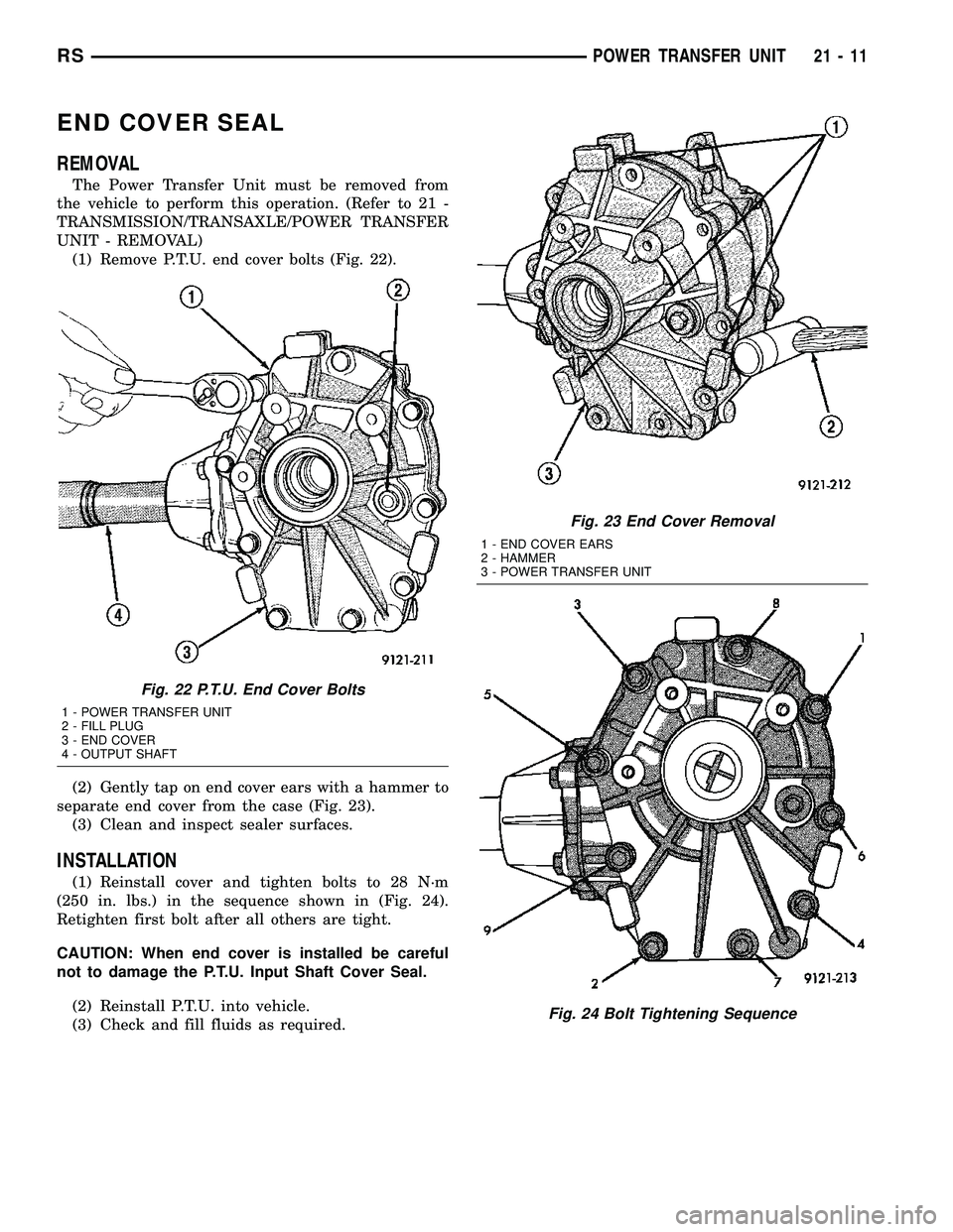
(1) Remove P.T.U. end cover bolts (Fig. 22).
(2) Gently tap on end cover ears with a hammer to
separate end cover from the case (Fig. 23).
(3) Clean and inspect sealer surfaces.
INSTALLATION
(1) Reinstall cover and tighten bolts to 28 N´m
(250 in. lbs.) in the sequence shown in (Fig. 24).
Retighten first bolt after all others are tight.
CAUTION: When end cover is installed be careful
not to damage the P.T.U. Input Shaft Cover Seal.
(2) Reinstall P.T.U. into vehicle.
(3) Check and fill fluids as required.
Fig. 22 P.T.U. End Cover Bolts
1 - POWER TRANSFER UNIT
2 - FILL PLUG
3 - END COVER
4 - OUTPUT SHAFT
Fig. 23 End Cover Removal
1 - END COVER EARS
2 - HAMMER
3 - POWER TRANSFER UNIT
Fig. 24 Bolt Tightening Sequence
RSPOWER TRANSFER UNIT21-11
Page 1631 of 2585
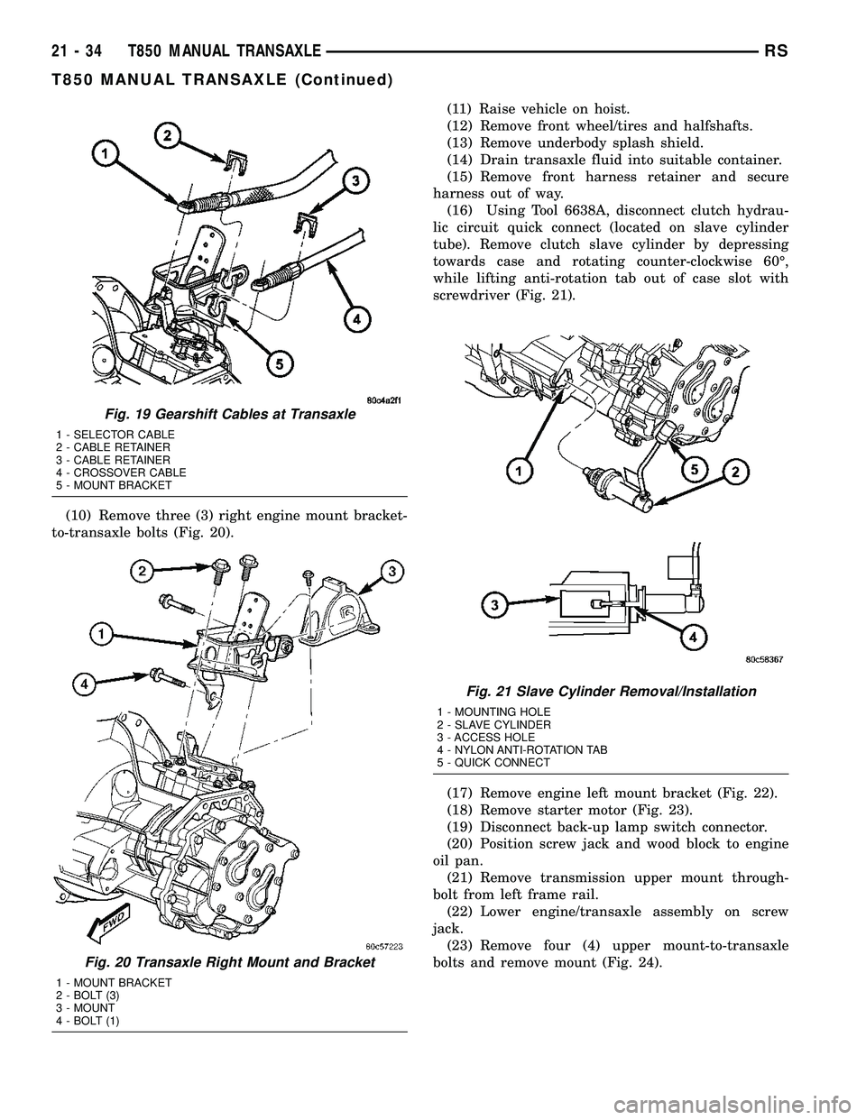
(10) Remove three (3) right engine mount bracket-
to-transaxle bolts (Fig. 20).(11) Raise vehicle on hoist.
(12) Remove front wheel/tires and halfshafts.
(13) Remove underbody splash shield.
(14) Drain transaxle fluid into suitable container.
(15) Remove front harness retainer and secure
harness out of way.
(16) Using Tool 6638A, disconnect clutch hydrau-
lic circuit quick connect (located on slave cylinder
tube). Remove clutch slave cylinder by depressing
towards case and rotating counter-clockwise 60É,
while lifting anti-rotation tab out of case slot with
screwdriver (Fig. 21).
(17) Remove engine left mount bracket (Fig. 22).
(18) Remove starter motor (Fig. 23).
(19) Disconnect back-up lamp switch connector.
(20) Position screw jack and wood block to engine
oil pan.
(21) Remove transmission upper mount through-
bolt from left frame rail.
(22) Lower engine/transaxle assembly on screw
jack.
(23) Remove four (4) upper mount-to-transaxle
bolts and remove mount (Fig. 24).
Fig. 19 Gearshift Cables at Transaxle
1 - SELECTOR CABLE
2 - CABLE RETAINER
3 - CABLE RETAINER
4 - CROSSOVER CABLE
5 - MOUNT BRACKET
Fig. 20 Transaxle Right Mount and Bracket
1 - MOUNT BRACKET
2 - BOLT (3)
3 - MOUNT
4 - BOLT (1)
Fig. 21 Slave Cylinder Removal/Installation
1 - MOUNTING HOLE
2 - SLAVE CYLINDER
3 - ACCESS HOLE
4 - NYLON ANTI-ROTATION TAB
5 - QUICK CONNECT
21 - 34 T850 MANUAL TRANSAXLERS
T850 MANUAL TRANSAXLE (Continued)
Page 1653 of 2585
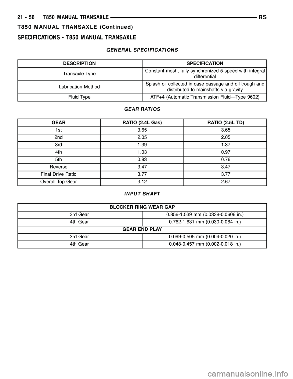
SPECIFICATIONS - T850 MANUAL TRANSAXLE
GENERAL SPECIFICATIONS
DESCRIPTION SPECIFICATION
Transaxle TypeConstant-mesh, fully synchronized 5-speed with integral
differential
Lubrication MethodSplash oil collected in case passage and oil trough and
distributed to mainshafts via gravity
Fluid Type ATF+4 (Automatic Transmission FluidÐType 9602)
GEAR RATIOS
GEAR RATIO (2.4L Gas) RATIO (2.5L TD)
1st 3.65 3.65
2nd 2.05 2.05
3rd 1.39 1.37
4th 1.03 0.97
5th 0.83 0.76
Reverse 3.47 3.47
Final Drive Ratio 3.77 3.77
Overall Top Gear 3.12 2.67
INPUT SHAFT
BLOCKER RING WEAR GAP
3rd Gear 0.856-1.539 mm (0.0338-0.0606 in.)
4th Gear 0.762-1.631 mm (0.030-0.064 in.)
GEAR END PLAY
3rd Gear 0.099-0.505 mm (0.004-0.020 in.)
4th Gear 0.048-0.457 mm (0.002-0.018 in.)
21 - 56 T850 MANUAL TRANSAXLERS
T850 MANUAL TRANSAXLE (Continued)
Page 1658 of 2585
AXLE SEALS
REMOVAL
(1) Raise vehicle on hoist.
(2) Remove one or both front halfshaft assemblies.
(Refer to 3 - DIFFERENTIAL & DRIVELINE/HALF
SHAFT - REMOVAL)
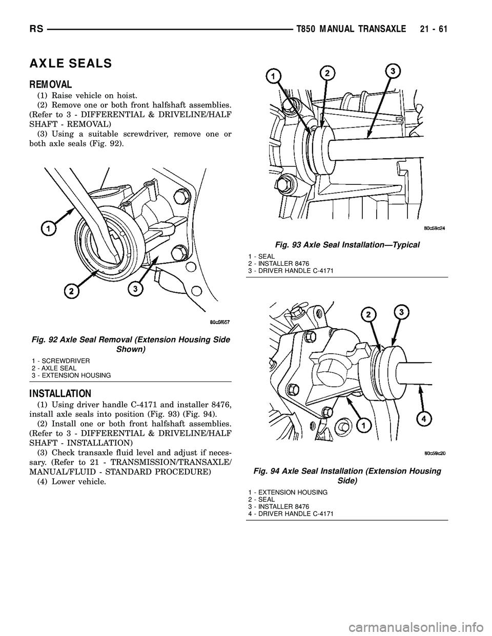
(3) Using a suitable screwdriver, remove one or
both axle seals (Fig. 92).
INSTALLATION
(1) Using driver handle C-4171 and installer 8476,
install axle seals into position (Fig. 93) (Fig. 94).
(2) Install one or both front halfshaft assemblies.
(Refer to 3 - DIFFERENTIAL & DRIVELINE/HALF
SHAFT - INSTALLATION)
(3) Check transaxle fluid level and adjust if neces-
sary. (Refer to 21 - TRANSMISSION/TRANSAXLE/
MANUAL/FLUID - STANDARD PROCEDURE)
(4) Lower vehicle.
Fig. 92 Axle Seal Removal (Extension Housing Side
Shown)
1 - SCREWDRIVER
2 - AXLE SEAL
3 - EXTENSION HOUSING
Fig. 93 Axle Seal InstallationÐTypical
1 - SEAL
2 - INSTALLER 8476
3 - DRIVER HANDLE C-4171
Fig. 94 Axle Seal Installation (Extension Housing
Side)
1 - EXTENSION HOUSING
2 - SEAL
3 - INSTALLER 8476
4 - DRIVER HANDLE C-4171
RST850 MANUAL TRANSAXLE21-61
Page 1668 of 2585
If end play measurement indicates a thrust washer
change is necessary, the differential must be disas-
sembled. (Refer to 21 - TRANSMISSION/TRANS-
AXLE/MANUAL/DIFFERENTIAL - DISASSEMBLY)FLUID
STANDARD PROCEDURE
STANDARD PROCEDURE - FLUID LEVEL
CHECK
NOTE: For proper fluid level check intervals, (Refer
to LUBRICATION & MAINTENANCE/MAINTENANCE
SCHEDULES - DESCRIPTION)
The fluid required in this transaxle is Mopart
ATF+4. Use of substitute fluids may result in
improper transaxle operation and/or failure.
(1) Raise vehicle on hoist.
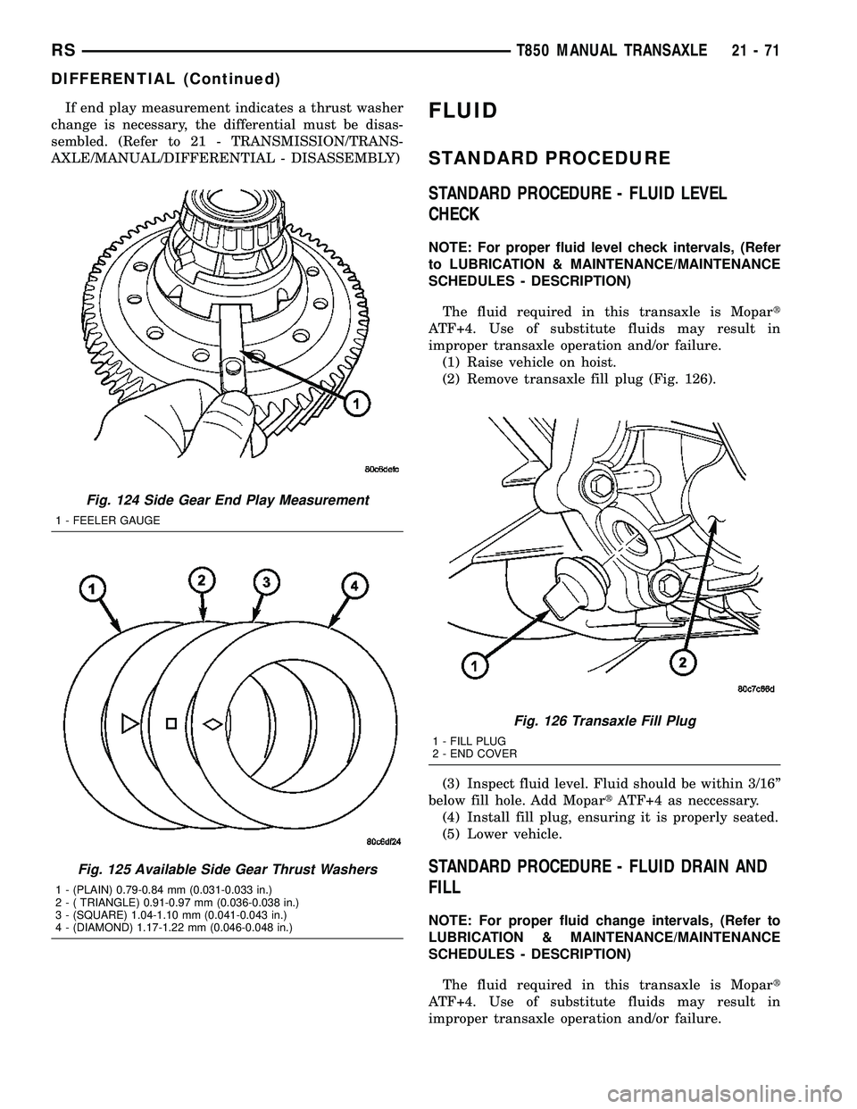
(2) Remove transaxle fill plug (Fig. 126).
(3) Inspect fluid level. Fluid should be within 3/16º
below fill hole. Add MopartATF+4 as neccessary.
(4) Install fill plug, ensuring it is properly seated.
(5) Lower vehicle.
STANDARD PROCEDURE - FLUID DRAIN AND
FILL
NOTE: For proper fluid change intervals, (Refer to
LUBRICATION & MAINTENANCE/MAINTENANCE
SCHEDULES - DESCRIPTION)
The fluid required in this transaxle is Mopart
ATF+4. Use of substitute fluids may result in
improper transaxle operation and/or failure.
Fig. 124 Side Gear End Play Measurement
1 - FEELER GAUGE
Fig. 125 Available Side Gear Thrust Washers
1 - (PLAIN) 0.79-0.84 mm (0.031-0.033 in.)
2 - ( TRIANGLE) 0.91-0.97 mm (0.036-0.038 in.)
3 - (SQUARE) 1.04-1.10 mm (0.041-0.043 in.)
4 - (DIAMOND) 1.17-1.22 mm (0.046-0.048 in.)
Fig. 126 Transaxle Fill Plug
1 - FILL PLUG
2 - END COVER
RST850 MANUAL TRANSAXLE21-71
DIFFERENTIAL (Continued)