Page 299 of 410
What to Add
When you do need brake fluid, use only DOT-3 brake
fluid. Use new brake fluid from a sealed container
only. SeeRecommended Fluids and Lubricants on
page 6-12.
Always clean the brake fluid reservoir cap and the area
around the cap before removing it. This will help
keep dirt from entering the reservoir.
{CAUTION:
With the wrong kind of fluid in your brake
system, your brakes may not work well, or
they may not even work at all. This could
cause a crash. Always use the proper brake
fluid.Notice:
•Using the wrong fluid can badly damage brake
system parts. For example, just a few drops of
mineral-based oil, such as engine oil, in your
brake system can damage brake system
parts so badly that they will have to be replaced.
Do not let someone put in the wrong kind of
fluid.
•If you spill brake fluid on your vehicle’s painted
surfaces, the paint finish can be damaged. Be
careful not to spill brake fluid on your vehicle. If
you do, wash it off immediately. SeeAppearance
Care on page 5-87.
5-39
Page 304 of 410
4. Open the hoods and locate the positive (+) and
negative (−) terminal locations on the other
vehicle. Your vehicle has a remote (+) jump starting
terminal and a remote negative (−) jump starting
terminal. You should always use these remote
terminals instead of the terminals on the battery.
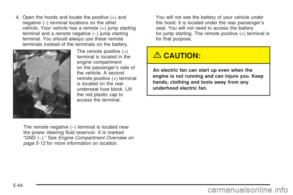
The remote positive (+)
terminal is located in the
engine compartment
on the passenger’s side of
the vehicle. A second
remote positive (+) terminal
is located on the rear
underseat fuse block. Lift
the red plastic cap to
access the terminal.
The remote negative (−) terminal is located near
the power steering fluid reservoir. It is marked
“GND (−).” SeeEngine Compartment Overview on
page 5-12for more information on location.You will not see the battery of your vehicle under
the hood. It is located under the rear passenger’s
seat. You will not need to access the battery
for jump starting. The remote positive (+) terminal is
for that purpose.
{CAUTION:
An electric fan can start up even when the
engine is not running and can injure you. Keep
hands, clothing and tools away from any
underhood electric fan.
5-44
Page 305 of 410
{CAUTION:
Using a match near a battery can cause battery
gas to explode. People have been hurt doing
this, and some have been blinded. Use a
flashlight if you need more light.
Be sure the battery has enough water. You do
not need to add water to the ACDelco
®battery
installed in your new vehicle. But if a battery
has filler caps, be sure the right amount of
fluid is there. If it is low, add water to take care
of that first. If you do not, explosive gas could
be present.
Battery fluid contains acid that can burn you.
Do not get it on you. If you accidentally get it
in your eyes or on your skin, flush the place
with water and get medical help immediately.
{CAUTION:
Fans or other moving engine parts can injure
you badly. Keep your hands away from moving
parts once the engine is running.
5. Check that the jumper cables do not have loose or
missing insulation. If they do, you could get a
shock. The vehicles could also be damaged, too.
Before you connect the cables, here are some basic
things you should know. Positive (+) will go to
positive (+) or to a remote positive (+) terminal if the
vehicle has one. Negative (−) will go to a heavy,
unpainted metal engine part or to a remote
negative (−) terminal if the vehicle has one.
Do not connect positive (+) to the negative (−)or
you will get a short that would damage the battery
and maybe other parts, too. And do not connect
the negative (−) cable to negative (−) terminal on the
dead battery because this can cause sparks.
5-45
Page 306 of 410
6. Connect the red
positive (+) cable to the
remote positive (+)
terminal location on the
vehicle with the dead
battery. Use a
remote positive (+)
terminal if the vehicle
has one.
7. Do not let the other
end touch metal.
Connect it to the
positive (+) terminal
location of the vehicle
with the good
battery. Use a remote
positive (+) terminal
if the vehicle has one.8. Now connect the black
negative (−) cable to
the negative (−)
terminal location of the
vehicle with the
good battery. Use
a remote
negative (−) terminal
if the vehicle
has one.
Do not let the other end of the cable touch anything
until the next step. The other end of the negative (−)
cable does not go to the dead battery. It goes to a
heavy, unpainted metal engine part or to a remote
negative (−) terminal on the vehicle with the dead
battery.
5-46
Page 307 of 410
9. Connect the other end
of the negative (−) cable
to the negative (−)
terminal location on the
vehicle with the dead
battery. Your vehicle
has a remote
negative (−) terminal
marked GND (−).
10. Now start the vehicle with the good battery and run
the engine for a while.11. Try to start the vehicle with the dead battery. If it
will not start after a few tries, it probably needs
service.
Notice:If the jumper cables are removed in the
wrong order, electrical shorting may occur and
damage the vehicle. The repairs would not be
covered by your warranty. Remove the jumper
cables in the correct order, making sure that the
cables do not touch each other or other metal.
5-47
Page 308 of 410
A. Dead Battery or Remote Positive (+) Terminal
B. Good Battery or Remote Positive (+) and Remote
Negative (−) Terminals
C. Heavy, Unpainted Metal Engine Part or Remote
Negative (−) Terminal (GND)To disconnect the jumper cables from both vehicles, do
the following:
1. Disconnect the black negative (−) cable from the
vehicle that had the dead battery.
2. Disconnect the black negative (−) cable from the
vehicle with the good battery.
3. Disconnect the red positive (+) cable from the
vehicle with the good battery.
4. Disconnect the red positive (+) cable from the other
vehicle.
5. Return the remote positive (+) terminal cover to its
original position.
Jumper Cable Removal
5-48
Page 325 of 410
Tire Size
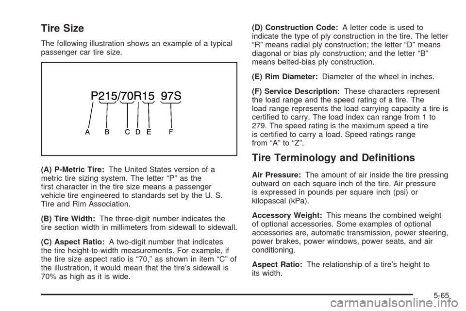
The following illustration shows an example of a typical
passenger car tire size.
(A) P-Metric Tire:The United States version of a
metric tire sizing system. The letter “P” as the
first character in the tire size means a passenger
vehicle tire engineered to standards set by the U. S.
Tire and Rim Association.
(B) Tire Width:The three-digit number indicates the
tire section width in millimeters from sidewall to sidewall.
(C) Aspect Ratio:A two-digit number that indicates
the tire height-to-width measurements. For example, if
the tire size aspect ratio is “70,” as shown in item “C” of
the illustration, it would mean that the tire’s sidewall is
70% as high as it is wide.(D) Construction Code:A letter code is used to
indicate the type of ply construction in the tire. The letter
“R” means radial ply construction; the letter “D” means
diagonal or bias ply construction; and the letter “B”
means belted-bias ply construction.
(E) Rim Diameter:Diameter of the wheel in inches.
(F) Service Description:These characters represent
the load range and the speed rating of a tire. The
load range represents the load carrying capacity a tire is
certified to carry. The load index can range from 1 to
279. The speed rating is the maximum speed a tire
is certified to carry a load. Speed ratings range
from “A” to “Z”.
Tire Terminology and Definitions
Air Pressure:The amount of air inside the tire pressing
outward on each square inch of the tire. Air pressure
is expressed in pounds per square inch (psi) or
kilopascal (kPa).
Accessory Weight:This means the combined weight
of optional accessories. Some examples of optional
accessories are, automatic transmission, power steering,
power brakes, power windows, power seats, and air
conditioning.
Aspect Ratio:The relationship of a tire’s height to
its width.
5-65
Page 330 of 410
This device complies with Part 15 of the FCC Rules.
Operation is subject to the following two conditions:
(1) this device may not cause harmful interference, and
(2) this device must accept any interference received,
including interference that may cause undesired
operation.
This device complies with RSS-210 of Industry and
Science Canada. Operation is subject to the following
two conditions: (1) this device may not cause
interference, and (2) this device must accept any
interference received, including interference that may
cause undesired operation of the device.
Changes or modifications to this system by anyone
other than an authorized service facility could void
authorization to use this equipment.
If the TPM system detects low tire pressure, below
25 psi (172 kPa), or high tire pressure, above 38 psi
(262 kPa), a message, CHECK TIRE PRESSURE, will
appear on the Driver Information Center (DIC)
display. By pressing the INFO button, the DIC screen
will show which tire(s) has the low or high pressure
condition. SeeIn�ation - Tire Pressure on page 5-68for
information regarding correct tire inflation. If a tire is
low, you should stop as soon as possible and check all
your tires for damage. If a tire is flat, seeIf a Tire
Goes Flat on page 5-77.Notice:Do not use a tire sealant if your vehicle is
equipped with Tire Pressure Monitors. The liquid
sealant can damage the tire pressure monitor
sensors.
Once a low or high tire pressure condition is detected,
the TPM system will display the CHECK TIRE
MESSAGE each time the engine is started, until the
tire(s) are set to the correct inflation pressure.
The Tire-Loading Information Label, which is located on
the rear edge of the driver’s door, shows the correct
inflation pressure for the tires on your vehicle.
The TPM system also allows the driver to check the air
pressure status of each road tire using the Driver
Information Center (DIC). Each tire’s air pressure will be
listed individually, in the following order: LF (left front
or driver’s side front tire), RF (right front or passenger’s
side front tire), RR (right rear or passenger’s side
rear tire) and LR (left rear or driver’s side rear tire). See
In�ation - Tire Pressure on page 5-68for information
regarding correct tire inflation. Also, seeDriver
Information Center (DIC) on page 3-52for information
on the DIC controls and displays.
If the DIC display does not show tire pressures or the
SERVICE TPM SYSTEM message appears, see
your dealer for service. The TPM system may not work
properly while the compact spare tire is installed.
5-70