Page 380 of 578
4 - 68
ENGCRANKCASE, CRANKSHAFT AND BALANCER
Extent of removal Order Part name Q’ty Remarks
1 Intake timing chain guide 1
2 Timing chain 1
3 Bolt [45 mm (1.8 in)] 7
4 Bolt [55 mm (2.2 in)] 1
5 Bolt [30 mm (1.2 in)] 2
6 Lead guide 1
7 Clutch cable holder 1
8 Right crankcase 1
Use special tool.
Refer to “REMOVAL POINTS”.
9 Left crankcase 1
10 Balancer 1
11 Crankshaft 1 Use special tool.
Refer to “REMOVAL POINTS”.
12 Bearing 3 Refer to “REMOVAL POINTS”.
3
21
Page 382 of 578

�Lead guide 1
�Clutch cable holder 2
NOTE:
Loosen each bolt 1/4 of a turn at a time and
after all t")
4 - 69
ENGCRANKCASE, CRANKSHAFT AND BALANCER
REMOVAL POINTS
Crankcase
1. Remove:
�Bolt (crankcase)
�Lead guide 1
�Clutch cable holder 2
NOTE:
Loosen each bolt 1/4 of a turn at a time and
after all the bolts are loosened, remove them.
2. Remove:
�Right crankcase 1
Use the crankcase separating tool 2.
NOTE:
�Fully tighten the tool holding bolts, but make
sure the tool body is parallel with the case. If
necessary, one screw may be backed out
slightly to level tool body.
�As pressure is applied, alternately tap on the
front engine mounting boss and transmission
shafts.
CAUTION:
Use soft hammer to tap on the case half.
Tap only on reinforced portions of case. Do
not tap on gasket mating surface. Work
slowly and carefully. Make sure the case
halves separate evenly. If one end “hangs
up”, take pressure off the push screw, re-
align, and start over. If the cases do not
separate, check for a remaining case screw
or fitting. Do not force.
Crankcase separating tool:
YU-1135-A/90890-01135
Page 384 of 578
4 - 70
ENGCRANKCASE, CRANKSHAFT AND BALANCER
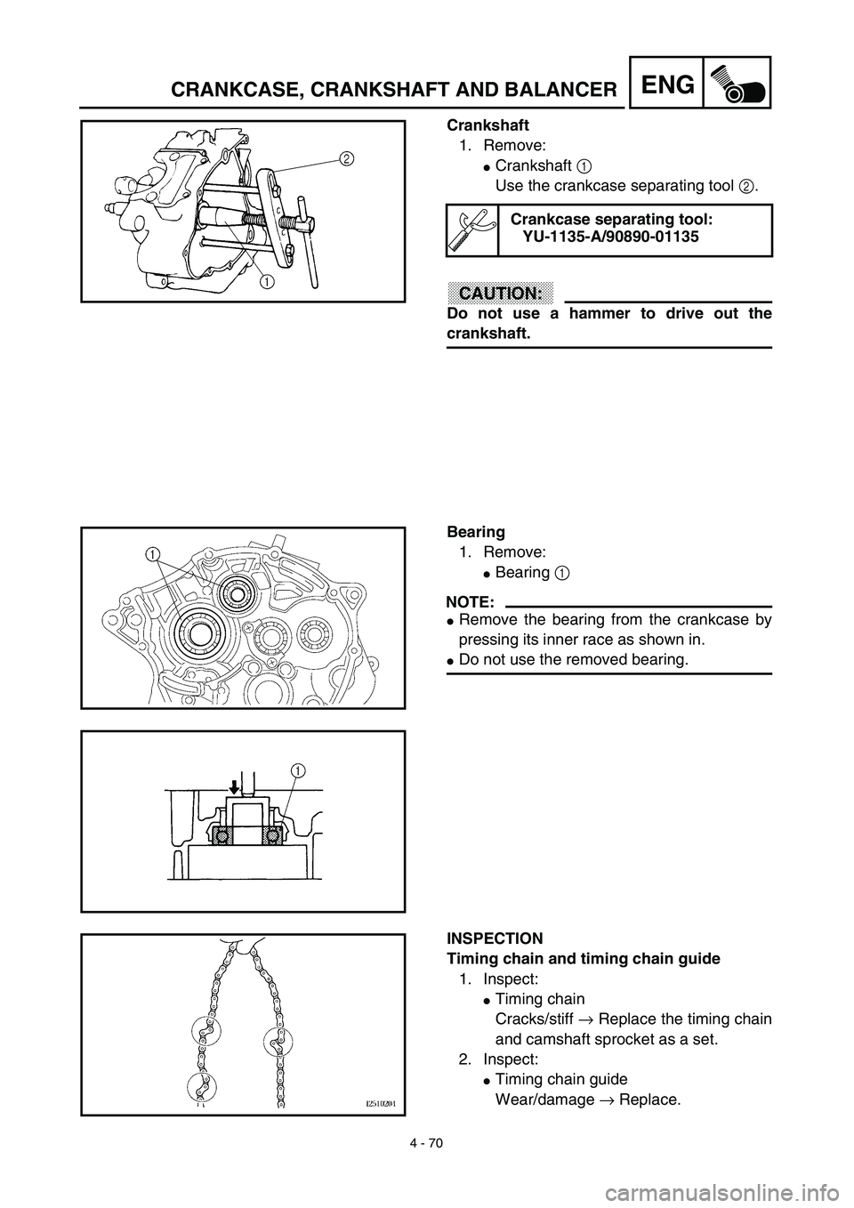
Crankshaft
1. Remove:
�Crankshaft 1
Use the crankcase separating tool 2.
CAUTION:
Do not use a hammer to drive out the
crankshaft.
Crankcase separating tool:
YU-1135-A/90890-01135
Bearing
1. Remove:
�Bearing 1
NOTE:
�Remove the bearing from the crankcase by
pressing its inner race as shown in.
�Do not use the removed bearing.
INSPECTION
Timing chain and timing chain guide
1. Inspect:
�Timing chain
Cracks/stiff → Replace the timing chain
and camshaft sprocket as a set.
2. Inspect:
�Timing chain guide
Wear/damage → Replace.
Page 386 of 578
4 - 71
ENGCRANKCASE, CRANKSHAFT AND BALANCER
Crankcase
1. Inspect:
�Contacting surface a
Scratches → Replace.
�Engine mounting boss b, crankcase
Cracks/damage → Replace.
2. Inspect:
�Bearing
Rotate inner race with a finger.
Rough spot/seizure → Replace.
Crankshaft
1. Measure:
�Runout limit a
�Connecting rod big end side clearance
b
�Crank width c
Out of specification → Replace.
Use the dial gauge and a thickness
gauge.
Dial gauge & stand set:
YU-3097/90890-01252
Standard
Runout
limit:—0.03 mm
(0.0012 in)
Side
clearance:0.15 ~ 0.45 mm
(0.0059 ~ 0.0177 in)0.50 mm
(0.02 in)
Crack
width:46.95 ~ 47.00 mm
(1.848 ~ 1.850 in)—
Page 388 of 578
4 - 72
ENGCRANKCASE, CRANKSHAFT AND BALANCER
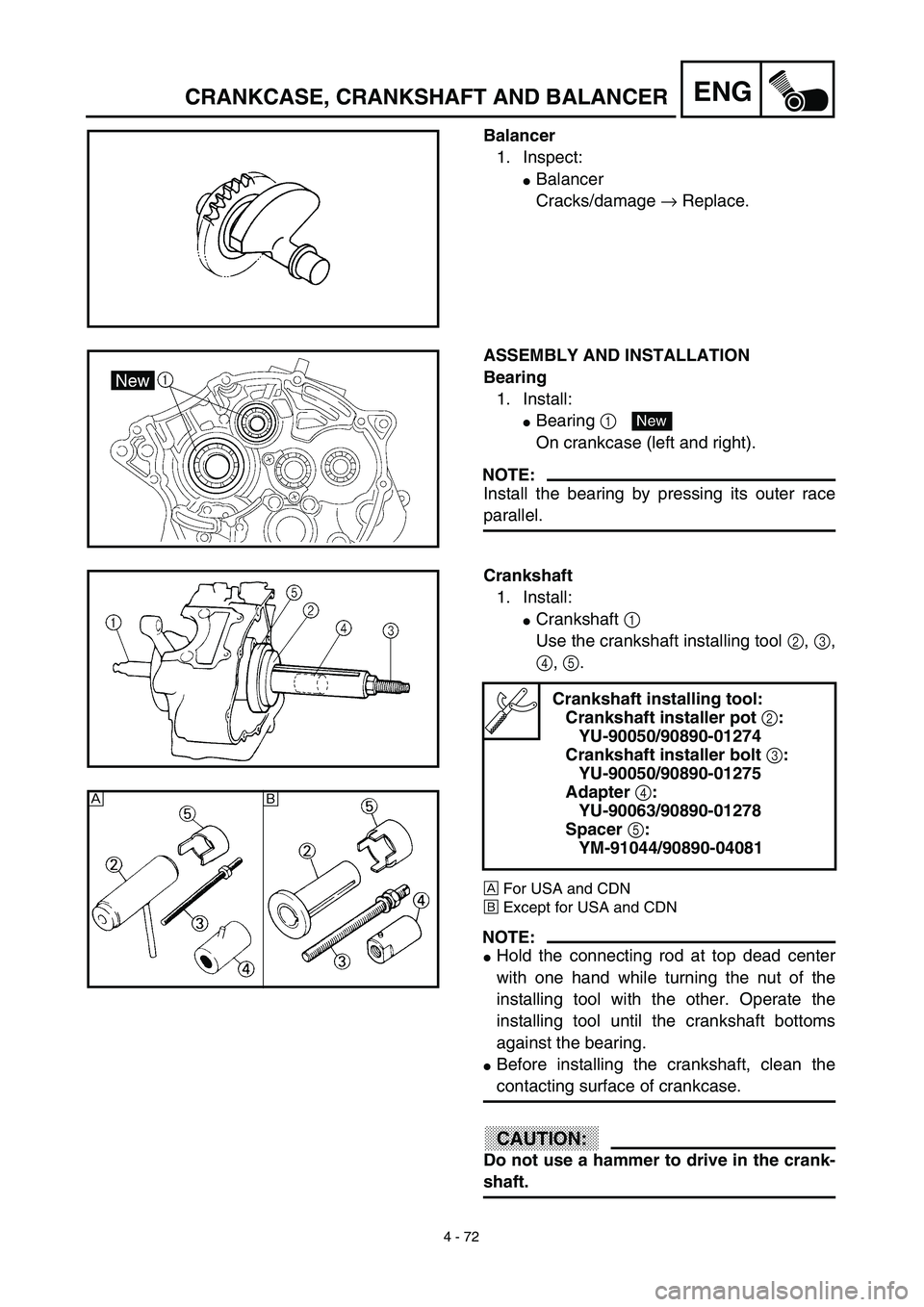
Balancer
1. Inspect:
�Balancer
Cracks/damage → Replace.
ASSEMBLY AND INSTALLATION
Bearing
1. Install:
�Bearing 1
On crankcase (left and right).
NOTE:
Install the bearing by pressing its outer race
parallel.
New
Crankshaft
1. Install:
�Crankshaft 1
Use the crankshaft installing tool 2, 3,
4, 5.
ÅFor USA and CDN
ıExcept for USA and CDN
NOTE:
�Hold the connecting rod at top dead center
with one hand while turning the nut of the
installing tool with the other. Operate the
installing tool until the crankshaft bottoms
against the bearing.
�Before installing the crankshaft, clean the
contacting surface of crankcase.
CAUTION:
Do not use a hammer to drive in the crank-
shaft.
Crankshaft installing tool:
Crankshaft installer pot 2:
YU-90050/90890-01274
Crankshaft installer bolt 3:
YU-90050/90890-01275
Adapter 4:
YU-90063/90890-01278
Spacer 5:
YM-91044/90890-04081
Å
ı
Page 390 of 578
4 - 73
ENGCRANKCASE, CRANKSHAFT AND BALANCER
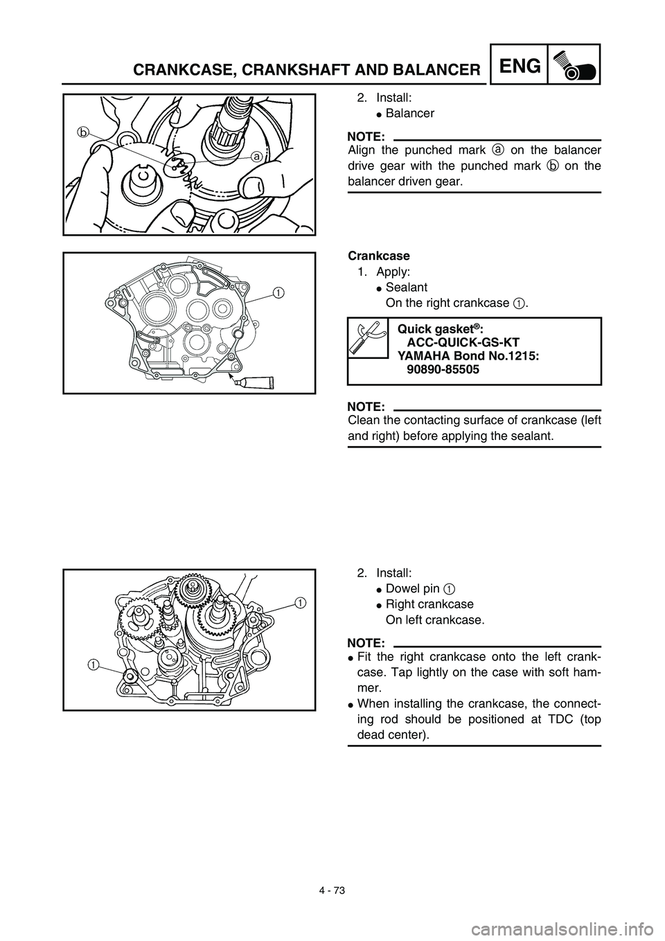
2. Install:
�Balancer
NOTE:
Align the punched mark a on the balancer
drive gear with the punched mark b on the
balancer driven gear.
Crankcase
1. Apply:
�Sealant
On the right crankcase 1.
NOTE:
Clean the contacting surface of crankcase (left
and right) before applying the sealant.
Quick gasket®:
ACC-QUICK-GS-KT
YAMAHA Bond No.1215:
90890-85505
2. Install:
�Dowel pin 1
�Right crankcase
On left crankcase.
NOTE:
�Fit the right crankcase onto the left crank-
case. Tap lightly on the case with soft ham-
mer.
�When installing the crankcase, the connect-
ing rod should be positioned at TDC (top
dead center).
Page 392 of 578
4 - 74
ENGCRANKCASE, CRANKSHAFT AND BALANCER
3. Tighten:
�Lead guide 1
�Clutch cable holder 2
�Bolt (crankcase) [45 mm (1.8 in)] 3
�Bolt (crankcase) [55 mm (2.2 in)] 4
�Bolt (crankcase) [30 mm (1.2 in)] 5
NOTE:
�Apply Quick gasket® (YAMAHA Bond
No.1215) on end of the crankcase bolts [45
mm (1.8 in)] 3, as shown.
�Tighten the crankcase bolts in stage, using a
crisscross pattern.
Quick gasket®:
ACC-QUICK-GS-KT
YAMAHA Bond No.1215:
90890-85505
T R..10 Nm (1.0 m · kg, 7.2 ft · lb)
T R..10 Nm (1.0 m · kg, 7.2 ft · lb)
T R..10 Nm (1.0 m · kg, 7.2 ft · lb)
4. Check:
�Crankshaft and transmission operation
Unsmooth operation → Repair.
5. Install:
�Timing chain 1
�Intake timing chain guide 2
�Bolt (intake timing chain guide)
T R..10 Nm (1.0 m · kg, 7.2 ft · lb)LT
Page 394 of 578
4 - 75
ENGTRANSMISSION, SHIFT CAM AND SHIFT FORK
TRANSMISSION, SHIFT CAM AND SHIFT FORK
Extent of removal:1 Shift cam and shift fork removal2 Main axle and drive axle removal
Extent of removal Order Part name Q’ty Remarks
TRANSMISSION, SHIFTCAM
AND SHIFT FORK REMOVAL
Preparation for removal Engine Refer to “ENGINE REMOVAL” section.
Separate the crankcase. Refer to “CRANKCASE, CRANKSHAFT
AND BALANCER” section.
1 Shift fork guide bar 1 (short) 1
2 Shift fork guide bar 2 (long) 1
3 Shift cam 1
4 Shift fork 2 (C) 1
5 Shift fork 3 (R) 1
6 Shift fork 1 (L) 1
7 Main axle 1
Refer to “REMOVAL POINTS”.
8 Drive axle 1
9 Push rod 2 1
10 Washer 1
1
2
![YAMAHA TTR125 2003 Owners Manual 4 - 68
ENGCRANKCASE, CRANKSHAFT AND BALANCER
Extent of removal Order Part name Q’ty Remarks
1 Intake timing chain guide 1
2 Timing chain 1
3 Bolt [45 mm (1.8 in)] 7
4 Bolt [55 mm (2.2 in)] 1
5 Bolt](/manual-img/51/51647/w960_51647-379.png "YAMAHA TTR125 2003 Owners Manual 4 - 68
ENGCRANKCASE, CRANKSHAFT AND BALANCER
Extent of removal Order Part name Q’ty Remarks
1 Intake timing chain guide 1
2 Timing chain 1
3 Bolt [45 mm (1.8 in)] 7
4 Bolt [55 mm (2.2 in)] 1
5 Bolt")