Page 272 of 578
4 - 14
ENGCYLINDER HEAD
REMOVAL POINTS
Cylinder head
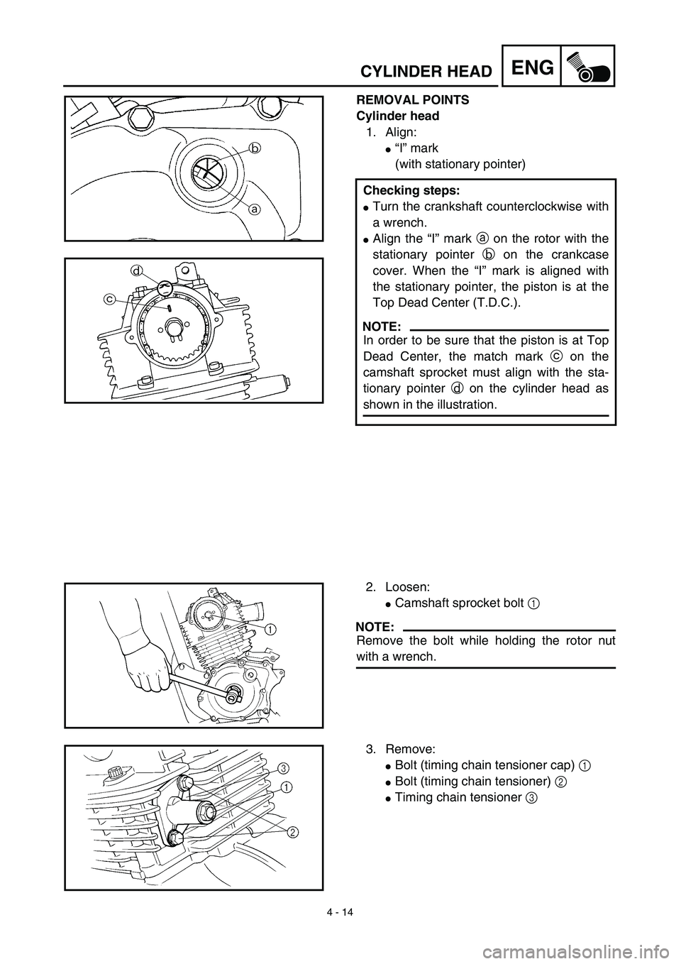
1. Align:
�“I” mark
(with stationary pointer)
Checking steps:
�Turn the crankshaft counterclockwise with
a wrench.
�Align the “I” mark a on the rotor with the
stationary pointer b on the crankcase
cover. When the “I” mark is aligned with
the stationary pointer, the piston is at the
Top Dead Center (T.D.C.).
NOTE:
In order to be sure that the piston is at Top
Dead Center, the match mark c on the
camshaft sprocket must align with the sta-
tionary pointer d on the cylinder head as
shown in the illustration.
2. Loosen:
�Camshaft sprocket bolt 1
NOTE:
Remove the bolt while holding the rotor nut
with a wrench.
3. Remove:
�Bolt (timing chain tensioner cap) 1
�Bolt (timing chain tensioner) 2
�Timing chain tensioner 3
Page 274 of 578
4 - 15
ENGCYLINDER HEAD
4. Remove:
�Bolt (camshaft sprocket) 1
�Camshaft sprocket 2
NOTE:
Attach a wire a to the timing chain to prevent
it from falling into the crankcase.
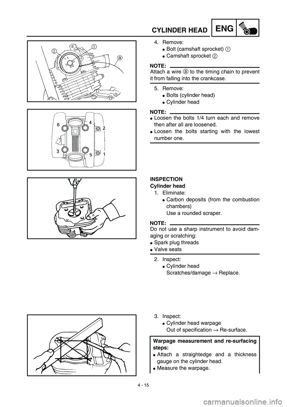
5. Remove:
�Bolts (cylinder head)
�Cylinder head
NOTE:
�Loosen the bolts 1/4 turn each and remove
then after all are loosened.
�Loosen the bolts starting with the lowest
number one.
INSPECTION
Cylinder head
1. Eliminate:
�Carbon deposits (from the combustion
chambers)
Use a rounded scraper.
NOTE:
Do not use a sharp instrument to avoid dam-
aging or scratching:
�Spark plug threads
�Valve seats
2. Inspect:
�Cylinder head
Scratches/damage → Replace.
3. Inspect:
�Cylinder head warpage
Out of specification → Re-surface.
Warpage measurement and re-surfacing
steps:
�Attach a straightedge and a thickness
gauge on the cylinder head.
�Measure the warpage.
Page 278 of 578
4 - 17
ENGCYLINDER HEAD
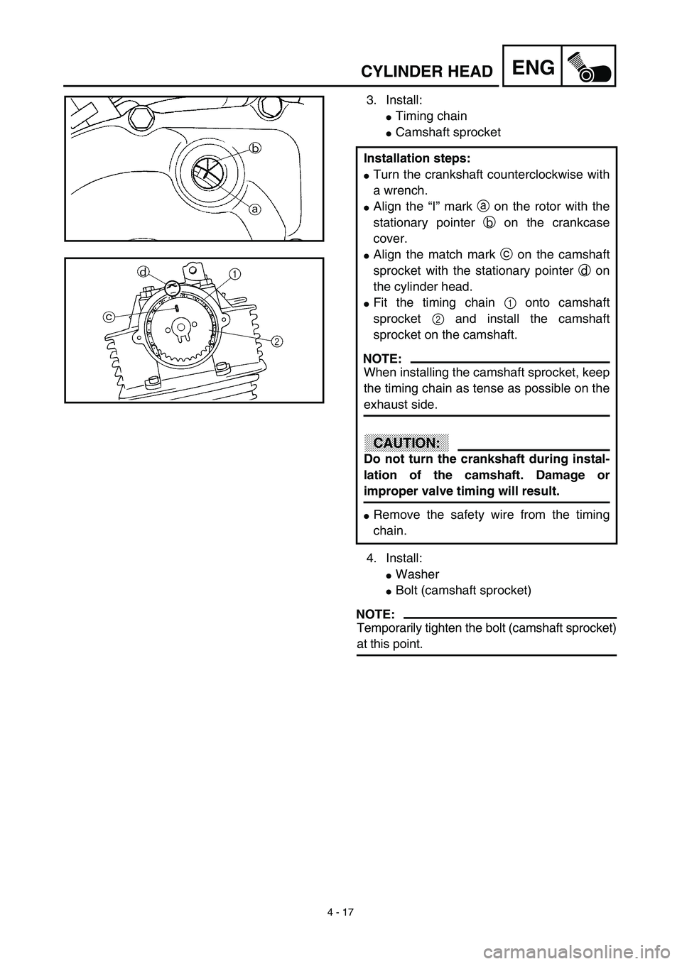
3. Install:
�Timing chain
�Camshaft sprocket
4. Install:
�Washer
�Bolt (camshaft sprocket)
NOTE:
Temporarily tighten the bolt (camshaft sprocket)
at this point. Installation steps:
�Turn the crankshaft counterclockwise with
a wrench.
�Align the “I” mark a on the rotor with the
stationary pointer b on the crankcase
cover.
�Align the match mark c on the camshaft
sprocket with the stationary pointer d on
the cylinder head.
�Fit the timing chain 1 onto camshaft
sprocket 2 and install the camshaft
sprocket on the camshaft.
NOTE:
When installing the camshaft sprocket, keep
the timing chain as tense as possible on the
exhaust side.
CAUTION:
Do not turn the crankshaft during instal-
lation of the camshaft. Damage or
improper valve timing will result.
�Remove the safety wire from the timing
chain.
Page 280 of 578
4 - 18
ENGCYLINDER HEAD
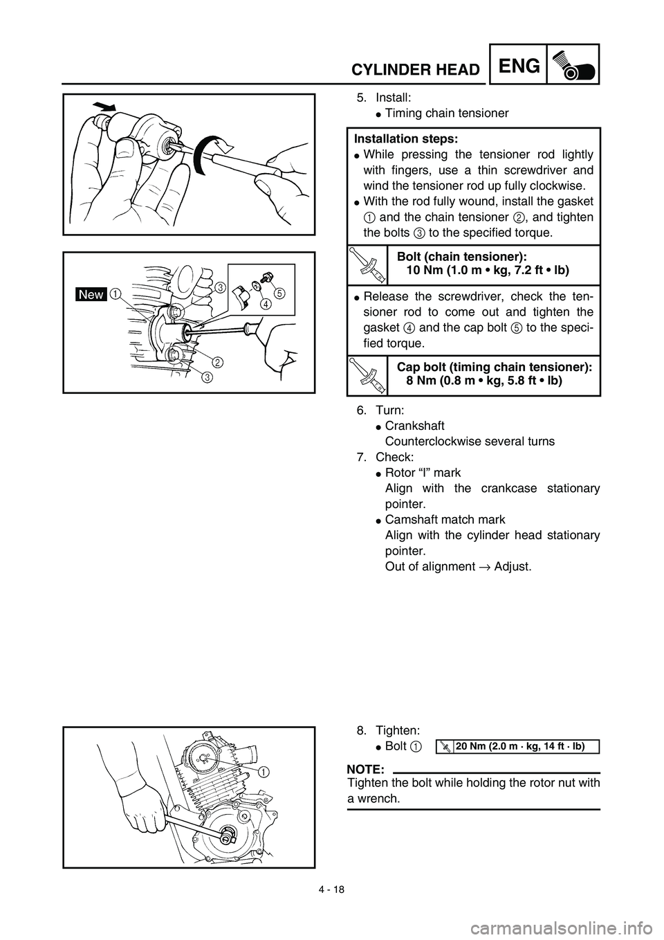
5. Install:
�Timing chain tensioner
6. Turn:
�Crankshaft
Counterclockwise several turns
7. Check:
�Rotor “I” mark
Align with the crankcase stationary
pointer.
�Camshaft match mark
Align with the cylinder head stationary
pointer.
Out of alignment → Adjust. Installation steps:
�While pressing the tensioner rod lightly
with fingers, use a thin screwdriver and
wind the tensioner rod up fully clockwise.
�With the rod fully wound, install the gasket
1 and the chain tensioner 2, and tighten
the bolts 3 to the specified torque.
T R..
Bolt (chain tensioner):
10 Nm (1.0 m • kg, 7.2 ft • lb)
�Release the screwdriver, check the ten-
sioner rod to come out and tighten the
gasket 4 and the cap bolt 5 to the speci-
fied torque.
T R..
Cap bolt (timing chain tensioner):
8 Nm (0.8 m • kg, 5.8 ft • lb)
8. Tighten:
�Bolt 1
NOTE:
Tighten the bolt while holding the rotor nut with
a wrench.
T R..20 Nm (2.0 m · kg, 14 ft · lb)
Page 310 of 578
4 - 33
ENG
CYLINDER AND PISTON
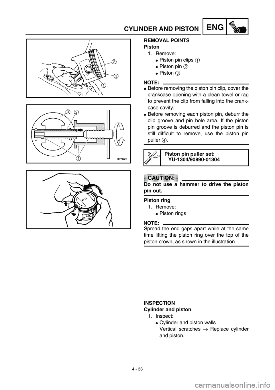
REMOVAL POINTS
Piston
1. Remove:
�
Piston pin clips
1
�
Piston pin
2
�
Piston
3
NOTE:
�
Before removing the piston pin clip, cover the
crankcase opening with a clean towel or rag
to prevent the clip from falling into the crank-
case cavity.
�
Before removing each piston pin, deburr the
clip groove and pin hole area. If the piston
pin groove is deburred and the piston pin is
still difficult to remove, use the piston pin
puller
4
.
CAUTION:
Do not use a hammer to drive the piston
pin out.
Piston ring
1. Remove:
�
Piston rings
NOTE:
Spread the end gaps apart while at the same
time lifting the piston ring over the top of the
piston crown, as shown in the illustration.
Piston pin puller set:
YU-1304/90890-01304
INSPECTION
Cylinder and piston
1. Inspect:
�
Cylinder and piston walls
Vertical scratches
→
Replace cylinder
and piston.
Page 320 of 578

NOTE:
�Be sure to install the 2nd piston ring so that
the manufacturer’s ma")
4 - 38
ENGCYLINDER AND PISTON
ASSEMBLY AND INSTALLATION
Piston ring and piston
1. Install:
�Piston rings
(onto the piston)
NOTE:
�Be sure to install the 2nd piston ring so that
the manufacturer’s mark or number are
located on the upper side of the ring.
�Lubricate the piston and piston rings liberally
with engine oil.
2. Position:
�Top ring
�2nd ring
�Oil ring
Offset the piston ring end gaps as
shown.
a: Top ring end
b: 2nd ring end
c: Oil ring end (upper)
d: Oil ring end (lower)
3. Install:
�Piston 1
�Piston pin 2
�Piston pin clips 3
NOTE:
�Apply engine oil onto the piston pin, piston
rings and piston.
�Be sure that the arrow mark a on the piston
points to the exhaust side of the engine.
�Before installing the piston pin clip, cover the
crankcase with a clean rag to prevent the
piston pin clip from falling into the crankcase.
�When removing the piston pin clip, pop it out
using the small opening b.
4. Lubricate:
�Piston
�Piston rings
�Inside of cylinder
NOTE:
Apply a liberal coating of engine oil.
New
Page 324 of 578
4 - 40
ENGCLUTCH AND PRIMARY DRIVEN GEAR
EC490000
CLUTCH AND PRIMARY DRIVEN GEAR
EC498000
CLUTCH PLATE AND FRICTION PLATE
Extent of removal:1 Clutch plate and friction plate removal
Extent of removal Order Part name Q’ty Remarks
CLUCTH PLATE AND FRIC-
TION PLATE REMOVAL
Preparation for removal Drain the engine oil. Refer to “ENGINE OIL REPLACEMENT”
section in the CHAPTER 3.
Engine skidplate Refer to “ENGINE REMOVAL” section.
Starter motor 1 Refer to “ELECTRIC STARTING SYS-
TEM” section in the CHAPTER 6.
1 Kickstarter crank 1
2 Right crankcase cover 1
3 Gasket 1
4 Dowel pin 2
5 Clutch spring 4
6 Pressure plate 1
7 Ball 1
8 Friction plate 5
9 Clutch plate 4
10 Nut/washer 1/1
11 Push rod 1 1
12 Push plate 1
1
Page 338 of 578
4 - 47
ENGCLUTCH AND PRIMARY DRIVEN GEAR
5. Install:
�Ball
NOTE:
Apply the engine oil on the ball.
6. Install:
�Push rod 1 1
�Push plate 2
�Washer 3
�Nut (push rod 1) 4
7. Install:
�Pressure plate 1
�Clutch spring 2
�Bolt (clutch spring) 3
NOTE:
�Align the arrow mark a on the pressure
plate with the punched mark b on the clutch
boss.
�Tighten the bolts in stage, using a crisscross
pattern.
T R..6 Nm (0.6 m · kg, 4.3 ft · lb)
8. Check:
�Push lever position
Push the push lever assembly in the
arrow direction and make sure that the
mach mark are aligned → adjust.
aMatch mark on the push lever assembly
bMatch mark on the crankcase