Page 188 of 510

3 - 19
INSP
ADJ
4. Inspect:
�Brake fluid level
Refer to “BRAKE FLUID LEVEL
INSPECTION” section in the CHAP-
TER 3.
5. Check:
�Brake lever operation
A softy or spongy feeling → Bleed
brake system.
Refer to “BRAKE SYSTEM AIR
BLEEDING” section.
FRONT BRAKE SHOE INSPECTION (TT-R125)
1. Inspect:
�Brake shoe lining wear limit
�Connect the transparent hose 4 to the
bleed screw 5 and place the suitable con-
tainer under its end.
�Loosen the bleed screw and push the
brake caliper piston in.
CAUTION:
Do not reuse the drained brake fluid.
�Tighten the bleed screw.
T R..
Bleed screw:
6 Nm (0.6 m • kg, 4.3 ft • lb)
�Install the brake caliper 6 and brake cali-
per support bolt 7.
NOTE:
Apply the lithium soap base grease on the
caliper support bolt.
T R..
Brake caliper support bolt:
22 Nm (2.2 m • kg, 16 ft • lb)
Brake shoe lining wear limit checking
steps:
�Fully pull in the brake lever and hold it in
position.
�Then check the brake shoe wear indicator
1 is within the wear limit a.
Outside the limit → Replace the brake
shoe.
Refer to “FRONT WHEEL AND FRONT
BRAKE” section in the CHAPTER 5.
FRONT BRAKE SHOE INSPECTION (TT-R125)
Page 190 of 510
3 - 20
INSP
ADJ
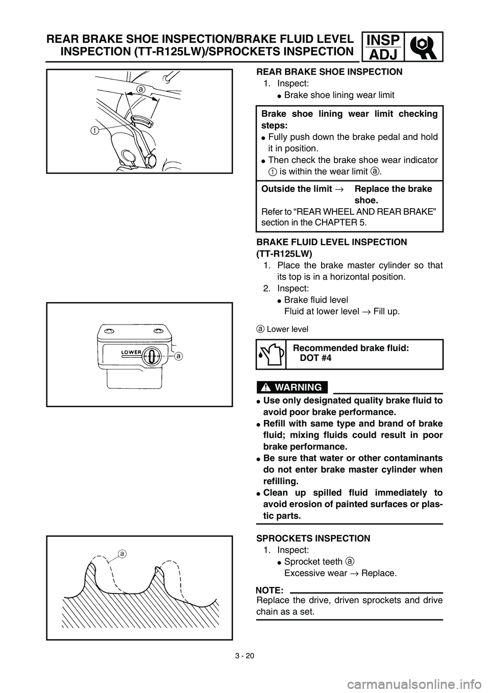
REAR BRAKE SHOE INSPECTION
1. Inspect:
�Brake shoe lining wear limit
BRAKE FLUID LEVEL INSPECTION
(TT-R125LW)
1. Place the brake master cylinder so that
its top is in a horizontal position.
2. Inspect:
�Brake fluid level
Fluid at lower level → Fill up.
aLower level
WARNING
�Use only designated quality brake fluid to
avoid poor brake performance.
�Refill with same type and brand of brake
fluid; mixing fluids could result in poor
brake performance.
�Be sure that water or other contaminants
do not enter brake master cylinder when
refilling.
�Clean up spilled fluid immediately to
avoid erosion of painted surfaces or plas-
tic parts. Brake shoe lining wear limit checking
steps:
�Fully push down the brake pedal and hold
it in position.
�Then check the brake shoe wear indicator
1 is within the wear limit a.
Outside the limit → Replace the brake
shoe.
Refer to “REAR WHEEL AND REAR BRAKE”
section in the CHAPTER 5.
Recommended brake fluid:
DOT #4
SPROCKETS INSPECTION
1. Inspect:
�Sprocket teeth a
Excessive wear → Replace.
NOTE:
Replace the drive, driven sprockets and drive
chain as a set.
REAR BRAKE SHOE INSPECTION/BRAKE FLUID LEVEL
INSPECTION (TT-R125LW)/SPROCKETS INSPECTION
Page 194 of 510
3 - 22
INSP
ADJ
DRIVE CHAIN SLACK ADJUSTMENT
6. Lubricate:
�Drive chain
Drive chain lubricant:
SAE 10W-30 motor oil or suit-
able chain lubricants
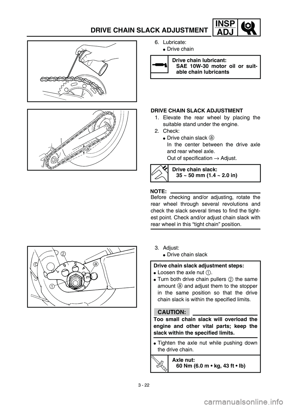
DRIVE CHAIN SLACK ADJUSTMENT
1. Elevate the rear wheel by placing the
suitable stand under the engine.
2. Check:
�Drive chain slack a
In the center between the drive axle
and rear wheel axle.
Out of specification → Adjust.
NOTE:
Before checking and/or adjusting, rotate the
rear wheel through several revolutions and
check the slack several times to find the tight-
est point. Check and/or adjust chain slack with
rear wheel in this “tight chain” position.
Drive chain slack:
35 ~ 50 mm (1.4 ~ 2.0 in)
3. Adjust:
�Drive chain slack
Drive chain slack adjustment steps:
�Loosen the axle nut 1.
�Turn both drive chain pullers 2 the same
amount a and adjust them to the stopper
in the same position so that the drive
chain slack is within the specified limits.
CAUTION:
Too small chain slack will overload the
engine and other vital parts; keep the
slack within the specified limits.
�Tighten the axle nut while pushing down
the drive chain.
T R..
Axle nut:
60 Nm (6.0 m • kg, 43 ft • lb)
Page 196 of 510
3 - 23
INSP
ADJ
FRONT FORK INSPECTION/
REAR SHOCK ABSORBER ASSEMBLY INSPECTION/
REAR SHOCK ABSORBER SPRING PRELOAD ADJUSTMENT
EC36C000
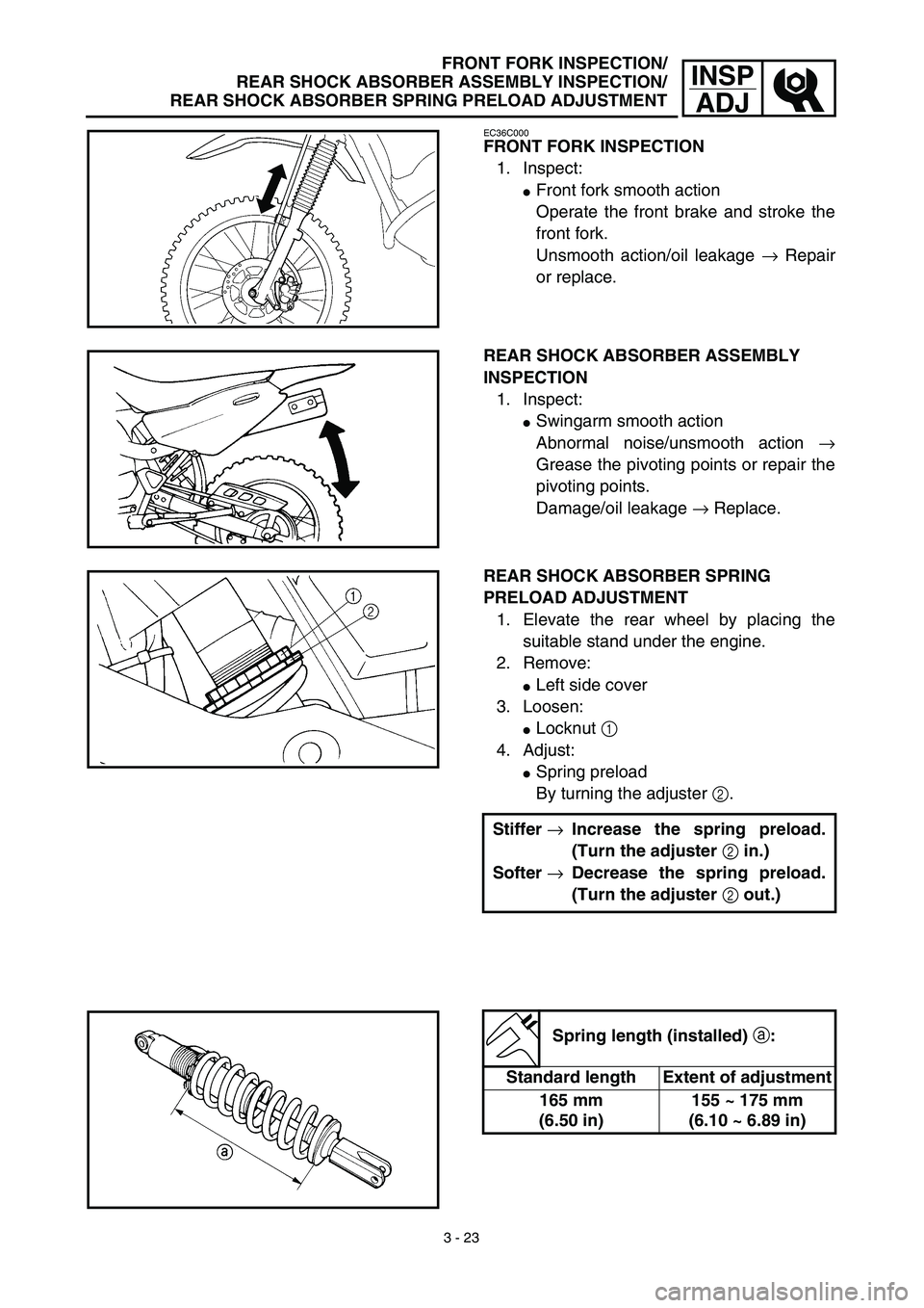
FRONT FORK INSPECTION
1. Inspect:
�Front fork smooth action
Operate the front brake and stroke the
front fork.
Unsmooth action/oil leakage → Repair
or replace.
REAR SHOCK ABSORBER ASSEMBLY
INSPECTION
1. Inspect:
�Swingarm smooth action
Abnormal noise/unsmooth action →
Grease the pivoting points or repair the
pivoting points.
Damage/oil leakage → Replace.
REAR SHOCK ABSORBER SPRING
PRELOAD ADJUSTMENT
1. Elevate the rear wheel by placing the
suitable stand under the engine.
2. Remove:
�Left side cover
3. Loosen:
�Locknut 1
4. Adjust:
�Spring preload
By turning the adjuster 2.
Stiffer →Increase the spring preload.
(Turn the adjuster 2 in.)
Softer →Decrease the spring preload.
(Turn the adjuster 2 out.)
Spring length (installed) a:
Standard length Extent of adjustment
165 mm
(6.50 in)155 ~ 175 mm
(6.10 ~ 6.89 in)
Page 200 of 510
3 - 25
INSP
ADJSPOKES INSPECTION AND TIGHTENING/WHEEL INSPECTION/
STEERING HEAD INSPECTION AND ADJUSTMENT
SPOKES INSPECTION AND TIGHTENING
1. Inspect:
�Spokes 1
Bend/damage → Replace.
Loose spoke → Retighten.
2. Tighten:
�Spokes
NOTE:
Be sure to retighten these spokes before and
after break-in. After a practice check spokes
for looseness.
T R..Front 2 Nm (0.2 m · kg, 1.4 ft · lb)
Rear 3 Nm (0.3 m · kg, 2.2 ft · lb)
EC36T000
WHEEL INSPECTION
1. Inspect:
�Wheel runout
Elevate the wheel and turn it.
Abnormal runout → Replace.
2. Inspect:
�Bearing free play
Exist play → Replace.
STEERING HEAD INSPECTION AND
ADJUSTMENT
1. Elevate the front wheel by placing a suit-
able stand under the engine.
2. Check:
�Steering shaft
Grasp the bottom of the forks and gen-
tly rock the fork assembly back and
forth.
Free play → Adjust steering head.
Page 326 of 510
4 - 59
ENGCDI MAGNETO
REMOVAL POINTS
Rotor
1. Remove:
�Nut (rotor) 1
�Plain washer 2
Use the sheave holder 3.
Sheave holder:
YS-1880-A/90890-01701
2. Remove:
�Rotor 1
Use the flywheel puller 2.
Flywheel puller:
YU-33270-B/90890-01362
EC4L4000
INSPECTION
EC4L4101
CDI magneto
1. Inspect:
�Rotor inner surface a
�Stator outer surface b
Damage → Inspect the crankshaft
runout and crankshaft bearing.
If necessary, replace CDI magneto and/
or stator.
EC4L4200
Woodruff key
1. Inspect:
�Woodruff key 1
Damage → Replace.
EC4L5000
ASSEMBLY AND INSTALLATION
CDI magneto
1. Install:
�Stator 1
�Bolt (stator)
�Lead guide
�Screw (lead guide) 2
�Pickup coil 3
�Bolt (pickup coil)
T R..10 Nm (1.0 m · kg, 7.2 ft · lb)LT
T R..7 Nm (0.7 m · kg, 5.1 ft · lb)LT
T R..10 Nm (1.0 m · kg, 7.2 ft · lb)LT
Page 360 of 510
4 - 76
ENGTRANSMISSION, SHIFT CAM AND SHIFT FORK
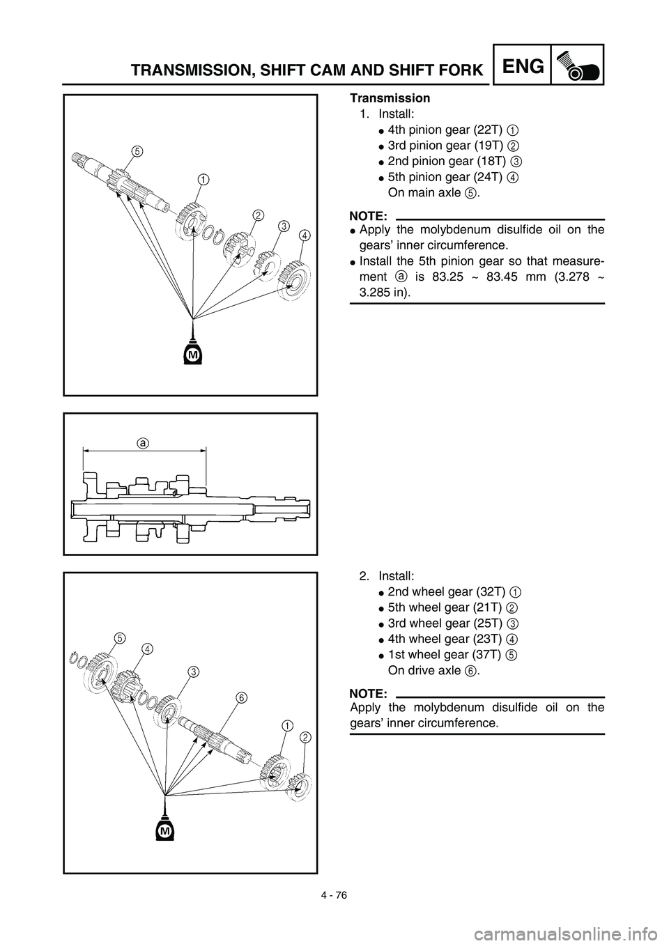
Transmission
1. Install:
�4th pinion gear (22T) 1
�3rd pinion gear (19T) 2
�2nd pinion gear (18T) 3
�5th pinion gear (24T) 4
On main axle 5.
NOTE:
�Apply the molybdenum disulfide oil on the
gears’ inner circumference.
�Install the 5th pinion gear so that measure-
ment a is 83.25 ~ 83.45 mm (3.278 ~
3.285 in).
2. Install:
�2nd wheel gear (32T) 1
�5th wheel gear (21T) 2
�3rd wheel gear (25T) 3
�4th wheel gear (23T) 4
�1st wheel gear (37T) 5
On drive axle 6.
NOTE:
Apply the molybdenum disulfide oil on the
gears’ inner circumference.
Page 364 of 510
4 - 78
ENGTRANSMISSION, SHIFT CAM AND SHIFT FORK
Shift cam and shift fork
1. Install:
�Shift fork 1 (L) 1
�Shift fork 2 (C) 2
�Shift fork 3 (R) 3
NOTE:
�Mesh the shift fork #1 (L) with the 2nd wheel
gear and #3 (R) with the 4th wheel gear on
the drive axle.
�Mesh the shift fork #2 (C) with the 3rd pinion
gear on the main axle.
2. Install:
�Shift cam 1
NOTE:
Apply the engine oil on the shift cam.
3. Install:
�Shift fork guide bar 1 (short) 1
�Shift fork guide bar 2 (long) 2
NOTE:
�Apply the engine oil on the guide bars.
�Be sure the long bar is inserted into the shift
forks #1 and #3 and the short one into #2.
4. Check:
�Shifter operation
�Transmission operation
Unsmooth operation → Repair.