2003 YAMAHA MAJESTY 250 light
[x] Cancel search: lightPage 39 of 116

3-22
INSTRUMENT AND CONTROL FUNCTIONS
3
EAU00330
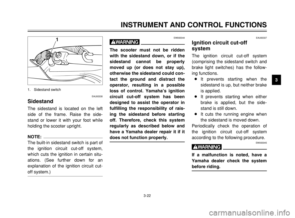
SidestandSidestandThe sidestand is located on the left
side of the frame. Raise the side-
stand or lower it with your foot while
holding the scooter upright.
NOTE:
The built-in sidestand switch is part of
the ignition circuit cut-off system,
which cuts the ignition in certain situ-
ations. (See further down for an
explanation of the ignition circuit cut-
off system.)
1
1. Sidestand switch
EAU00337
Ignition circuit cut-off
system
Ignition circuit cut-off systemThe ignition circuit cut-off system
(comprising the sidestand switch and
brake light switches) has the follow-
ing functions.
8It prevents starting when the
sidestand is up, but neither brake
is applied.
8It prevents starting when either
brake is applied, but the side-
stand is still down.
8It cuts the running engine when
the sidestand is moved down.
Periodically check the operation of
the ignition circuit cut-off system
according to the following procedure.
EW000045
w
If a malfunction is noted, have a
Yamaha dealer check the system
before riding.
EW000044
w
The scooter must not be ridden
with the sidestand down, or if the
sidestand cannot be properly
moved up (or does not stay up),
otherwise the sidestand could con-
tact the ground and distract the
operator, resulting in a possible
loss of control. Yamaha’s ignition
circuit cut-off system has been
designed to assist the operator in
fulfilling the responsibility of rais-
ing the sidestand before starting
off. Therefore, check this system
regularly as described below and
have a Yamaha dealer repair it if it
does not function properly.
5SJ-28199-E1 7/11/02 11:03 AM Page 37
Page 43 of 116

4-2
PRE-OPERATION CHECKS
4
Rear brake•Check operation.
•If soft or spongy, have Yamaha dealer bleed hydraulic system.
•Check fluid level in reservoir.
•If necessary, add recommended brake fluid to specified level.
•Check hydraulic system for leakage.3-12, 6-27–6-30
Throttle grip•Make sure that operation is smooth.
•Check cable free play.
•If necessary, have Yamaha dealer adjust cable free play and lubricate cable and
grip housing.6-23, 6-31
Wheels and tires•Check for damage.
•Check tire condition and tread depth.
•Check air pressure.
•Correct if necessary.6-24–6-27
Brake levers•Make sure that operation is smooth.
•Lubricate lever pivoting points if necessary.3-11–3-12, 6-27, 6-31
Centerstand, sidestand•Make sure that operation is smooth.
•Lubricate pivots if necessary.6-31–6-32
Chassis fasteners•Make sure that all nuts, bolts and screws are properly tightened.
•Tighten if necessary.—
Instruments, lights, signals
and switches•Check operation.
•Correct if necessary.3-2–3-11, 6-37–6-42
Sidestand switch•Check operation of ignition circuit cut-off system.
•If system is defective, have Yamaha dealer check vehicle.3-22–3-23 ITEM CHECKS PAGE
5SJ-28199-E1 7/11/02 11:03 AM Page 41
Page 46 of 116

3
2
1
1. Start switch
2. Front brake lever
3. Rear brake lever
5-1
EAU00372
OPERATION AND IMPORTANT RIDING POINTS
5
EAU01118
w
8 8
Become thoroughly familiar
with all operating controls and
their functions before riding.
Consult a Yamaha dealer
regarding any control or func-
tion that you do not thorough-
ly understand.
8 8
Never start the engine or oper-
ate it in a closed area for any
length of time. Exhaust fumes
are poisonous, and inhaling
them can cause loss of con-
sciousness and death within a
short time. Always make sure
that there is adequate ventila-
tion.
8 8
For safety, always start the
engine with the centerstand
down.
EAU03616*
Starting the engineStarting the engineEC000046
cC
See page 5-4 for engine break-in
instructions prior to operating the
vehicle for the first time.
In order for the ignition circuit cut-off
system to enable starting, the side-
stand must be up.
EW000054
w
8 8
Before starting the engine,
check the function of the igni-
tion circuit cut-off system
according to the procedure
described on page 3-23.
8 8
Never ride with the sidestand
down.
1. Turn the key to “ON” and make
sure that the engine stop switch
is set to “#”.
ECA00068
cC
When the key is turned to “ON”,
the ABS warning light should
come on for a few seconds, and
then go off. If the ABS warning
light does not come on or remains
on, have a Yamaha dealer inspect
the electrical circuit.
5SJ-28199-E1 7/11/02 11:03 AM Page 44
Page 49 of 116

5-4
OPERATION AND IMPORTANT RIDING POINTS
5
EAU04755
Tips for reducing fuel
consumption
Fuel consumption, tips for reducingFuel consumption depends largely on
your riding style. Consider the follow-
ing tips to reduce fuel consumption:
8Avoid high engine speeds during
acceleration.
8Avoid high engine speeds with
no load on the engine.
8Turn the engine off instead of let-
ting it idle for an extended length
of time (e.g., in traffic jams, at
traffic lights or at railroad cross-
ings).
EAU01128
Engine break-inEngine break-inThere is never a more important peri-
od in the life of your engine than the
period between 0 and 1,600 km. For
this reason, you should read the fol-
lowing material carefully.
Since the engine is brand new, do
not put an excessive load on it for the
first 1,600 km. The various parts in
the engine wear and polish them-
selves to the correct operating clear-
ances. During this period, prolonged
full-throttle operation or any condition
that might result in engine overheat-
ing must be avoided.
EAU04590
0–1,000 km
Avoid prolonged operation above
4,000 r/min.
1,000–1,600 km
Avoid prolonged operation above
5,000 r/min.
ECA00138
cC
After 1,000 km of operation, be
sure to replace the engine oil and
final transmission oil.
1,600 km and beyond
The vehicle can now be operated
normally.
ECA00137
cC
8
8
Keep the engine speed below
8,500 r/min.
8 8
If any engine trouble should
occur during the engine break-
in period, immediately have a
Yamaha dealer check the vehi-
cle.
5SJ-28199-E1 7/11/02 11:03 AM Page 47
Page 51 of 116

PERIODIC MAINTENANCE AND MINOR REPAIR
Owner’s tool kit ....................................................6-1
Periodic maintenance and lubrication chart .........6-3
Removing and installing the cowlings and
panel .................................................................6-6
Checking the spark plug ....................................6-12
Engine oil ...........................................................6-14
Final transmission oil .........................................6-18
Coolant ..............................................................6-19
Air filter and V-belt case air filter elements ........6-21
Air flow louver ....................................................6-23
Adjusting the throttle cable free play .................6-23
Adjusting the valve clearance ...........................6-23
Tires ...................................................................6-24
Cast wheels .......................................................6-26
Adjusting the front and rear brake lever
free play ..........................................................6-27
Checking the front and rear brake pads ............6-28
Checking the brake fluid level ............................6-29
Changing the brake fluid ....................................6-30
Checking and lubricating the cables ..................6-30
Checking and lubricating the throttle grip
and cable ........................................................6-31
Lubricating the front and rear brake levers ........6-31Checking and lubricating the centerstand
and sidestand .................................................6-31
Checking the front fork ......................................6-32
Checking the steering ........................................6-33
Checking the wheel bearings ............................6-33
Removing the battery cover ...............................6-34
Battery ...............................................................6-34
Replacing the fuses ...........................................6-36
Replacing a headlight bulb ................................6-37
Replacing a front turn signal light bulb ..............6-39
Replacing a rear turn signal light bulb ...............6-40
Replacing a tail/brake light bulb .........................6-40
Replacing the license plate light bulb ................6-41
Troubleshooting .................................................6-42
Troubleshooting charts ......................................6-43
6
5SJ-28199-E1 7/11/02 11:03 AM Page 49
Page 55 of 116

6-4
PERIODIC MAINTENANCE AND MINOR REPAIR
6
8*Brake hoses•Check for cracks or damage.√√√√ √
•Replace. (See NOTE on page 6-5.)Every 4 years
9
*Wheels•Check runout and for damage.√√√√
10
*Tires•Check tread depth and for damage.
•Replace if necessary.
•Check air pressure.
•Correct if necessary.√√√√ √
11
*Wheel bearings•Check bearing for looseness or damage.√√√√
12
*Steering bearings•Check bearing play and steering for roughness.√√√√√
•Lubricate with lithium-soap-based grease.Every 20,000 km
13
*Chassis fasteners•Make sure that all nuts, bolts and screws are properly tightened.√√√√ √
14 Sidestand, centerstand•Check operation.
•Lubricate.√√√√ √
15
*Sidestand switch•Check operation.√√√√√ √
16
*Front fork•Check operation and for oil leakage.√√√√
17
*Shock absorber
assemblies•Check operation and shock absorbers for oil leakage.√√√√
18
*Carburetor•Adjust engine idling speed.√√√√√ √
19 Engine oil•Change. (See page 3-3 and 6-17 for more information
about the oil change indicator light.)√When the oil change indicator light comes on
(every 3,000 km)
•Check oil level and vehicle for oil leakage.Every 3,000 km√ NO. ITEM CHECK OR MAINTENANCE JOBODOMETER READING (× 1,000 km)
ANNUAL
CHECK
1 10203040
5SJ-28199-E1 7/11/02 11:03 AM Page 53
Page 56 of 116

6-5
PERIODIC MAINTENANCE AND MINOR REPAIR
6
EAU03884
NOTE:
8The air filter needs more frequent service if you are riding in unusually wet or dusty areas.
8Hydraulic brake service
9Regularly check and, if necessary, correct the brake fluid level.
9Every two years replace the internal components of the brake master cylinders and calipers, and change the
brake fluid.
9Replace the brake hoses every four years and if cracked or damaged.
20*Engine oil strainer•Clean.√
21
*Cooling system•Check coolant level and vehicle for coolant leakage.√√√√ √
•Change.Every 3 years
22 Final transmission oil•Check vehicle for oil leakage.√√ √
•Change.√√√
23
*V-belt•Replace.Every 20,000 km
24
*Front and rear brake
switches•Check operation.√√√√√ √
25 Moving parts and cables•Lubricate.√√√√ √
26
*Throttle grip housing
and cable•Check operation and free play.
•Adjust the throttle cable free play if necessary.
•Lubricate the throttle grip housing and cable.√√√√ √
27
*Lights, signals and
switches•Check operation.
•Adjust headlight beam.√√√√√ √ NO. ITEM CHECK OR MAINTENANCE JOBODOMETER READING (× 1,000 km)
ANNUAL
CHECK
1 10203040
5SJ-28199-E1 7/11/02 11:03 AM Page 54
Page 59 of 116

6-8
PERIODIC MAINTENANCE AND MINOR REPAIR
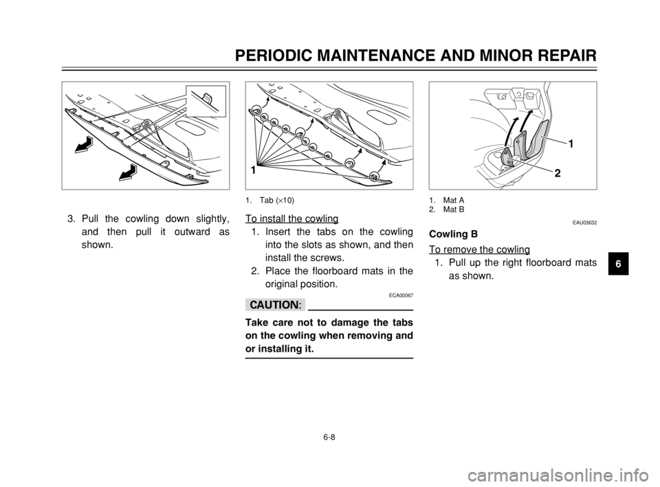
6 3. Pull the cowling down slightly,
and then pull it outward as
shown.
EAU03632
Cowling BCowling *To remove the cowling
1. Pull up the right floorboard mats
as shown.
1
2
1. Mat A
2. Mat B
To install the cowling
1. Insert the tabs on the cowling
into the slots as shown, and then
install the screws.
2. Place the floorboard mats in the
original position.
ECA00067
cC
Take care not to damage the tabs
on the cowling when removing and
or installing it.
1
1. Tab (×10)
5SJ-28199-E1 7/11/02 11:03 AM Page 57