2003 YAMAHA MAJESTY 250 steering
[x] Cancel search: steeringPage 16 of 116

2-3
DESCRIPTION
2
1
23
46578910
11
12 13
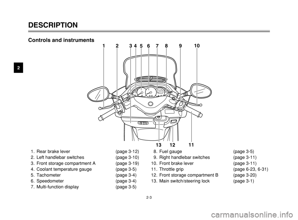
Controls and instruments
1. Rear brake lever (page 3-12)
2. Left handlebar switches (page 3-10)
3. Front storage compartment A (page 3-19)
4. Coolant temperature gauge (page 3-5)
5. Tachometer (page 3-4)
6. Speedometer (page 3-4)
7. Multi-function display (page 3-5)8. Fuel gauge (page 3-5)
9. Right handlebar switches (page 3-11)
10. Front brake lever (page 3-11)
11. Throttle grip (page 6-23, 6-31)
12. Front storage compartment B (page 3-20)
13. Main switch/steering lock (page 3-1)
5SJ-28199-E1 7/11/02 11:03 AM Page 14
Page 17 of 116

INSTRUMENT AND CONTROL FUNCTIONS
Main switch/steering lock ...................................................................3-1
Indicator and warning lights ...............................................................3-2
Speedometer .....................................................................................3-4
Tachometer .......................................................................................3-4
Fuel gauge .........................................................................................3-5
Coolant temperature gauge ...............................................................3-5
Multi-function display .........................................................................3-5
Anti-theft alarm (optional) ................................................................3-10
Handlebar switches .........................................................................3-10
Front brake lever .............................................................................3-11
Rear brake lever ..............................................................................3-12
ABS .................................................................................................3-13
Fuel tank cap ...................................................................................3-15
Fuel ..................................................................................................3-16
Catalytic converter ...........................................................................3-17
Rider seat ........................................................................................3-18
Adjusting the rider seat ....................................................................3-18
Storage compartments ....................................................................3-19
Adjusting the shock absorber assemblies .......................................3-21
Sidestand .........................................................................................3-22
Ignition circuit cut-off system ...........................................................3-22
3
5SJ-28199-E1 7/11/02 11:03 AM Page 15
Page 18 of 116

3-1
EAU00029
Main switch/steering lockMain switch/steering lockThe main switch/steering lock con-
trols the ignition and lighting systems,
and is used to lock the steering. The
various positions are described
below.
EAU04580
ON
All electrical circuits are supplied with
power; the meter lighting, taillight,
license plate light and auxiliary light
come on, and the engine can be
started. The key cannot be removed.
EAU00027
INSTRUMENT AND CONTROL FUNCTIONS
3IGNITIONP
LOCK
ON
OFF
OPEN
PUSH
PUSH
NOTE:
The headlight comes on automatical-
ly when the engine is started and
stays on until the key is turned to
“OFF” or the sidestand is moved
down.
EAU00038
OFF
All electrical systems are off. The key
can be removed.
EAU00040
LOCK
The steering is locked, and all electri-
cal systems are off. The key can be
removed.To lock the steering
1. Turn the handlebars all the way
to the left.
2. Push the key in from the “OFF”
position, and then turn it to
“LOCK” while still pushing it.
3. Remove the key.
To unlock the steering
Push the key in, and then turn it to
“OFF” while still pushing it.
EW000016
w
Never turn the key to “OFF” or
“LOCK” while the scooter is mov-
ing, otherwise the electrical sys-
tems will be switched off, which
may result in loss of control or an
accident. Make sure that the scoot-
er is stopped before turning the
key to “OFF” or “LOCK”.
5SJ-28199-E1 7/11/02 11:03 AM Page 16
Page 19 of 116

3-2
INSTRUMENT AND CONTROL FUNCTIONS
3
EAU03733
.(Parking)
The steering is locked, and the tail-
light, license light and auxiliary light
are on, but all other electrical sys-
tems are off. The key can be
removed.
To turn the main switch to “
.”:
1. Turn the key to “LOCK”.
2. Slightly turn the key counter-
clockwise until it stops.
3. While still turning the key coun-
terclockwise, push it in until it
snaps into place.
ECA00043
cC
Do not use the parking position for
an extended length of time, other-
wise the battery may discharge.
EAU04901
ABS warning light “”ABS warning lightECA00019
cC
If the ABS warning light comes on
or flashes while riding, the ABS
may be defective. If this occurs,
have a Yamaha dealer check the
electrical circuit.
See page 3-13 for an explanation of
the ABS.
The electrical circuit of the warning
light can be checked by setting the
engine stop switch to “#” and turning
the key to “ON”.
The warning light should come on for
a few seconds, and then go off. If the
warning light does not come on or
remains on, have a Yamaha dealer
check the electrical circuit.
EAU03034
Indicator and warning lightsIndicator and warning lightsEAU04121
Turn signal indicator lights “4”
and “6”
Turn signal indicator lightsThe corresponding indicator light
flashes when the turn signal switch is
pushed to the left or right.
13
45
2
1. Left turn signal indicator light “4”
2. ABS warning light “”
3. High beam indicator light “&”
4. Oil change indicator light “
7”
5. Right turn signal indicator light “6”
5SJ-28199-E1 7/11/02 11:03 AM Page 17
Page 51 of 116

PERIODIC MAINTENANCE AND MINOR REPAIR
Owner’s tool kit ....................................................6-1
Periodic maintenance and lubrication chart .........6-3
Removing and installing the cowlings and
panel .................................................................6-6
Checking the spark plug ....................................6-12
Engine oil ...........................................................6-14
Final transmission oil .........................................6-18
Coolant ..............................................................6-19
Air filter and V-belt case air filter elements ........6-21
Air flow louver ....................................................6-23
Adjusting the throttle cable free play .................6-23
Adjusting the valve clearance ...........................6-23
Tires ...................................................................6-24
Cast wheels .......................................................6-26
Adjusting the front and rear brake lever
free play ..........................................................6-27
Checking the front and rear brake pads ............6-28
Checking the brake fluid level ............................6-29
Changing the brake fluid ....................................6-30
Checking and lubricating the cables ..................6-30
Checking and lubricating the throttle grip
and cable ........................................................6-31
Lubricating the front and rear brake levers ........6-31Checking and lubricating the centerstand
and sidestand .................................................6-31
Checking the front fork ......................................6-32
Checking the steering ........................................6-33
Checking the wheel bearings ............................6-33
Removing the battery cover ...............................6-34
Battery ...............................................................6-34
Replacing the fuses ...........................................6-36
Replacing a headlight bulb ................................6-37
Replacing a front turn signal light bulb ..............6-39
Replacing a rear turn signal light bulb ...............6-40
Replacing a tail/brake light bulb .........................6-40
Replacing the license plate light bulb ................6-41
Troubleshooting .................................................6-42
Troubleshooting charts ......................................6-43
6
5SJ-28199-E1 7/11/02 11:03 AM Page 49
Page 55 of 116

6-4
PERIODIC MAINTENANCE AND MINOR REPAIR
6
8*Brake hoses•Check for cracks or damage.√√√√ √
•Replace. (See NOTE on page 6-5.)Every 4 years
9
*Wheels•Check runout and for damage.√√√√
10
*Tires•Check tread depth and for damage.
•Replace if necessary.
•Check air pressure.
•Correct if necessary.√√√√ √
11
*Wheel bearings•Check bearing for looseness or damage.√√√√
12
*Steering bearings•Check bearing play and steering for roughness.√√√√√
•Lubricate with lithium-soap-based grease.Every 20,000 km
13
*Chassis fasteners•Make sure that all nuts, bolts and screws are properly tightened.√√√√ √
14 Sidestand, centerstand•Check operation.
•Lubricate.√√√√ √
15
*Sidestand switch•Check operation.√√√√√ √
16
*Front fork•Check operation and for oil leakage.√√√√
17
*Shock absorber
assemblies•Check operation and shock absorbers for oil leakage.√√√√
18
*Carburetor•Adjust engine idling speed.√√√√√ √
19 Engine oil•Change. (See page 3-3 and 6-17 for more information
about the oil change indicator light.)√When the oil change indicator light comes on
(every 3,000 km)
•Check oil level and vehicle for oil leakage.Every 3,000 km√ NO. ITEM CHECK OR MAINTENANCE JOBODOMETER READING (× 1,000 km)
ANNUAL
CHECK
1 10203040
5SJ-28199-E1 7/11/02 11:03 AM Page 53
Page 84 of 116

6-33
PERIODIC MAINTENANCE AND MINOR REPAIR
6
EAU00794
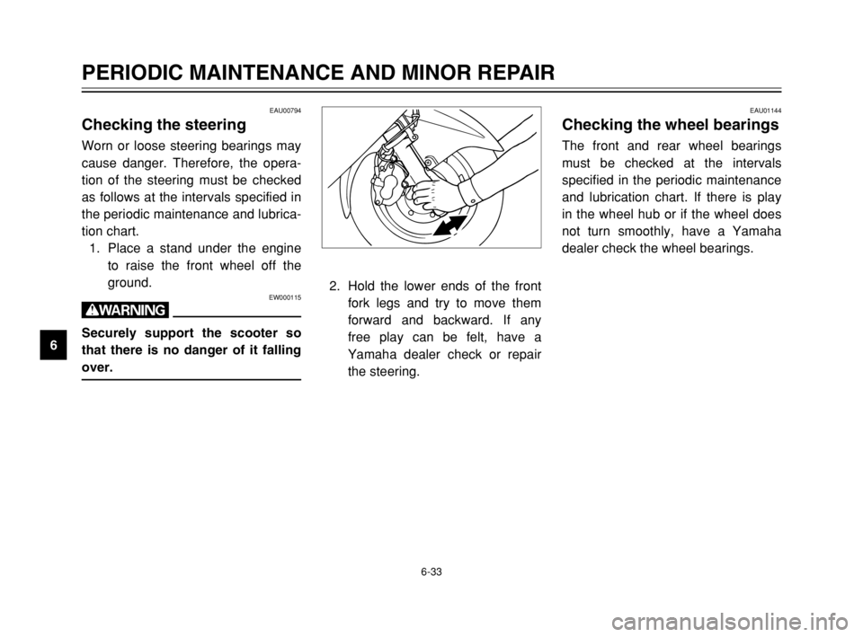
Checking the steeringSteering, checkingWorn or loose steering bearings may
cause danger. Therefore, the opera-
tion of the steering must be checked
as follows at the intervals specified in
the periodic maintenance and lubrica-
tion chart.
1. Place a stand under the engine
to raise the front wheel off the
ground.
EW000115
w
Securely support the scooter so
that there is no danger of it falling
over.
EAU01144
Checking the wheel bearingsWheel bearings, checkingThe front and rear wheel bearings
must be checked at the intervals
specified in the periodic maintenance
and lubrication chart. If there is play
in the wheel hub or if the wheel does
not turn smoothly, have a Yamaha
dealer check the wheel bearings.
2. Hold the lower ends of the front
fork legs and try to move them
forward and backward. If any
free play can be felt, have a
Yamaha dealer check or repair
the steering.
5SJ-28199-E1 7/11/02 11:03 AM Page 82
Page 112 of 116

INDEX
D
Display, multi-function ............................3-5
E
Engine break-in ......................................5-4
Engine oil ..............................................6-14
F
Final transmission oil ............................6-18
Front and rear brake lever free play,
adjusting ...........................................6-27
Front and rear brake pads, checking ....6-28
Front fork, checking ..............................6-32
Fuel ......................................................3-16
Fuel consumption, tips for reducing .......5-4
Fuel gauge .............................................3-5
Fuel tank cap ........................................3-15
Fuses, replacing ...................................6-36
H
Handlebar switches ..............................3-10
Dimmer switch ..................................3-10
Engine stop switch ............................3-11
Horn switch .......................................3-10
Pass switch .......................................3-10
Start switch .......................................3-11
Turn signal switch .............................3-10
Headlight bulb, replacing ......................6-37I
Identification numbers ............................9-1
Ignition circuit cut-off system ................3-22
Indicator and warning lights ....................3-2
ABS warning light ................................3-2
High beam indicator light .....................3-3
Oil change indicator light .....................3-3
Turn signal indicator lights ...................3-2
K
Key identification number .......................9-1
L
License plate light bulb, replacing ........6-41
M
Main switch/steering lock .......................3-1
Model label .............................................9-2
P
Parking ...................................................5-5
Part locations ..........................................2-1
Periodic maintenance and lubrication
chart .....................................................6-3
Pre-operation check list ..........................4-1
R
Rider seat .............................................3-18
Rider seat, adjusting .............................3-18A
ABS ......................................................3-13
Acceleration and deceleration ................5-3
Air filter and V-belt case air filter
elements, cleaning ............................6-21
Air flow louver .......................................6-23
Anti-theft alarm (optional) .....................3-10
B
Battery ..................................................6-34
Battery cover removal ..........................6-34
Brake fluid level, checking ....................6-29
Brake fluid, changing ............................6-30
Brake lever, front ..................................3-11
Brake lever, rear ...................................3-12
Brake levers, lubricating .......................6-31
Braking ...................................................5-3
C
Cables, checking and lubricating ..........6-30
Care ........................................................7-1
Catalytic converter ................................3-17
Centerstand and sidestand, checking
and lubricating ..................................6-31
Conversion table ....................................8-5
Coolant .................................................6-19
Coolant temperature gauge ....................3-5
Cowlings and panel, removing and
installing ..............................................6-6
5SJ-28199-E1 7/11/02 11:03 AM Page 110