Page 71 of 2234
010LF±01
��
�
�
�
�
D25016
±
INTRODUCTION REPAIR INSTRUCTION
01±5
AVENSIS REPAIR MANUAL (RM1018E)
REPAIR INSTRUCTION
PRECAUTION
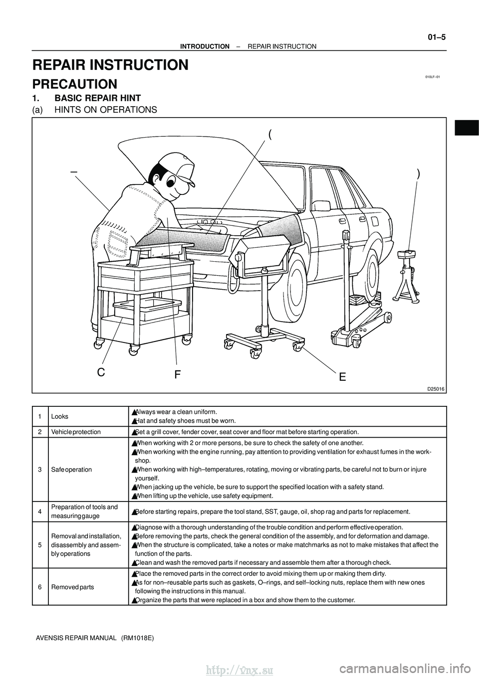
1. BASIC REPAIR HINT
(a) HINTS ON OPERATIONS
1Looks�Always wear a clean uniform.
� Hat and safety shoes must be worn.
2Vehicle protection�Set a grill cover, fender cover, seat cover and floor mat before starting operation.
3Safe operation
�When working with 2 or more persons, be sure to check the safety of one \
another.
� When working with the engine running, pay attention to providing ventila\
tion for exhaust fumes in the work-
shop.
� When working with high±temperatures, rotating, moving or vibrating pa\
rts, be careful not to burn or injure
yourself.
� When jacking up the vehicle, be sure to support the specified location w\
ith a safety stand.
� When lifting up the vehicle, use safety equipment.
4Preparation of tools and
measuring gauge�Before starting repairs, prepare the tool stand, SST, gauge, oil, shop rag and parts for replacement.
5
Removal and installation,
disassembly and assem-
bly operations
�Diagnose with a thorough understanding of the trouble condition and perf\
orm effective operation.
� Before removing the parts, check the general condition of the assembly, and for deformation and damage.
� When the structure is complicated, take a notes or make matchmarks as no\
t to make mistakes that affect the
function of the parts.
� Clean and wash the removed parts if necessary and assemble them after a \
thorough check.
6Removed parts
�Place the removed parts in the correct order to avoid mixing them up or \
making them dirty.
� As for non±reusable parts such as gaskets, O±rings, and self±lo\
cking nuts, replace them with new ones
following the instructions in this manual.
� Organize the parts that were replaced in a box and show them to the cust\
omer.
http://vnx.su
Page 109 of 2234
02±30
±
PREPARATION DRIVE SHAFT / PROPELLER SHAFT
AVENSIS REPAIR MANUAL (RM1018E)
09610±20012Pitman Arm PullerREAR AXLE CARRIER SUB±ASSY
LH
09628±10011Ball Joint PullerREAR AXLE LH HUB BOLT
FRONT AXLE LH HUB BOLT
09628±62011Boll Joint PullerFRONT AXLE HUB SUB±ASSY LH
REAR AXLE CARRIER SUB±ASSY
LH
FRONT DRIVE SHAFT
09710±04081BaseFRONT DRIVE SHAFT
09718±00010Shoe Hold Down Spring DriverREAR AXLE CARRIER SUB±ASSY
LH
09726±40010Lower Control Shaft Bearing
ReplacerFRONT DRIVE SHAFT
09930±00010Drive Shaft Nut ChiselFRONT AXLE HUB SUB±ASSY LH
FRONT DRIVE SHAFT
09950±00020Bearing RemoverFRONT DRIVE SHAFT
09950±40011Puller B SetFRONT AXLE HUB SUB±ASSY LH
(09951±04020)Hanger 200FRONT AXLE HUB SUB±ASSY LH
(09952±04010)Slide ArmFRONT AXLE HUB SUB±ASSY LH
(09953±04030)Center Bolt 200FRONT AXLE HUB SUB±ASSY LH
(09954±04010)Arm 25FRONT AXLE HUB SUB±ASSY LH
http://vnx.su
Page 143 of 2234
022JT±01
±
PREPARATION PARKING BRAKE
02±35
AVENSIS REPAIR MANUAL (RM1018E)
PARKING BRAKE
PREPARATION
SST
09718±00010Shoe Hold Down Spring DriverPARKING BRAKE ASSY
PARKING BRAKE CABLE ASSY NO.3
Recomended Tools
09070±20010Moulding RemoverPARKING BRAKE CABLE ASSY NO.1
PARKING BRAKE LEVER SUB±ASSY
Equipment
Torque wrench
Slide calipers
http://vnx.su
Page 213 of 2234
031FV±01
±
SERVICE SPECIFICATIONS PARKING BRAKE
03±43
AVENSIS REPAIR MANUAL (RM1018E)
PARKING BRAKE
SERVICE DATA
Parking brake lever travel at 196 N (20 kgf, 44.1 lbf):6 ± 9 clicks
Rear brake disc inside diameter Standard
Maximum173 mm (6.81 in.)
174 mm (6.85 in.)
Parking brake shoe lining thickness Standard
Maximum3.5 mm (0.138 in.)
1.0 mm (0.039 in.)
http://vnx.su
Page 1064 of 2234
30093±02
������F45576
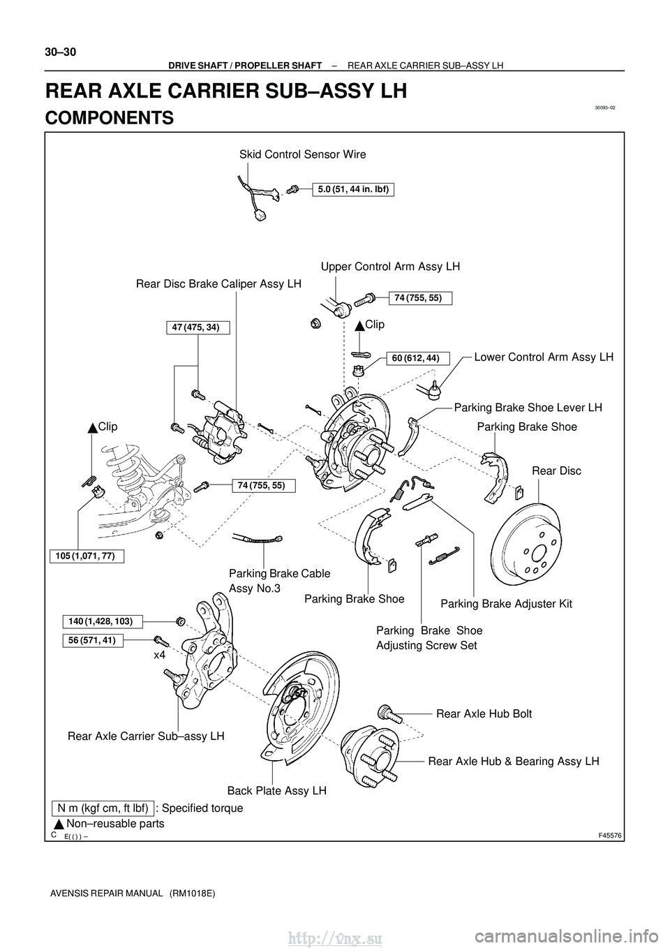
Skid Control Sensor Wire
5.0 (51, 44 in.�lbf)
Upper Control Arm Assy LH
�Clip
74 (755, 55)
60 (612, 44)Lower Control Arm Assy LH
Parking Brake Shoe
Rear Disc
47 (475, 34)
Rear Disc Brake Caliper Assy LH
� Clip
105 (1,071, 77)
Parking Brake Shoe
140 (1,428, 103)
56 (571, 41)
Rear Axle Carrier Sub±assy LH
Rear Axle Hub & Bearing Assy LH
Rear Axle Hub Bolt
x4
N
�m (kgf� cm, ft�lbf) : Specified torque
� Non±reusable parts Parking Brake Cable
Assy No.3
Parking Brake Shoe
Adjusting Screw Set
Parking Brake Adjuster Kit
Parking Brake Shoe Lever LH
74 (755, 55)
Back Plate Assy LH
30±30
±
DRIVE SHAFT / PROPELLER SHAFT REAR AXLE CARRIER SUB±ASSY LH
AVENSIS REPAIR MANUAL (RM1018E)
REAR AXLE CARRIER SUB±ASSY LH
COMPONENTS
http://vnx.su
Page 1065 of 2234
300JZ±01
������F45267
F44818
������F45752
SST
±
DRIVE SHAFT / PROPELLER SHAFT REAR AXLE CARRIER SUB±ASSY LH
30±31
AVENSIS REPAIR MANUAL (RM1018E)
REPLACEMENT
HINT:
Replace the RH side by the same procedures as the LH side.
1. INSPECT REAR AXLE CARRIER SUB±ASSY LH
(a) Check that there is no looseness on the ball joint by shaking the lower arm up and down with a force
of 294 N (30kgf, 66 lbf).
2. REMOVE REAR WHEEL
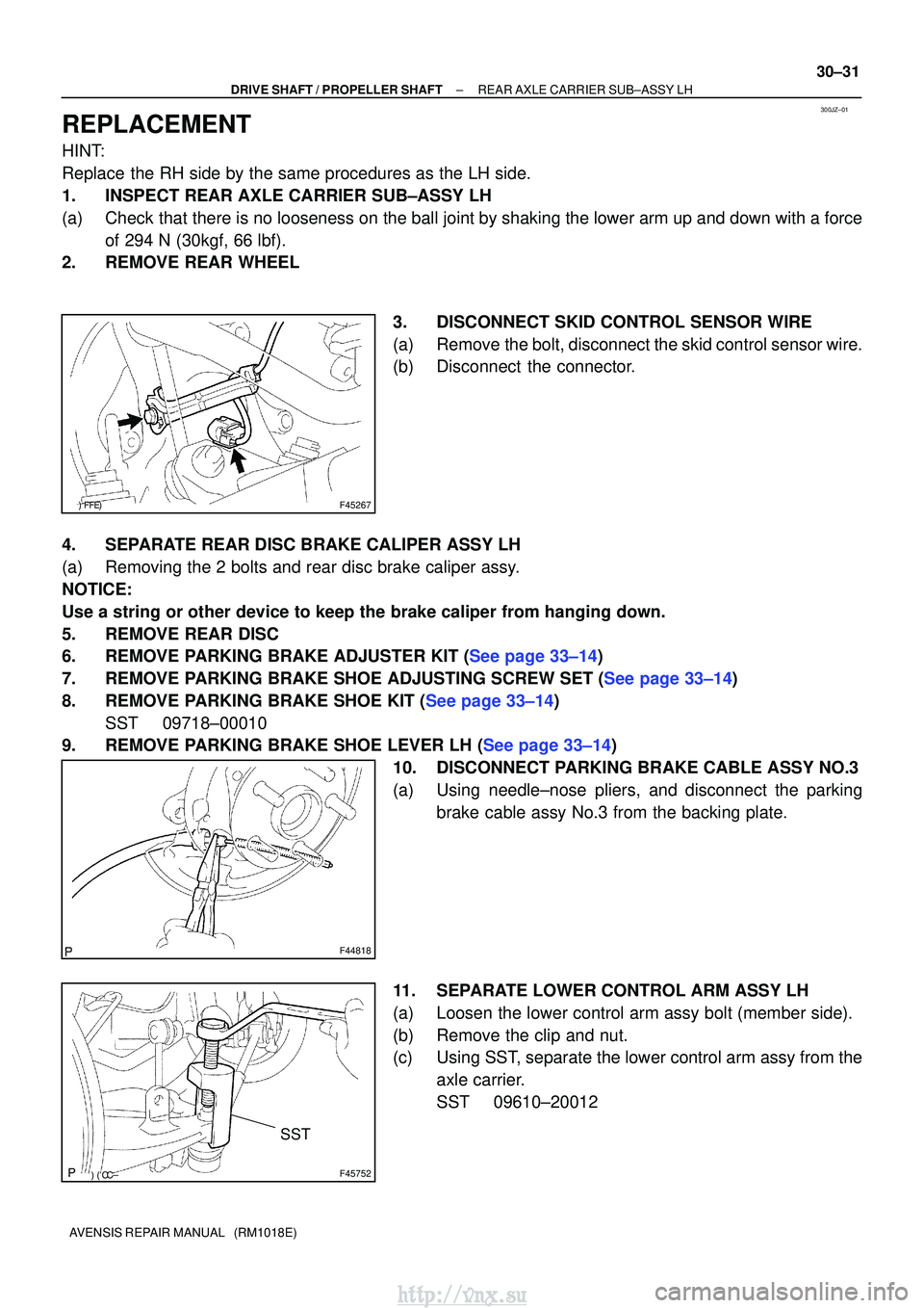
3. DISCONNECT SKID CONTROL SENSOR WIRE
(a) Remove the bolt, disconnect the skid control sensor wire.
(b) Disconnect the connector.
4. SEPARATE REAR DISC BRAKE CALIPER ASSY LH
(a) Removing the 2 bolts and rear disc brake caliper assy.
NOTICE:
Use a string or other device to keep the brake caliper from hanging down\
.
5. REMOVE REAR DISC
6.REMOVE PARKING BRAKE ADJUSTER KIT (See page 33±14)
7.REMOVE PARKING BRAKE SHOE ADJUSTING SCREW SET (See page 33±14)
8.REMOVE PARKING BRAKE SHOE KIT (See page 33±14) SST 09718±00010
9.REMOVE PARKING BRAKE SHOE LEVER LH (See page 33±14)
10. DISCONNECT PARKING BRAKE CABLE ASSY NO.3
(a) Using needle±nose pliers, and disconnect the parkingbrake cable assy No.3 from the backing plate.
11. SEPARATE LOWER CONTROL ARM ASSY LH
(a) Loosen the lower control arm assy bolt (member side).
(b) Remove the clip and nut.
(c) Using SST, separate the lower control arm assy from the axle carrier.
SST 09610±20012
http://vnx.su
Page 1068 of 2234
G21543
F44820
������F45267
30±34
±
DRIVE SHAFT / PROPELLER SHAFTREAR AXLE CARRIER SUB±ASSY LH
AVENSIS REPAIR MANUAL (RM1018E)
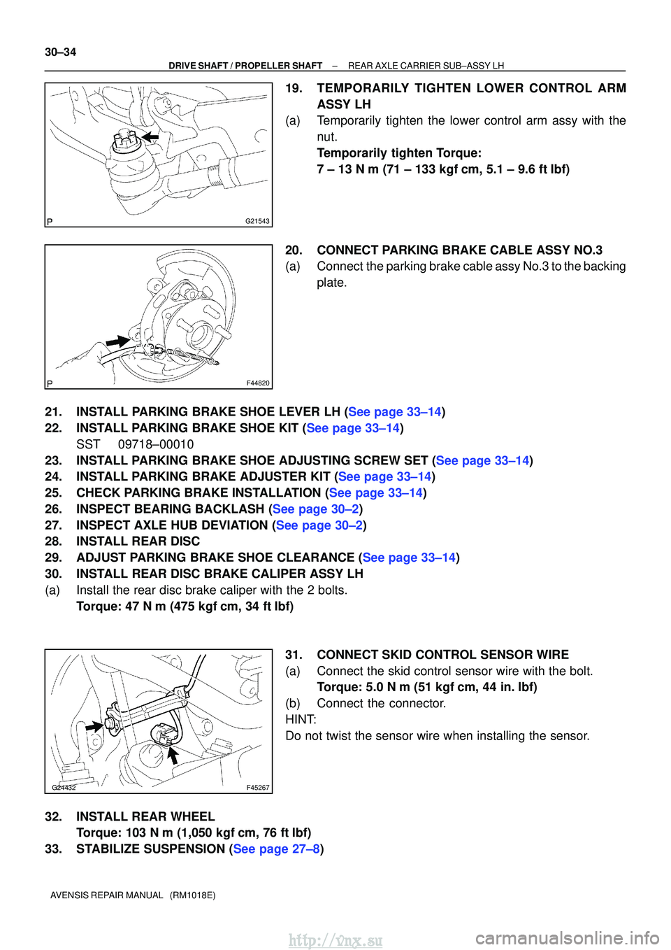
19.TEMPORARILY TIGHTEN LOWER CONTROL ARM ASSY LH
(a)Temporarily tighten the lower control arm assy with the
nut.
Temporarily tighten Torque:
7 ± 13 N�m (71 ± 133 kgf �cm, 5.1 ± 9.6 ft�lbf)
20.CONNECT PARKING BRAKE CABLE ASSY NO.3
(a)Connect the parking brake cable assy No.3 to the backing plate.
21.INSTALL PARKING BRAKE SHOE LEVER LH (See page 33±14)
22.INSTALL PARKING BRAKE SHOE KIT (See page 33±14) SST 09718±00010
23.INSTALL PARKING BRAKE SHOE ADJUSTING SCREW SET (See page 33±14)
24.INSTALL PARKING BRAKE ADJUSTER KIT (See page 33±14)
25.CHECK PARKING BRAKE INSTALLATION (See page 33±14)
26.INSPECT BEARING BACKLASH (See page 30±2)
27.INSPECT AXLE HUB DEVIATION (See page 30±2)
28. INSTALL REAR DISC
29.ADJUST PARKING BRAKE SHOE CLEARANCE (See page 33±14)
30. INSTALL REAR DISC BRAKE CALIPER ASSY LH
(a) Install the rear disc brake caliper with the 2 bolts. Torque: 47 N �m (475 kgf� cm, 34 ft�lbf)
31. CONNECT SKID CONTROL SENSOR WIRE
(a) Connect the skid control sensor wire with the bolt. Torque: 5.0 N �m (51 kgf �cm, 44 in. �lbf)
(b) Connect the connector.
HINT:
Do not twist the sensor wire when installing the sensor.
32. INSTALL REAR WHEEL Torque: 103 N� m (1,050 kgf�cm, 76 ft �lbf)
33.STABILIZE SUSPENSION (See page 27±8)
http://vnx.su
Page 1113 of 2234
320GE±03
G23180
� Gasket
Flexible Hose
30 (306, 22)
Disc Brake Cylinder
Assy Rear LH
Disc Brake
Pad Kit Rear
�
Non±reusable part
N�m (kgf� cm, ft�lbf) : Specified torque
Lithium soap base glycol grease
Rear Disc Brake
Bush Dust Boot
Rear Disc Brake
Pad Support Plate No.1
Rear Disc Brake
Cylinder Mounting LH
RearDisc
Brake Piston
Cylinder Boot
�
Piston Seal
Rear Disc Brake
Cylinder Slide Pin (No.2)
Bleeder Plug Cap
Rear Disc Brake
Bleeder Plug
Rear Disc Brake
Cylinder Slide Bush
Rear Disc Brake
Cylinder Slide Pin (No.1)
Rear Disc Brake
Bush Dust Boot
Rear Disc
Parking Brake Shoe
Adjusting Hole Plug
47 (475, 34)
30 (306, 22)
47 (475, 34)
29 (296, 21)
10 (102, 7)
Rear Disc Brake
Pad Support Plate No.2
Union Bolt
�
�
�
Bolt
�
Bolt
32±46
±
BRAKE REAR BRAKE
AVENSIS REPAIR MANUAL (RM1018E)
REAR DISC BRAKE
COMPONENTS
http://vnx.su