Page 430 of 2234
13070±01
A79168
A80112
A80113
A64328
2 to 7 mm0 to 5 mm
13±18
±
INTAKEINTERCOOLER ASSY(1CD±FTV)
AVENSIS REPAIR MANUAL (RM1018E)
INTERCOOLER ASSY(1CD±FTV)
REPLACEMENT
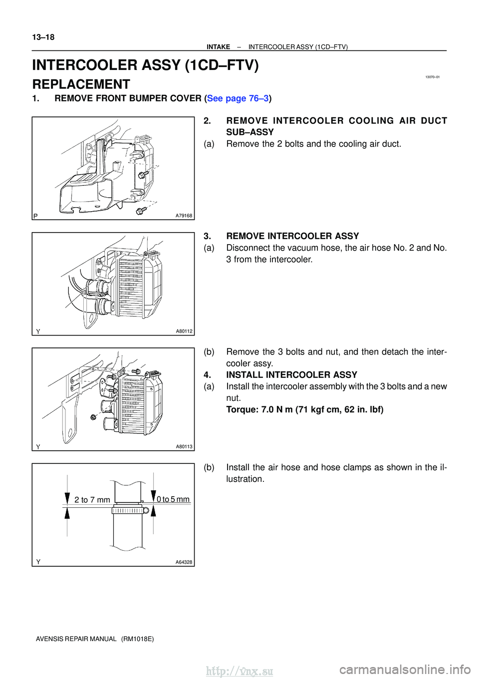
1.REMOVE FRONT BUMPER COVER (See page 76±3) 2. REMOVE INTERCOOLER COOLING AIR DUCTSUB±ASSY
(a) Remove the 2 bolts and the cooling air duct.
3. REMOVE INTERCOOLER ASSY
(a) Disconnect the vacuum hose, the air hose No. 2 and No. 3 from the intercooler.
(b) Remove the 3 bolts and nut, and then detach the inter- cooler assy.
4. INSTALL INTERCOOLER ASSY
(a) Install the intercooler assembly with the 3 bolts and a new nut.
Torque: 7.0 N� m (71 kgf�cm, 62 in. �lbf)
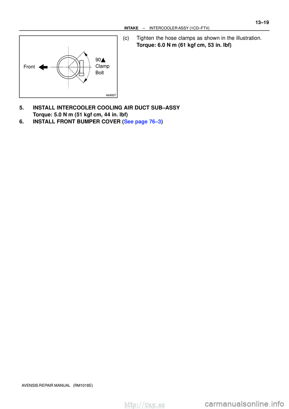
(b) Install the air hose and hose clamps as shown in the il- lustration.
http://vnx.su
Page 431 of 2234
A64007
Front90�
Clamp
Bolt
±
INTAKEINTERCOOLER ASSY(1CD±FTV)
13±19
AVENSIS REPAIR MANUAL (RM1018E)
(c)Tighten the hose clamps as shown in the illustration.
Torque: 6.0 N �m (61 kgf�cm, 53 in. �lbf)
5.INSTALL INTERCOOLER COOLING AIR DUCT SUB±ASSY Torque: 5.0 N �m (51 kgf�cm, 44 in. �lbf)
6.INSTALL FRONT BUMPER COVER (See page 76±3)
http://vnx.su
Page 438 of 2234
A79440
Union To Connector Tube Hose
Fuel Filter Assy
Vacuum Reservoir Sub±assy
43 (440, 32)
43 (440, 32)
�
Gasket
� Gasket Compression Spring
Floor Panel Brace Front
Exhaust Pipe Assy Front
Compression Spring
N´m (kgf´cm, ft´lbf) : Specified torque
� Non±reusable part
Intercooler Air Hose
� Gasket
7.5 (76, 66 in.� lbf)
Exhaust Pipe Assy
30 (302, 22)
7.5 (76, 66 in.�lbf)
Heater Bracket
Heater Pump Assy25 (255, 18)
25 (255, 18)
7.5 (76, 66 in. �lbf)
18 (178, 13)
7.5 (76, 66 in. �lbf)
w/ Cold Area:
w/ Cold Area:
w/ Cold Area:
8.3 (85, 73 in.� lbf)
Air Tube No. 1
±
INTAKE TURBOCHARGER SUB±ASSY (1CD±FTV)
13±9
AVENSIS REPAIR MANUAL (RM1018E)
http://vnx.su
Page 440 of 2234
1306Z±01
A79155
A80093
A79158
±
INTAKETURBOCHARGER SUB±ASSY(1CD±FTV)
13±11
AVENSIS REPAIR MANUAL (RM1018E)
REPLACEMENT
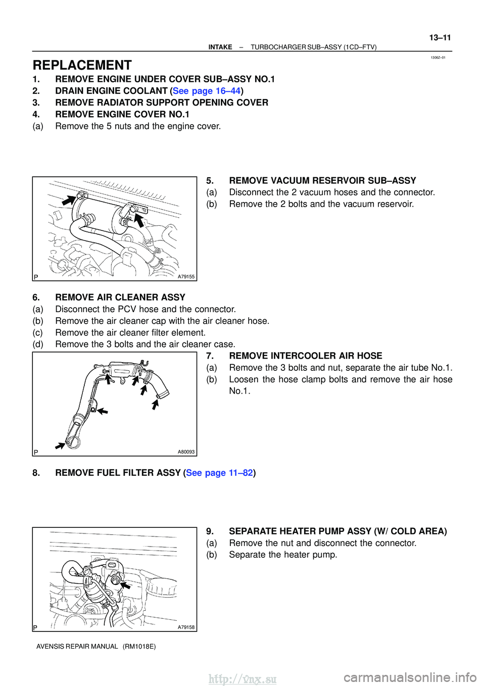
1.REMOVE ENGINE UNDER COVER SUB±ASSY NO.1
2.DRAIN ENGINE COOLANT(See page 16±44)
3.REMOVE RADIATOR SUPPORT OPENING COVER
4.REMOVE ENGINE COVER NO.1
(a)Remove the 5 nuts and the engine cover.
5.REMOVE VACUUM RESERVOIR SUB±ASSY
(a)Disconnect the 2 vacuum hoses and the connector.
(b)Remove the 2 bolts and the vacuum reservoir.
6.REMOVE AIR CLEANER ASSY
(a)Disconnect the PCV hose and the connector.
(b)Remove the air cleaner cap with the air cleaner hose.
(c)Remove the air cleaner filter element.
(d)Remove the 3 bolts and the air cleaner case. 7.REMOVE INTERCOOLER AIR HOSE
(a)Remove the 3 bolts and nut, separate the air tube No.1.
(b)Loosen the hose clamp bolts and remove the air hoseNo.1.
8.REMOVE FUEL FILTER ASSY(See page 11±82) 9. SEPARATE HEATER PUMP ASSY (W/ COLD AREA)
(a) Remove the nut and disconnect the connector.
(b) Separate the heater pump.
http://vnx.su
Page 446 of 2234
A64328
2 to 7 mm0 to 2 mm
A78274
Upward90�
Clamp
Bolt
±
INTAKETURBOCHARGER SUB±ASSY(1CD±FTV)
13±17
AVENSIS REPAIR MANUAL (RM1018E)
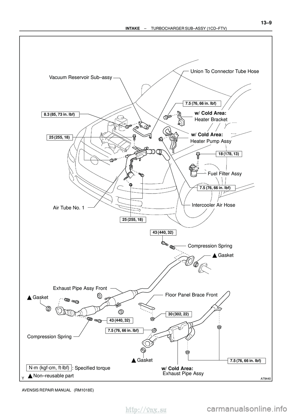
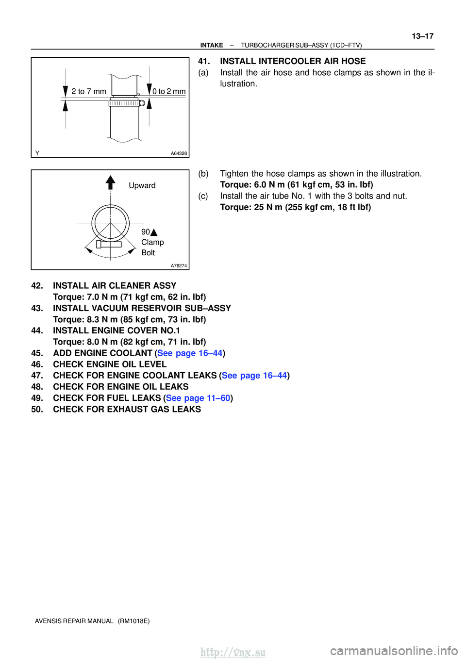
41.INSTALL INTERCOOLER AIR HOSE
(a)Install the air hose and hose clamps as shown in the il-
lustration.
(b)Tighten the hose clamps as shown in the illustration. Torque: 6.0 N �m (61 kgf�cm, 53 in. �lbf)
(c)Install the air tube No. 1 with the 3 bolts and nut. Torque: 25 N �m (255 kgf�cm, 18 ft�lbf)
42.INSTALL AIR CLEANER ASSY Torque: 7.0 N �m (71 kgf�cm, 62 in. �lbf)
43.INSTALL VACUUM RESERVOIR SUB±ASSY Torque: 8.3 N �m (85 kgf�cm, 73 in. �lbf)
44.INSTALL ENGINE COVER NO.1
Torque: 8.0 N �m (82 kgf�cm, 71 in. �lbf)
45.ADD ENGINE COOLANT(See page 16±44)
46. CHECK ENGINE OIL LEVEL
47.CHECK FOR ENGINE COOLANT LEAKS(See page 16±44)
48. CHECK FOR ENGINE OIL LEAKS
49.CHECK FOR FUEL LEAKS(See page 11±60)
50. CHECK FOR EXHAUST GAS LEAKS
http://vnx.su
Page 1792 of 2234
760WY±01
B67425
Claw
B67431
±
EXTERIOR/INTERIOR TRIM FRONT BUMPER
76±3
AVENSIS REPAIR MANUAL (RM1018E)
REPLACEMENT
HINT:
The installation is in the reverse order of the removal. However, when there is a special point concerning
the installation, it is indicated.
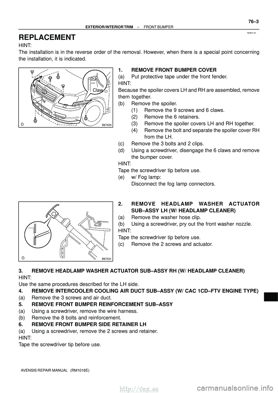
1. REMOVE FRONT BUMPER COVER
(a) Put protective tape under the front fender.
HINT:
Because the spoiler covers LH and RH are assembled, remove
them together.
(b) Remove the spoiler.(1) Remove the 9 screws and 6 claws.
(2) Remove the 6 retainers.
(3) Remove the spoiler covers LH and RH together.
(4) Remove the bolt and separate the spoiler cover RHfrom the LH.
(c) Remove the 3 bolts and 2 clips.
(d) Using a screwdriver, disengage the 6 claws and remove the bumper cover.
HINT:
Tape the screwdriver tip before use.
(e) w/ Fog lamp:
Disconnect the fog lamp connectors.
2. R E M O V E H E A D L A M P WA S H E R A C T U ATO R SUB±ASSY LH (W/ HEADLAMP CLEANER)
(a) Remove the washer hose clip.
(b) Using a screwdriver, pry out the front washer nozzle.
HINT:
Tape the screwdriver tip before use.
(c) Remove the 2 screws and actuator.
3. REMOVE HEADLAMP WASHER ACTUATOR SUB±ASSY RH (W/ HEADLAMP CLEANER)
HINT:
Use the same procedures described for the LH side.
4. REMOVE INTERCOOLER COOLING AIR DUCT SUB±ASSY (W/ CAC 1CD±FTV ENGI\
NE TYPE)
(a) Remove the 3 screws and air duct.
5. REMOVE FRONT BUMPER REINFORCEMENT SUB±ASSY
(a) Using a screwdriver, remove the wire harness.
(b) Remove the 8 bolts and reinforcement.
6. REMOVE FRONT BUMPER SIDE RETAINER LH
(a) Using a screwdriver, remove the 2 screws and retainer.
HINT:
Tape the screwdriver tip before use.
http://vnx.su