Page 1735 of 2234

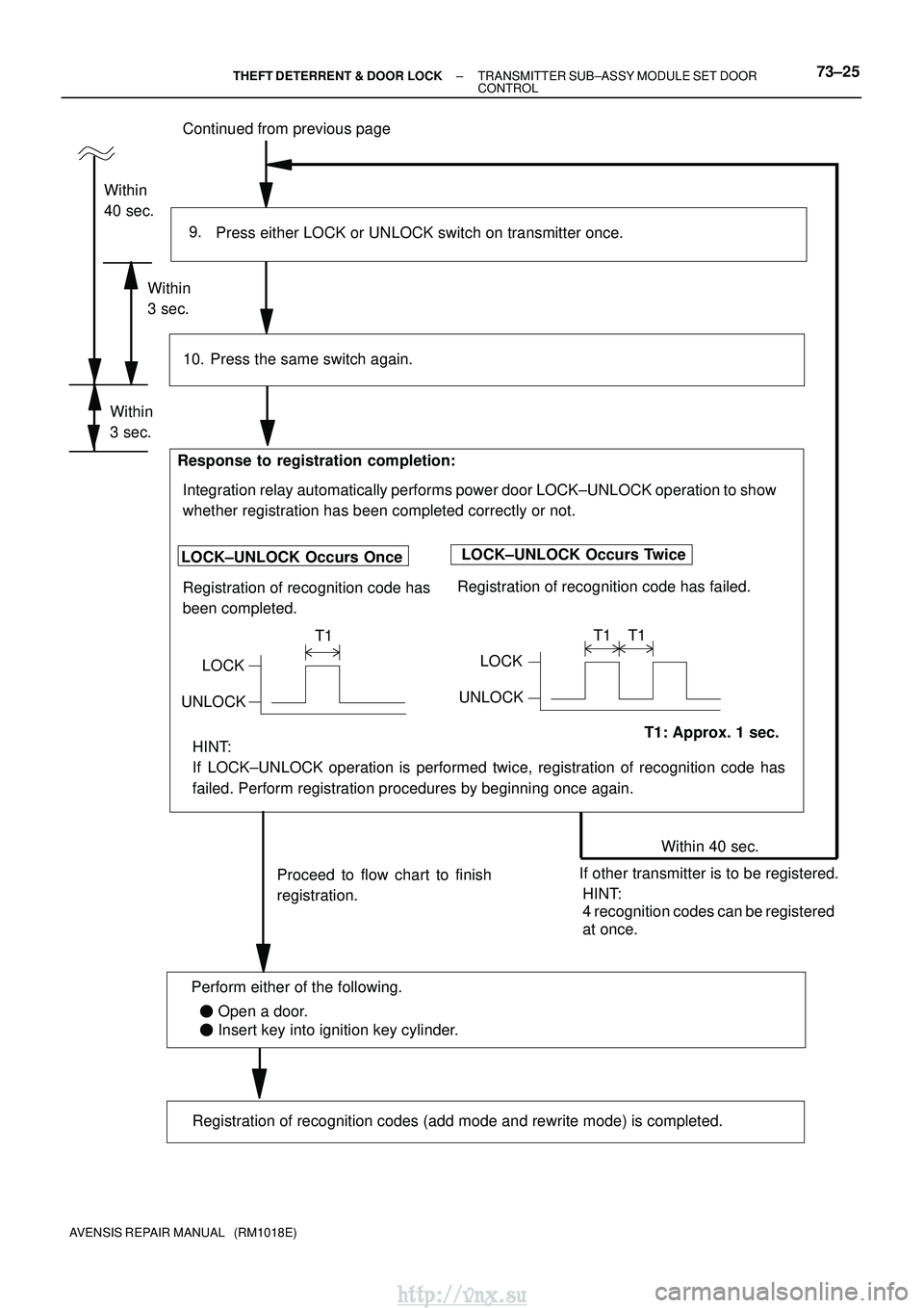
Continued from previous page
Press either LOCK or UNLOCK switch on transmitter once.
9.
Within 40 sec.
Proceed to flow chart to finish
registration.
Press the same switch again.
LOCK±UNLOCK Occurs Once Registration of recognition code has
been completed.
Response to registration completion:
T1: Approx. 1 sec.
LOCK±UNLOCK Occurs Twice
Registration of recognition code has failed.
10.
LOCK
UNLOCK
T1
LOCK
UNLOCK T1 T1
Within
40 sec.
If other transmitter is to be registered.
Within
3 sec.
Registration of recognition codes (add mode and rewrite mode) is compl\
eted.
Integration relay automatically performs power door LOCK±UNLOCK operation to show
whether registration has been completed correctly or not.
HINT:
4 recognition codes can be registered
at once.
HINT:
If LOCK±UNLOCK operation is performed twice, registration of recognition\
code has
failed. Perform registration procedures by beginning once again.
Within
3 sec.
�
Open a door.
� Insert key into ignition key cylinder.
Perform either of the following.
±
THEFT DETERRENT & DOOR LOCK TRANSMITTER SUB±ASSY MODULE SET DOOR
CONTROL73±25
AVENSIS REPAIR MANUAL (RM1018E)
http://vnx.su
Page 1737 of 2234

730EV±02
±
THEFT DETERRENT & DOOR LOCKWIRELESS DOOR LOCK CONTROL SYSTEM
73±15
AVENSIS REPAIR MANUAL (RM1018E)
ON±VEHICLE INSPECTION
1.CHECK WIRELESS DOOR LOCK CONTROL FUNCTIONS
HINT:
�The switch described in this text is a switch for transmitting signals (LO\
CK switch, UNLOCK switch and
luggage door (back door) unlock switch) which is built in the door control t\
ransmitter.
�All the functions listed below must be checked in comparison with the re\
mote control operational area.
(a)Put the vehicle under the conditions that allow the wireless control fun\
ction to be operated (See PRE-
CAUTION on page 73±14).
(b) Check the basic function. (1) Check whether the LED of the transmitter lights up 3 times when each switch i\
s pressed 3 times.
HINT:
If the LED does not light up when the switch has been pressed 3 times or more, it may have a dead bat\
tery.
(2) Check that all the doors including the luggage door (back door) lock when t\
he LOCK switch ispressed (However, this will not happen when any door is open).
(3) w/ Double locking system: Check that the double locking system is set when the LOCK switch is pressed within 5 seconds
after the above step (However, the double locking system is not applicable to the luggage door
(back door)).
CAUTION:
Never activate the double locking system when there are people in the vehicle, because all the doors
cannot be opened from inside the vehicle with the system on. If you lock\
the doors by accident, push
UNLOCK switch of the door control transmitter. (4) Check that all the doors including the luggage door (back door) unlock when\
the UNLOCK switchis pressed. Also, check that the double locking system is canceled at th\
e same time.
(5) Check that the luggage door (back door) unlocks when the luggage door (bac\
k door) unlock
switch is pressed.
HINT:
The UNLOCK switch and luggage door (back door) unlock switch can unlock t\
he doors even when any door
is open.
(c) Check the chattering prevention function. (1) Check that the corresponding operation occurs only once, and not repeated continuously whilethe switch is held down. However, when the switch is operated repeatedly at 1 second intervals,
check that the corresponding operation is carried out.
(d) Check the automatic locking function. (1) Check that all the doors including the luggage door (back door) lock automatically as long asnone of them have been opened or locked within approx. 30 seconds after they\
are unlocked
by pressing the switch.
(2) Check that the automatic locking function does not operate when any door incl\
uding the luggage
door (back door) has been opened or all of them have been locked within ap\
prox. 30 seconds
after they are unlocked by pressing the switch.
(e) Check the switch operation fail±safe function. (1) Check that the doors can not be locked by the switch while the key is in the \
ignition key cylinder.
However, this does not apply when the system is in the recognition code registra\
tion mode.
(f) Check the repeat function. (1) Check that all the doors attempt to automatically lock once again 1 second af\
ter the LOCK switchhas been pressed while the movement of the driver side door control knob, which is in the un-
locked state, is being restricted.
http://vnx.su
Page 1853 of 2234
![TOYOTA AVENSIS 2003 Service Repair Manual AVENSIS (EWD526E)5
B
[A]
: System Title
[B] : Indicates a Relay Block. No shading is used and
only the Relay Block No. is shown to distinguish it
from the J/B
Example: Indicates Relay Block No TOYOTA AVENSIS 2003 Service Repair Manual AVENSIS (EWD526E)5
B
[A]
: System Title
[B] : Indicates a Relay Block. No shading is used and
only the Relay Block No. is shown to distinguish it
from the J/B
Example: Indicates Relay Block No](/manual-img/14/57444/w960_57444-1852.png)
AVENSIS (EWD526E)5
B
[A]
: System Title
[B] : Indicates a Relay Block. No shading is used and
only the Relay Block No. is shown to distinguish it
from the J/B
Example: Indicates Relay Block No.1
[C] : ( ) is used to indicate different wiring and
connector, etc. when the vehicle model, engine
type, or specification is different.
[D] : Indicates related system.
[E] : Indicates the wiring harness and wiring harness
connector. The wiring harness with male terminal is
shown with arrows (
).
Outside numerals are pin numbers.
Female Male ( )
The first letter of the code for each wiring harness
and wiring harness connector(s) indicates the
component’s location, e.g, ”E” for the Engine
Compartment, ”I” for the Instrument Panel and
Surrounding area, and ”B” for the Body and
Surrounding area.
When more than one code has the first and second
letters in common, followed by numbers (e.g, IH1,
IH2), this indicates the same type of wiring harness
and wiring harness connector.
[F] : Represents a part (all parts are shown in sky blue).
The code is the same as the code used in parts
position.
[G] : Junction Block (The number in the circle is the J/B
No. and the connector code is shown beside it).
Junction Blocks are shaded to clearly separate
them from other parts.
3C indicates that
it is inside
Junction Block
No.3
Example:
[H] : Indicates the wiring color.
Wire colors are indicated by an alphabetical code.
B = Black W = White BR = Brown
L = Blue V = Violet SB = Sky Blue
R = Red G = Green LG = Light Green
P = Pink Y = Yellow GR = Gray
O = Orange
The first letter indicates the basic wire color and the
second letter indicates the color of the stripe.
Example: L – Y
L
(Blue) Y
(Yellow)
[I] : Indicates a wiring Splice Point (Codes are ”E” for the
Engine Room, ”I” for the Instrument Panel, and ”B”
for the Body).
The Location of splice Point I 5 is indicated by the
shaded section.
[J] : Indicates a shielded cable.
[K]: Indicates the pin number of the connector.
The numbering system is different for female and
male connectors.
Example: Numbered in order
from upper left to
lower right Numbered in order
from upper right to
lower left
Female Male
[L]: Indicates a ground point.
The first letter of the code for each ground point(s)
indicates the component’s location, e.g, ”E” for the
Engine Compartment, ”I” for the Instrument Panel
and Surrounding area, and ”B” for the Body and
Surrounding area.
[M] : Page No.
http://vnx.su