Page 1017 of 2234

21. INSTALL FRONT STABILIZER BRACKET NO.1 RH
(a) w/ HID: Install the front stabilizer bracket No.1 R")
F45155
A
B
F44620
26±28
±
FRONT SUSPENSION STABILIZER BAR FRONT
AVENSIS REPAIR MANUAL (RM1018E)
21. INSTALL FRONT STABILIZER BRACKET NO.1 RH
(a) w/ HID: Install the front stabilizer bracket No.1 RH and the height
control sensor (Front) with the 3 bolts.
Torque:
Bolt A: 5.4 N� m (55 kgf�cm, 48 in. �lbf)
Bolt B: 19 N� m (194 kgf�cm, 14 ft�lbf)
(b) w/o HID: Install the front stabilizer bracket No.1 RH with the 2 bolts.
Torque: 19 N� m (194 kgf�cm, 14 ft�lbf)
22.INSTALL FRONT SUSPENSION CROSSMEMBER SUB±ASSY (See page 26±16)
23.INSTALL FRONT SUSPENSION MEMBER BRACE REAR LH (See page 26±16)
24. INSTALL FRONT SUSPENSION MEMBER BRACE REAR RH
HINT:
Install the RH side by the same procedures as the LH side.
25. INSTALL RACK & PINION POWER STEERING GEAR ASSY
(a)Electric power steering model: See page 51±28
(b)Oil pressure power steering model: See page 51±36
26.INSTALL FRONT SUSPENSION ARM SUB±ASSY LOWER NO.1 LH (See page 30±6)
27. INSTALL FRONT SUSPENSION ARM SUB±ASSY LOWER NO.1 RH
HINT:
Connect the RH side by the same procedures as the LH side.
28.INSTALL TIE ROD END SUB±ASSY LH (See page 30±6)
29. INSTALL TIE ROD END SUB±ASSY RH
HINT:
Connect the RH side by the same procedures as the LH side.
30. INSTALL FRONT STABILIZER LINK ASSY LH
(a) Install the front stabilizer link assy LH with the 2 nuts.Torque: 74 N �m (755 kgf� cm, 55 ft�lbf)
HINT:
If the ball joint turns together with the nut, use a hexagon
wrench (6 mm) to hold the stud.
31. INSTALL FRONT STABILIZER LINK ASSY RH
HINT:
Install the RH side by the same procedures as the LH side.
32. INSTALL FRONT WHEEL Torque: 103 N� m (1,050 kgf�cm, 76 ft �lbf)
33.INSPECT AND ADJUST FRONT WHEEL ALIGNMENT (See page 26±6)
34.HEADLIGHT AIM ONLY (W/ DISCHARGE HEAD LAMP) (See page 65±19)
http://vnx.su
Page 1211 of 2234

42±1
AVENSIS REPAIR MANUAL (RM1018E)
CLUTCH SYSTEM (MTM)
PROBLEM SYMPTOMS TABLE
HINT:
Use the table below to help find the cause of the problem. The numbers")
4200B±04
±
CLUTCH CLUTCH SYSTEM (MTM)
42±1
AVENSIS REPAIR MANUAL (RM1018E)
CLUTCH SYSTEM (MTM)
PROBLEM SYMPTOMS TABLE
HINT:
Use the table below to help find the cause of the problem. The numbers indi\
cate the likelihood of the possible
cause in descending order. Check each part in the order shown. Replace these parts as necessary.
SymptomSuspect AreaSee page
Clutch grabs/chatters
1. Engine mounting (Loosen)
2. Clutch disc assy (Runout is excessive)
3. Clutch disc assy (Oily)
4. Clutch disc assy (Worn out)
5. Clutch disc torsion rubber (Damaged)
6. Clutch disc assy (Glazed)
7. Diaphragm spring (Out of tip alignment)±
42±26
42±26
42±26
42±26
42±26
42±26
Clutch pedal spongy
1. Clutch Line (Air in line)
2. Master cylinder (Damaged)
3. Release cylinder rubber (Damaged)±
42±13
42±17
Clutch noisy1. Clutch release bearing assy (Worn, dirty, or damaged)
2. Clutch disc torsion rubber (Damaged)42±26
42±26
Clutch slips
1. Clutch pedal (Free play out of adjustment)
2. Clutch disc assy (Oily)
3. Clutch disc assy (Worn out)
4. Diaphragm spring (Damaged)
5. Pressure plate (Distortion)
6. Flywheel sub±assy (Distortion)42±2
42±26
42±26
42±26
42±26 ±
Clutch does not disengage
1. Clutch pedal (Free play out of adjustment)
2. Clutch line (Air in line)
3. Master cylinder (Damaged)
4. Release cylinder cup (Damaged)
5. Clutch disc assy (Out of true)
6. Clutch disc assy (Runout of excessive)
7. Clutch disc assy (Lining broken)
8. Clutch disc assy (Dirty or burned)
9. Clutch disc assy (Oily)
10.Clutch disc assy (Lack of spline grease)42±2
±
42±13
42±17
42±26
42±26
42±26
42±26
42±26
42±26
http://vnx.su
Page 1238 of 2234

PROBLEM SYMPTOMS TABLE
HINT:
Use the table below to help you find the cause of the problem. The numbers \
indicate")
5000D±14
50±2
±
STEERING COLUMN STEERING SYSTEM
AVENSIS REPAIR MANUAL (RM1018E)
PROBLEM SYMPTOMS TABLE
HINT:
Use the table below to help you find the cause of the problem. The numbers \
indicate the likelihood of the
cause in the descending order. Check each part in the order shown. Repair or replace these parts as n\
eces-
sary.
Oil pressure power steering:
SymptomSuspect AreaSee page
Hard steering
11. Tires (Improperly inflated)
12.Power steering fluid level (Low)
13.Drive belt (Loose)
14.Front wheel alignment (Incorrect)
15.Steering system joints (Worn)
16.Suspension arm ball joints (Worn)
17.Steering column (Binding)
18.Power steering vane pump
19.Power steering gear28±1
51±4
51±4
26±6 ±
26±24 ±
51±9
51±19
51±36
Poor return
1. Tires (Improperly inflated)
2. Front wheel alignment (Incorrect)
3. Steering column (Binding)
4. Power steering gear28±1
26±6 ±
51±36
Excessive play
1. Steering system joints (Worn)
2. Suspension arm ball joints (Worn)
3. Intermediate shaft, Sliding yoke (Worn)
4. Front wheel bearing (Worn)
5. Power steering gear±
26±24 ±
30±22
51±36
Abnormal noise
1. Power steering fluid level (Low)
2. Steering system joints (Worn)
3. Power steering vane pump
4. Power steering gear51±4 ±
51±9
51±19
51±36
http://vnx.su
Page 1267 of 2234
5106Z±04
D30360
�
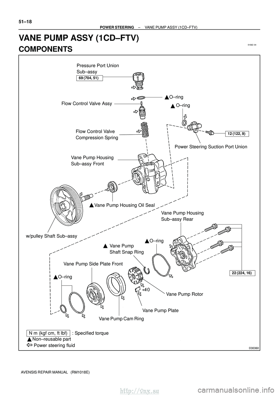
12 (122, 9)Flow Control Valve
Compression SpringPower Steering Suction Port Union
Vane Pump Housing Oil Seal
�
Vane Pump
Shaft Snap Ring
Vane Pump Side Plate Front
Vane Pump Rotor
Vane Pump Plate
Vane Pump Cam Ring
N �m (kgf� cm, ft�lbf) : Specified torque
� Non±reusable part
Power steering fluid
�
�
�
22 (224, 16)
� 10
Pressure Port Union
Sub±assy
Flow Control Valve Assy
Vane Pump Housing
Sub±assy Front
�
Vane Pump Housing
Sub±assy Rear
69 (704, 51)
O±ringO±ring
O±ring
O±ring
w/pulley Shaft Sub±assy
51±18
±
POWER STEERING VANE PUMP ASSY (1CD±FTV)
AVENSIS REPAIR MANUAL (RM1018E)
VANE PUMP ASSY (1CD±FTV)
COMPONENTS
http://vnx.su
Page 1272 of 2234
Oil Seal
������D30334
Vinyl Tape
±
POWER STEERING VANE PUMP ASSY (1CD±FTV)
51±23
AVENSIS REPAIR MANUAL (RM1018E)
If necessary, replace t")
D31004
Inscribed Mark
R08702
Vernier Calipers
F42121
SST(s)Oil Seal
������D30334
Vinyl Tape
±
POWER STEERING VANE PUMP ASSY (1CD±FTV)
51±23
AVENSIS REPAIR MANUAL (RM1018E)
If necessary, replace the flow control valve assy with the one
having the same letter as inscribed on the housing sub±assy
front
Inscribed mark: A, B, C, D, E or F
HINT:
There are 6 different marks for flow control valve assy.
MarkPart number
A44330±05190
B44330±05200
C44330±05210
D44330±05220
E44330±05230
F44330±05240
18. INSPECT FLOW CONTROL VALVE COMPRESSION SPRING
(a) Using vernier calipers, measure the free length of the compression spring.
Minimum free length: 36.9 mm ( 1.453 in.)
If it is less than the minimum, replace the compression spring.
19. INSPECT PRESSURE PORT UNION SUB±ASSY
(a) If the union seat in the pressure port union sub±assy is remarkably damaged, it may cause flui\
d leak- age. Replace the pressure port union sub±assy.
20. INSTALL VANE PUMP HOUSING OIL SEAL
(a) Coat a new housing oil seal lip with power steering fluid.
(b) Using SST(s) and a press, install a new housing oil seal.SST 09950±60010 (09951±00280), 09950±70010
(09951±07100)
NOTICE:
Make sure that the oil seal is installed facing in the correct
direction.
21. INSTALL W/PULLEY SHAFT SUB±ASSY
(a) Coat inside bushing surface of the housing sub±assy front with power steering fluid.
(b) Gradually insert the w/pulley shaft sub±assy.
NOTICE:
Do not damage the oil seal lip.
HINT:
Tape the shaft before inserting.
http://vnx.su
Page 1275 of 2234

51±26
±
POWER STEERING VANE PUMP ASSY (1CD±FTV)
AVENSIS REPAIR MANUAL (RM1018E)
28. INSTALL FLOW CONTROL VALVE ASSY
(a) Coat the compressi")
������D30361
D30580
B
B
B
A
D30581
Fulcrum
Length
SST(s)
51±26
±
POWER STEERING VANE PUMP ASSY (1CD±FTV)
AVENSIS REPAIR MANUAL (RM1018E)
28. INSTALL FLOW CONTROL VALVE ASSY
(a) Coat the compression spring and the flow control valve assy with power steering fluid.
(b) Install the compression spring and the flow control valve assy.
(c) Coat a new O±ring with power steering fluid and install it onto the pressure port union sub±assy.
(d) Install the pressure port union sub±assy. Torque: 69 N �m (704 kgf� cm, 51 ft�lbf)
29. INSTALL POWER STEERING SUCTION PORT UNION
(a) Coat a new O±ring with power steering fluid, and install it to the su\
ction port union.
(b) Install the suction port union with the bolt. Torque: 12 N �m (122 kgf� cm, 9 ft�lbf)
30. INSTALL VANE PUMP ASSY
(a) Install the vane pump assy and vane pump bracket rear with the 4 bolts.
Torque:
Bolt A: 72 N� m (734 kgf�cm, 53 ft�lbf)
Bolt B: 39 N� m (398 kgf�cm, 29 ft�lbf)
31. CONNECT PRESSURE FEED TUBE ASSY
(a) Using SST(s), connect the pressure feed tube assy. SST 09023±12700
Torque: 41 N �m (414 kgf� cm, 30 ft�lbf)
HINT:
�Use a torque wrench with a fulcrum length of 345 mm
(13.58 in.).
�This torque value is effective when SST(s) is parallel to a
torque wrench.
(b) Install the tube clamp with the bolt. Torque: 8.0 N �m (82 kgf �cm, 71 in. �lbf)
32. CONNECT OIL RESERVOIR TO PUMP HOSE NO.1
(a) Connect the oil reservoir to pump hose No. 1 with the clip.
NOTICE:
Take care not to spill fluid on the V belt.
33. INSTALL V (COOLER COMPRESSOR TO CRANKSHAFT PULLEY) BELT NO.1 (See page 55±46)
34. ADJUST V (COOLER COMPRESSOR TO CRANKSHAFT PULLEY) BELT NO.1
(See page 55±46)
35.ADD POWER STEERING FLUID (See page 51±4)
36.BLEED POWER STEERING FLUID (See page 51±4)
37.CHECK POWER STEERING FULUID LEVEL IN RESERVER (See page 51±4)
38. INSPECT FLUID LEAK
http://vnx.su
Page 1276 of 2234
510DF±02
F42473
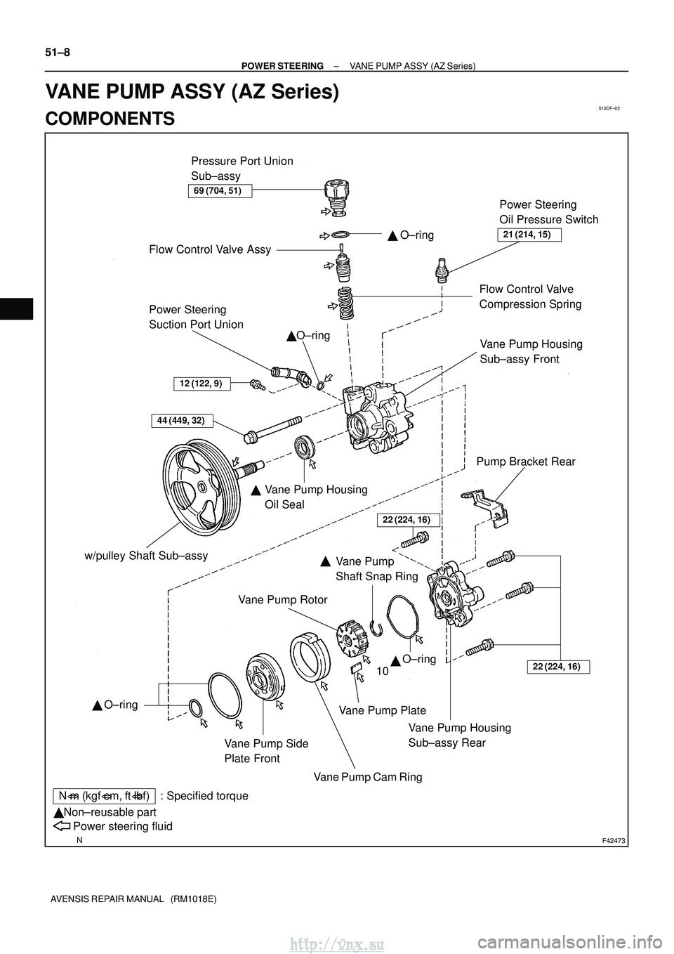
Power Steering
Suction Port UnionO±ring
�
w/pulley Shaft Sub±assy Vane Pump Side
Plate FrontVane Pump Cam Ring�
10
�
N�m (kgf� cm, ft�lbf) : Specified torque
Non±reusable part
�
Power steering fluid
Pump Bracket Rear
Flow Control Valve Assy
�
Flow Control Valve
Compression Spring
44 (449, 32)
Vane Pump Housing
Sub±assy Rear Vane Pump Housing
Sub±assy Front
�
Vane Pump Rotor
Vane Pump Plate
22 (224, 16)
Vane Pump Housing
Oil Seal
�
Power Steering
Oil Pressure Switch
21 (214, 15)
69 (704, 51)
Vane Pump
Shaft Snap Ring
� O±ring
O±ring
O±ring
22 (224, 16)
Pressure Port Union
Sub±assy
12 (122, 9)
51±8
±
POWER STEERING VANE PUMP ASSY (AZ Series)
AVENSIS REPAIR MANUAL (RM1018E)
VANE PUMP ASSY (AZ Series)
COMPONENTS
http://vnx.su
Page 1278 of 2234

AVENSIS REPAIR MANUAL (RM1018E)
9. REMOVE POWER STEERING SUCTION PORT UNION
(a) Remove the bolt and the suction port union.
(")
F42475
C84483
C57767
51±10
±
POWER STEERING VANE PUMP ASSY (AZ Series)
AVENSIS REPAIR MANUAL (RM1018E)
9. REMOVE POWER STEERING SUCTION PORT UNION
(a) Remove the bolt and the suction port union.
(b) Remove the O±ring from the suction port union. 10. REMOVE FLOW CONTROL VALVE ASSY
(a) Remove the pressure port union sub±assy.
(b) Remove the O±ring from the pressure port union sub±assy.
(c) Remove the flow control valve assy and the compression spring.
11. REMOVE POWER STEERING OIL PRESSURE SWITCH
NOTICE:
If the oil pressure switch is dropped or damaged, replace it with a new \
one. 12. REMOVE VANE PUMP HOUSING SUB±ASSY REAR
(a) Remove the 4 bolts and housing sub±assy rear from thehousing sub±assy front.
(b) Remove the O±ring from the housing sub±assy rear.
13. REMOVE W/PULLEY SHAFT SUB±ASSY
(a) Using 2 screwdrivers, remove the snap ring from the w/ pulley shaft sub±assy.
(b) Remove the w/pulley shaft sub±assy.
14. REMOVE VANE PUMP ROTOR
(a) Remove the 10 vane pump plates.
(b) Remove the vane pump rotor.
15. REMOVE VANE PUMP CAM RING
http://vnx.su