Page 912 of 2234
17045±03
A56466
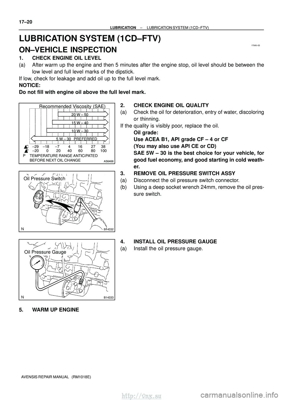
Recommended Viscosity (SAE)
BEFORE NEXT OIL CHANGE TEMPERATURE RANGE ANTICiPATED416 2738
0 20 40 60 80 100
±29
±20 ±18 ±7
� C
� F 20 W ± 50
15 W ± 40
10 W ± 30
5 W ± 30 PREFERRED
B14332
Oil Pressure Switch
B14333
Oil Pressure Gauge
17±20
±
LUBRICATION LUBRICATION SYSTEM (1CD±FTV)
AVENSIS REPAIR MANUAL (RM1018E)
LUBRICATION SYSTEM (1CD±FTV)
ON±VEHICLE INSPECTION
1. CHECK ENGINE OIL LEVEL
(a) After warm up the engine and then 5 minutes after the engine stop, oil l\
evel should be between the low level and full level marks of the dipstick.
If low, check for leakage and add oil up to the full level mark.
NOTICE:
Do not fill with engine oil above the full level mark.
2. CHECK ENGINE OIL QUALITY
(a) Check the oil for deterioration, entry of water, discoloringor thinning.
If the quality is visibly poor, replace the oil. Oil grade:
Use ACEA B1, API grade CF ± 4 or CF
(You may also use API CE or CD)
SAE 5W ± 30 is the best choice for your vehicle, for
good fuel economy, and good starting in cold weath-
er.
3. REMOVE OIL PRESSURE SWITCH ASSY
(a) Disconnect the oil pressure switch connector.
(b) Using a deep socket wrench 24mm, remove the oil pres- sure switch.
4. INSTALL OIL PRESSURE GAUGE
(a) Install the oil pressure gauge.
5. WARM UP ENGINE
http://vnx.su
Page 914 of 2234
1700F±10
A56466
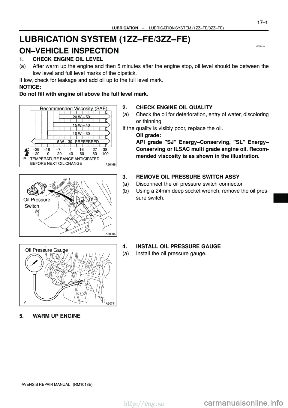
Recommended Viscosity (SAE)
BEFORE NEXT OIL CHANGE TEMPERATURE RANGE ANTICiPATED416 2738
0 20 40 60 80 100
±29
±20 ±18 ±7
� C
� F 20 W ± 50
15 W ± 40
10 W ± 30
5 W ± 30 PREFERRED
Oil Pressure
Switch
A80004
Oil Pressure GaugeOil Pressure Gauge
A50711
±
LUBRICATION LUBRICATION SYSTEM (1ZZ±FE/3ZZ±FE)
17±1
AVENSIS REPAIR MANUAL (RM1018E)
LUBRICATION SYSTEM (1ZZ±FE/3ZZ±FE)
ON±VEHICLE INSPECTION
1. CHECK ENGINE OIL LEVEL
(a) After warm up the engine and then 5 minutes after the engine stop, oil l\
evel should be between the
low level and full level marks of the dipstick.
If low, check for leakage and add oil up to the full level mark.
NOTICE:
Do not fill with engine oil above the full level mark.
2. CHECK ENGINE OIL QUALITY
(a) Check the oil for deterioration, entry of water, discoloringor thinning.
If the quality is visibly poor, replace the oil. Oil grade:
API grade ºSJº Energy±Conserving, ºSLº Energy±
Conserving or ILSAC multi grade engine oil. Recom-
mended viscosity is as shown in the illustration.
3. REMOVE OIL PRESSURE SWITCH ASSY
(a) Disconnect the oil pressure switch connector.
(b) Using a 24mm deep socket wrench, remove the oil pres- sure switch.
4. INSTALL OIL PRESSURE GAUGE
(a) Install the oil pressure gauge.
5. WARM UP ENGINE
http://vnx.su
Page 947 of 2234
B01301
IG0316
B02101
1.1 mm
B62019
18±10
±
IGNITION IGNITION SYSTEM (1AZ±FE)
AVENSIS REPAIR MANUAL (RM1018E)
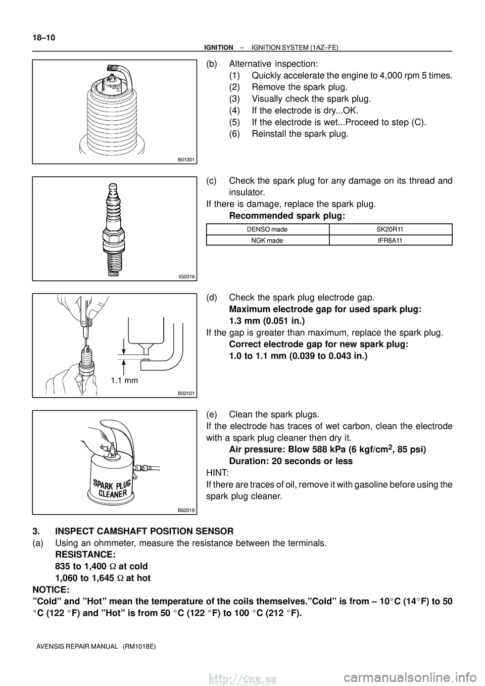
(b) Alternative inspection: (1) Quickly accelerate the engine to 4,000 rpm 5 times.
(2) Remove the spark plug.
(3) Visually check the spark plug.
(4) If the electrode is dry...OK.
(5) If the electrode is wet...Proceed to step (C).
(6) Reinstall the spark plug.
(c) Check the spark plug for any damage on its thread and insulator.
If there is damage, replace the spark plug. Recommended spark plug:
DENSO madeSK20R11
NGK madeIFR6A11
(d) Check the spark plug electrode gap.Maximum electrode gap for used spark plug:
1.3 mm (0.051 in.)
If the gap is greater than maximum, replace the spark plug. Correct electrode gap for new spark plug:
1.0 to 1.1 mm (0.039 to 0.043 in.)
(e) Clean the spark plugs.
If the electrode has traces of wet carbon, clean the electrode
with a spark plug cleaner then dry it. Air pressure: Blow 588 kPa (6 kgf/cm
2, 85 psi)
Duration: 20 seconds or less
HINT:
If there are traces of oil, remove it with gasoline before using the
spark plug cleaner.
3. INSPECT CAMSHAFT POSITION SENSOR
(a) Using an ohmmeter, measure the resistance between the terminals. RESISTANCE:
835 to 1,400 � at cold
1,060 to 1,645 �at hot
NOTICE:
ºColdº and ºHotº mean the temperature of the coils themselve\
s.ºColdº is from ± 10 �C (14� F) to 50
� C (122 �F) and ºHotº is from 50 � C (122 �F) to 100 � C (212 �F).
http://vnx.su
Page 952 of 2234
A78640
1.0 to 1.1 mm
B62019
±
IGNITION IGNITION SYSTEM (1AZ±FSE)
18±15
AVENSIS REPAIR MANUAL (RM1018E)
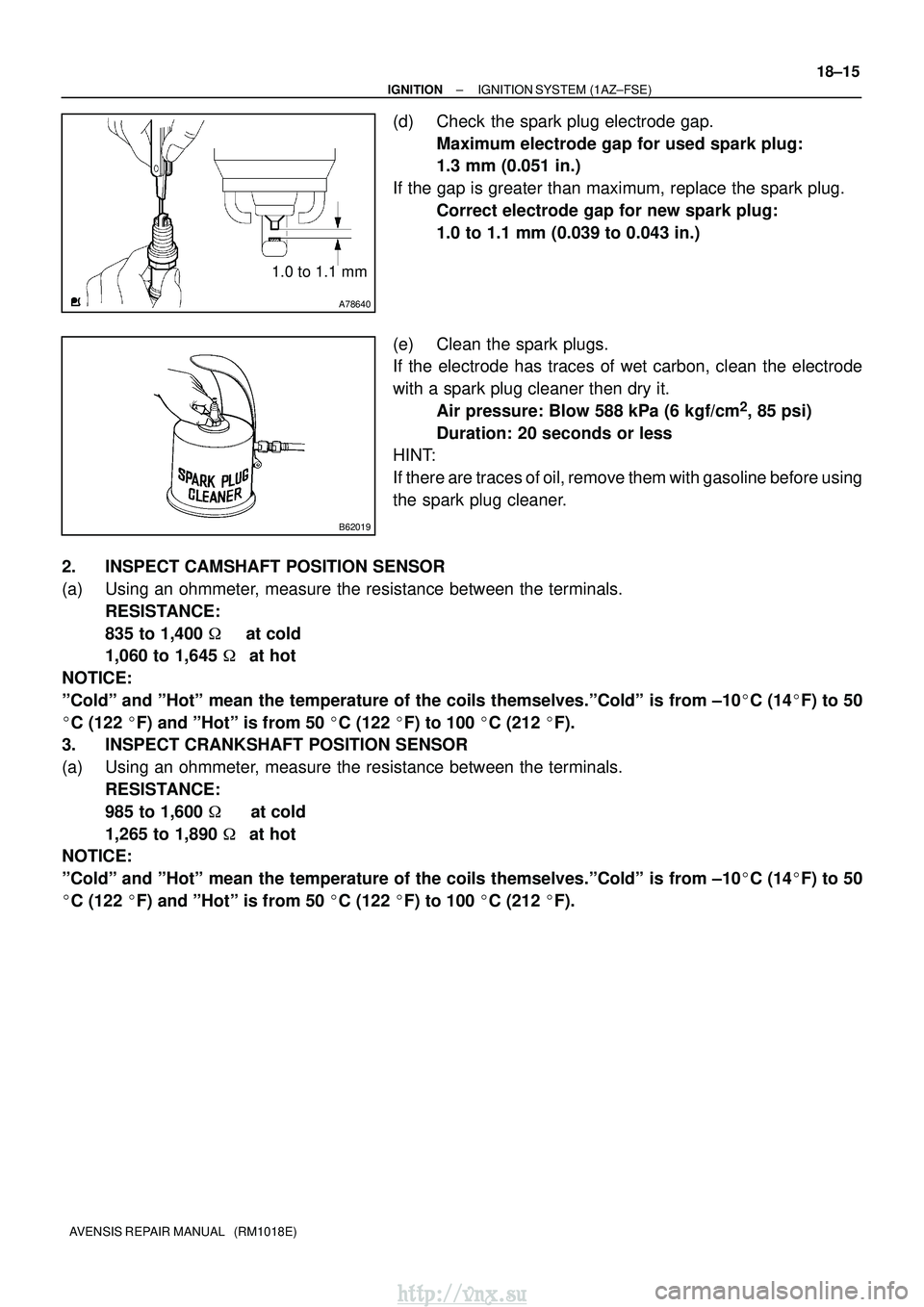
(d) Check the spark plug electrode gap.
Maximum electrode gap for used spark plug:
1.3 mm (0.051 in.)
If the gap is greater than maximum, replace the spark plug. Correct electrode gap for new spark plug:
1.0 to 1.1 mm (0.039 to 0.043 in.)
(e) Clean the spark plugs.
If the electrode has traces of wet carbon, clean the electrode
with a spark plug cleaner then dry it. Air pressure: Blow 588 kPa (6 kgf/cm
2, 85 psi)
Duration: 20 seconds or less
HINT:
If there are traces of oil, remove them with gasoline before using
the spark plug cleaner.
2. INSPECT CAMSHAFT POSITION SENSOR
(a) Using an ohmmeter, measure the resistance between the terminals. RESISTANCE:
835 to 1,400 � at cold
1,060 to 1,645 �at hot
NOTICE:
ºColdº and ºHotº mean the temperature of the coils themselves.ºColdº is\
from ±10 �C (14� F) to 50
� C (122 �F) and ºHotº is from 50 � C (122 �F) to 100 � C (212 �F).
3. INSPECT CRANKSHAFT POSITION SENSOR
(a) Using an ohmmeter, measure the resistance between the terminals.
RESISTANCE:
985 to 1,600 � at cold
1,265 to 1,890 �at hot
NOTICE:
ºColdº and ºHotº mean the temperature of the coils themselves.ºColdº is\
from ±10 �C (14� F) to 50
� C (122 �F) and ºHotº is from 50 � C (122 �F) to 100 � C (212 �F).
http://vnx.su
Page 955 of 2234
1807P±01
A50033
P03783
P03792
±
IGNITION IGNITION SYSTEM (1ZZ±FE/3ZZ±FE)
18±3
AVENSIS REPAIR MANUAL (RM1018E)
INSPECTION
1. INSPECT SPARK PLUG
(a) Clean the spark plugs.
If the electrode has traces of wet carbon, clean the electrode
with a spark plug cleaner then dry it.
Air pressure: Below 588 kPa (6kg/cm
2, 85 psi)
Duration: 20 seconds or less
(b) Check the spark plug for any damage on its thread and insulator damage.
If there is damage, replace the spark plug. Recommended spark plug:
DENSO madeK16R±U11
NGK madeBKR5EYA11
(c) Adjust electrode gap.Electrode gap: 1.0 to 1.1 mm (0.039 to 0.043 in.)
2. INSPECT CAMSHAFT POSITION SENSOR
(a) Using an ohmmeter, measure the resistance between the terminals. RESISTANCE:
835 to 1,400 � at cold
1,060 to 1,645 �at hot
NOTICE:
ºColdº and ºHotº mean the temperature of the coils themselve\
s.ºColdº is from ± 10 �C (14� F) to 50
� C (122 �F) and ºHotº is from 50 � C (122 �F) to 100 � C (212 �F).
http://vnx.su
Page 1000 of 2234
260DQ±01
F13686
C80293
26±16±
FRONT SUSPENSION FRONT SUSPENSION ARM SUB±ASSY LOWER NO.1
LH (ATM)
AVENSIS REPAIR MANUAL (RM1018E)
FRONT SUSPENSION ARM SUB±ASSY LOWER NO.1
LH (ATM)
REPLACEMENT
HINT:
�COMPONENTS: See page 26±2
�Replace the RH side (Engine: 1AZ) by the same procedures as the LH (A\
TM) side.
�Replace the RH side (Engine: 1ZZ) by the same procedures as the LH (M\
TM) side.
1. REMOVE FRONT WHEELS
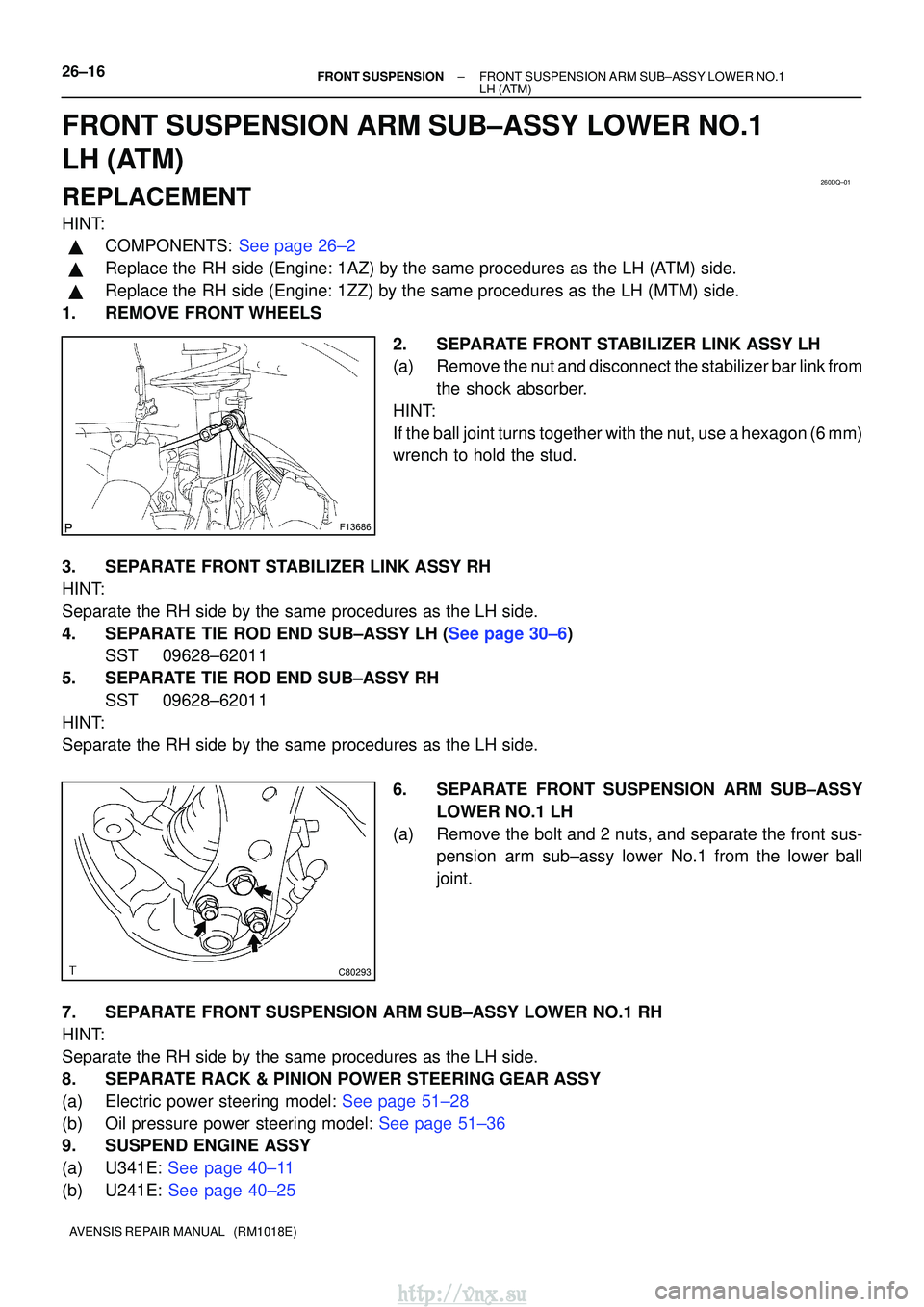
2. SEPARATE FRONT STABILIZER LINK ASSY LH
(a) Remove the nut and disconnect the stabilizer bar link fromthe shock absorber.
HINT:
If the ball joint turns together with the nut, use a hexagon (6 mm)
wrench to hold the stud.
3. SEPARATE FRONT STABILIZER LINK ASSY RH
HINT:
Separate the RH side by the same procedures as the LH side.
4.SEPARATE TIE ROD END SUB±ASSY LH (See page 30±6) SST 09628±62011
5. SEPARATE TIE ROD END SUB±ASSY RH SST 09628±62011
HINT:
Separate the RH side by the same procedures as the LH side.
6. SEPARATE FRONT SUSPENSION ARM SUB±ASSYLOWER NO.1 LH
(a) Remove the bolt and 2 nuts, and separate the front sus- pension arm sub±assy lower No.1 from the lower ball
joint.
7. SEPARATE FRONT SUSPENSION ARM SUB±ASSY LOWER NO.1 RH
HINT:
Separate the RH side by the same procedures as the LH side.
8. SEPARATE RACK & PINION POWER STEERING GEAR ASSY
(a)Electric power steering model: See page 51±28
(b)Oil pressure power steering model: See page 51±36
9. SUSPEND ENGINE ASSY
(a)U341E: See page 40±11
(b)U241E: See page 40±25
http://vnx.su
Page 1002 of 2234
C95318
C87504
C86742
AA
AAB
B
C95317
AA
A
B
26±18
±
FRONT SUSPENSIONFRONT SUSPENSION ARM SUB±ASSY LOWER NO.1
LH(ATM)
AVENSIS REPAIR MANUAL (RM1018E)
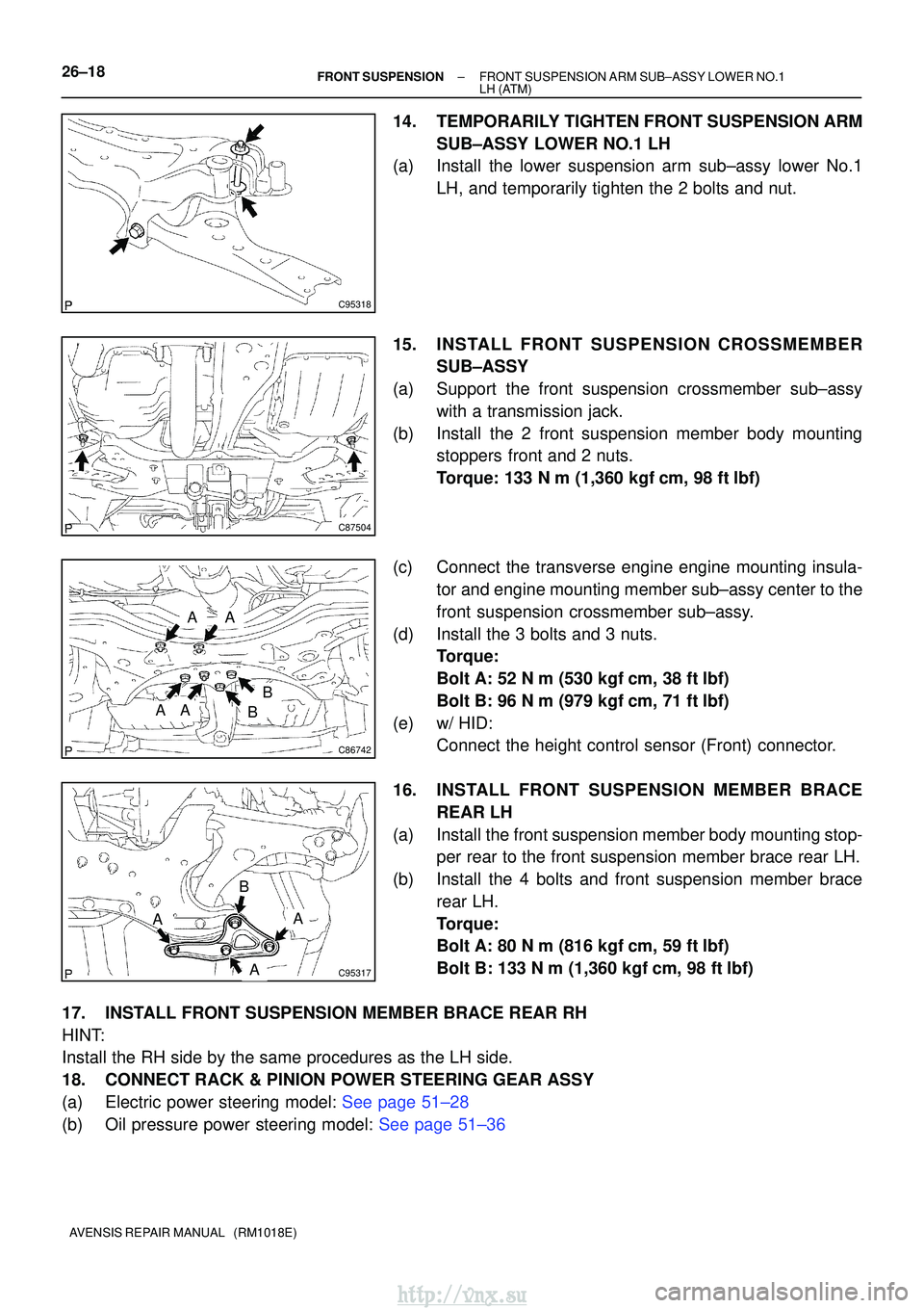
14.TEMPORARILY TIGHTEN FRONT SUSPENSION ARM SUB±ASSY LOWER NO.1 LH
(a)Install the lower suspension arm sub±assy lower No.1
LH, and temporarily tighten the 2 bolts and nut.
15.INSTALL FRONT SUSPENSION CROSSMEMBER SUB±ASSY
(a)Support the front suspension crossmember sub±assy with a transmission jack.
(b)Install the 2 front suspension member body mounting stoppers front and 2 nuts.
Torque: 133 N�m (1,360 kgf�cm, 98 ft�lbf)
(c)Connect the transverse engine engine mounting insula- tor and engine mounting member sub±assy center to the
front suspension crossmember sub±assy.
(d)Install the 3 bolts and 3 nuts. Torque:
Bolt A: 52 N�m (530 kgf�cm, 38 ft�lbf)
Bolt B: 96 N�m (979 kgf�cm, 71 ft�lbf)
(e)w/ HID: Connect the height control sensor (Front) connector.
16.INSTALL FRONT SUSPENSION ME MBER BRACE
REAR LH
(a)Install the front suspension member body mounting stop- per rear to the front suspension member brace rear LH.
(b)Install the 4 bolts and front suspension member brace rear LH.
Torque:
Bolt A: 80 N�m (816 kgf�cm, 59 ft�lbf)
Bolt B: 133 N�m (1,360 kgf �cm, 98 ft�lbf)
17.INSTALL FRONT SUSPENSION MEMBER BRACE REAR RH
HINT:
Install the RH side by the same procedures as the LH side.
18.CONNECT RACK & PINION POWER STEERING GEAR ASSY
(a)Electric power steering model: See page 51±28
(b)Oil pressure power steering model: See page 51±36
http://vnx.su
Page 1015 of 2234
2600P±03
F44620
G21679
26±26
±
FRONT SUSPENSION STABILIZER BAR FRONT
AVENSIS REPAIR MANUAL (RM1018E)
STABILIZER BAR FRONT
REPLACEMENT
HINT:
COMPONENTS: See page 26±2
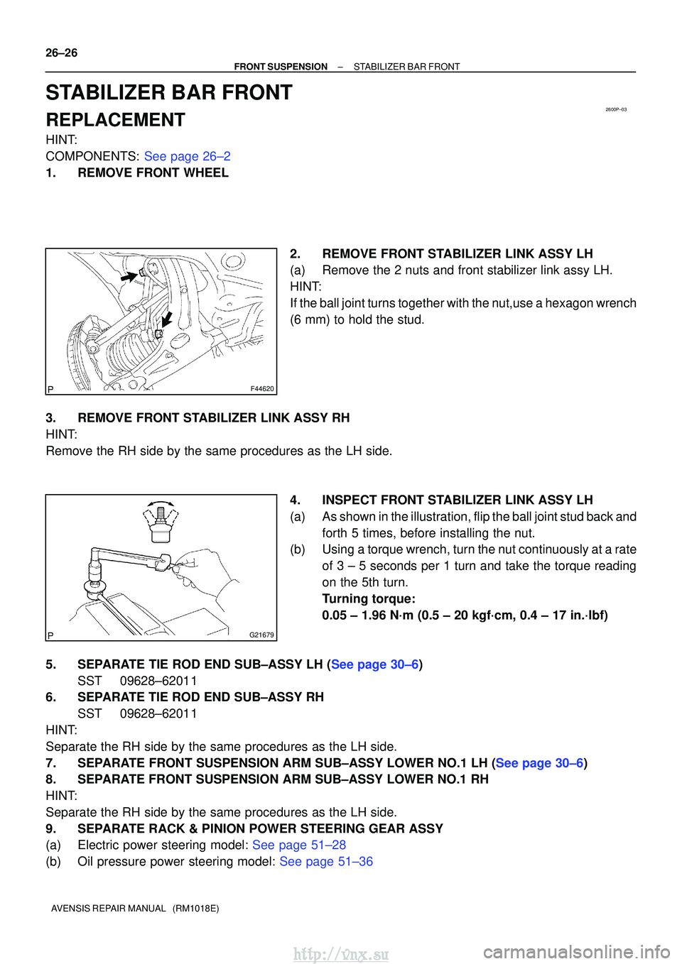
1. REMOVE FRONT WHEEL 2. REMOVE FRONT STABILIZER LINK ASSY LH
(a) Remove the 2 nuts and front stabilizer link assy LH.
HINT:
If the ball joint turns together with the nut,use a hexagon wrench
(6 mm) to hold the stud.
3. REMOVE FRONT STABILIZER LINK ASSY RH
HINT:
Remove the RH side by the same procedures as the LH side. 4. INSPECT FRONT STABILIZER LINK ASSY LH
(a) As shown in the illustration, flip the ball joint stud back andforth 5 times, before installing the nut.
(b) Using a torque wrench, turn the nut continuously at a rate
of 3 ± 5 seconds per 1 turn and take the torque reading
on the 5th turn.
Turning torque:
0.05 ± 1.96 N´m (0.5 ± 20 kgf´cm, 0.4 ± 17 in.´lbf)
5.SEPARATE TIE ROD END SUB±ASSY LH (See page 30±6) SST 09628±62011
6. SEPARATE TIE ROD END SUB±ASSY RH
SST 09628±62011
HINT:
Separate the RH side by the same procedures as the LH side.
7.SEPARATE FRONT SUSPENSION ARM SUB±ASSY LOWER NO.1 LH (See page 30±6)
8. SEPARATE FRONT SUSPENSION ARM SUB±ASSY LOWER NO.1 RH
HINT:
Separate the RH side by the same procedures as the LH side.
9. SEPARATE RACK & PINION POWER STEERING GEAR ASSY
(a)Electric power steering model: See page 51±28
(b)Oil pressure power steering model: See page 51±36
http://vnx.su