Page 705 of 2234
A09609
A09680
SST
A09611
A09606
A09609
±
ENGINE MECHANICAL TIMING BELT (1CD±FTV)
14±309
AVENSIS REPAIR MANUAL (RM1018E)
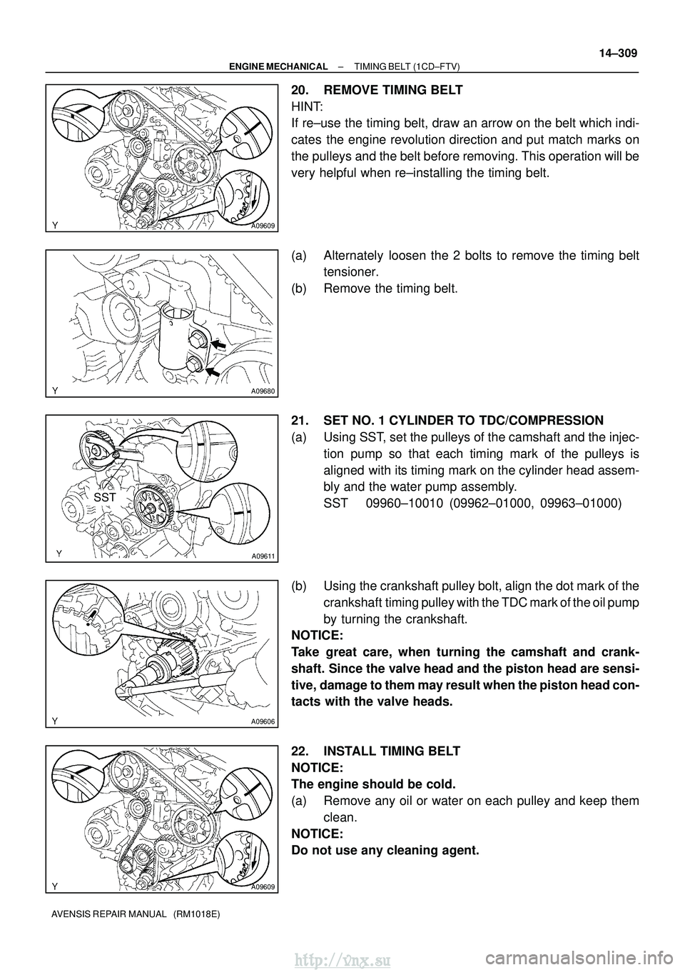
20. REMOVE TIMING BELT
HINT:
If re±use the timing belt, draw an arrow on the belt which indi-
cates the engine revolution direction and put match marks on
the pulleys and the belt before removing. This operation will be
very helpful when re±installing the timing belt.
(a) Alternately loosen the 2 bolts to remove the timing belt
tensioner.
(b) Remove the timing belt.
21. SET NO. 1 CYLINDER TO TDC/COMPRESSION
(a) Using SST, set the pulleys of the camshaft and the injec- tion pump so that each timing mark of the pulleys is
aligned with its timing mark on the cylinder head assem-
bly and the water pump assembly.
SST 09960±10010 (09962±01000, 09963±01000)
(b) Using the crankshaft pulley bolt, align the dot mark of the crankshaft timing pulley with the TDC mark of the oil pump
by turning the crankshaft.
NOTICE:
Take great care, when turning the camshaft and crank-
shaft. Since the valve head and the piston head are sensi-
tive, damage to them may result when the piston head con-
tacts with the valve heads.
22. INSTALL TIMING BELT
NOTICE:
The engine should be cold.
(a) Remove any oil or water on each pulley and keep them
clean.
NOTICE:
Do not use any cleaning agent.
http://vnx.su
Page 716 of 2234
141B6±01
A77281
A77378
No. 1 Cylinder TDC/Compression
IN
EX
A77379
No. 4 Cylinder TDC/Compression
IN
EX
14±106
±
ENGINE MECHANICALVALVE CLEARANCE(1AZ±FE)
AVENSIS REPAIR MANUAL (RM1018E)
VALVE CLEARANCE(1AZ±FE)
ADJUSTMENT
1.REMOVE RADIATOR SUPPORT OPENING COVER
2.REMOVE ENGINE ROOM COVER SIDE
3.REMOVE ENGINE UNDER COVER RH 4.REMOVE ENGINE COVER SUB±ASSY NO.1
(a)Remove 2 nuts and the engine cover No. 1.
5.REMOVE IGNITION COIL ASSY
(a)Remove 4 bolts and the ignition coils.
6.REMOVE CYLINDER HEAD COVER SUB±ASSY (See page 14±171)
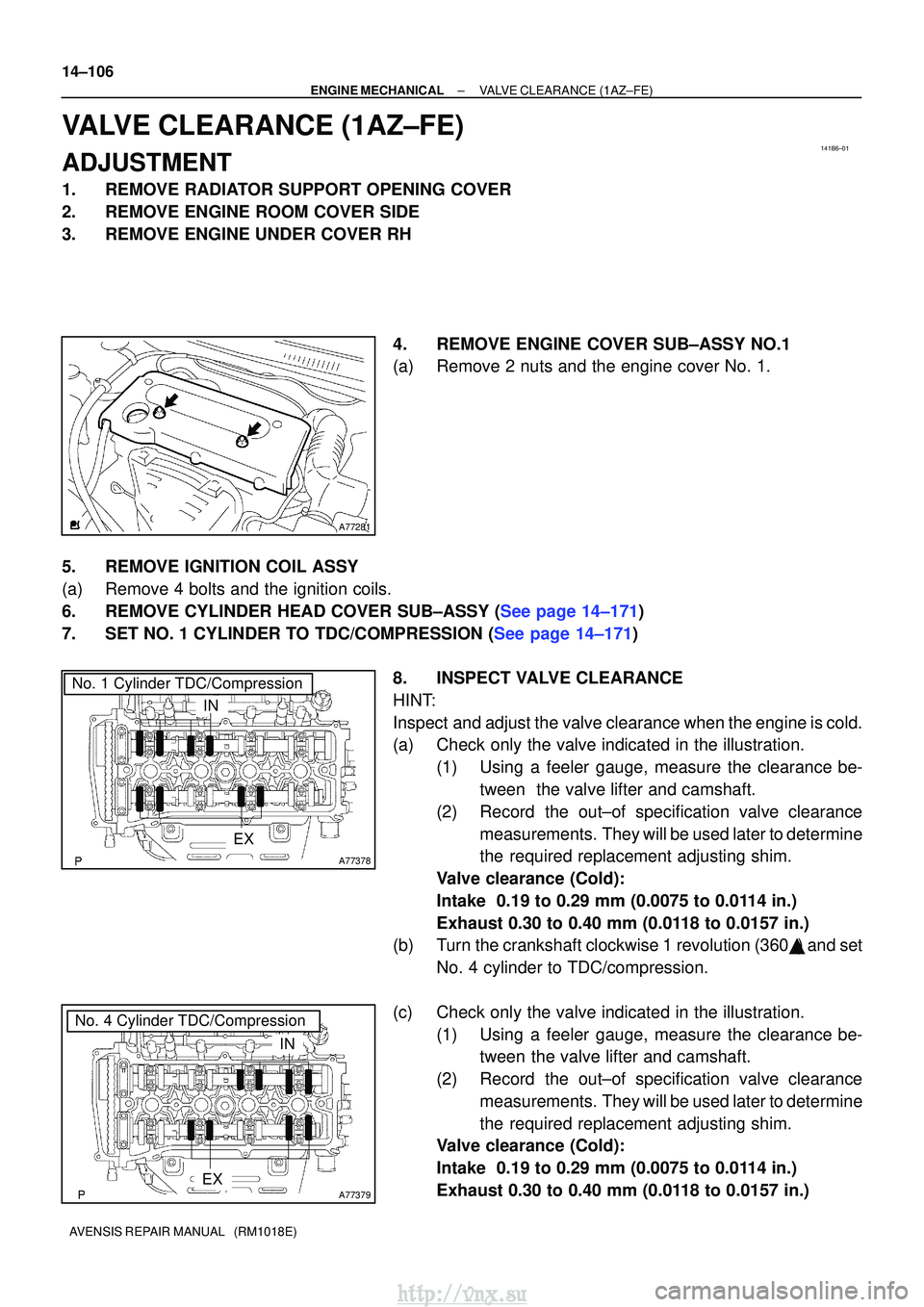
7.SET NO. 1 CYLINDER TO TDC/COMPRESSION (See page 14±171) 8. INSPECT VALVE CLEARANCE
HINT:
Inspect and adjust the valve clearance when the engine is cold.
(a) Check only the valve indicated in the illustration.(1) Using a feeler gauge, measure the clearance be-tween the valve lifter and camshaft.
(2) Record the out±of specification valve clearance measurements. They will be used later to determine
the required replacement adjusting shim.
Valve clearance (Cold):
Intake 0.19 to 0.29 mm (0.0075 to 0.0114 in.)
Exhaust 0.30 to 0.40 mm (0.0118 to 0.0157 in.)
(b) Turn the crankshaft clockwise 1 revolution (360� ) and set
No. 4 cylinder to TDC/compression.
(c) Check only the valve indicated in the illustration. (1) Using a feeler gauge, measure the clearance be-tween the valve lifter and camshaft.
(2) Record the out±of specification valve clearance measurements. They will be used later to determine
the required replacement adjusting shim.
Valve clearance (Cold):
Intake 0.19 to 0.29 mm (0.0075 to 0.0114 in.)
Exhaust 0.30 to 0.40 mm (0.0118 to 0.0157 in.)
http://vnx.su
Page 717 of 2234

Measure valve clearance = 0.44 mm (0.0173 in.)
0.44 mm (0.0173 in.) ± 0.24 mm (0.0094 in.) = 0.20 mm (0.0079 in\
.)
(Measured ± Specification = Excess clearance)
Used sh")
A01082
EXAMPLE: (Intake)
Measure valve clearance = 0.44 mm (0.0173 in.)
0.44 mm (0.0173 in.) ± 0.24 mm (0.0094 in.) = 0.20 mm (0.0079 in\
.)
(Measured ± Specification = Excess clearance)
Used shim measurement = 5.30 mm (0.2087 in.)
0.20 mm (0.0079 in.) + 5.30 mm (0.2087 in.) = 5.50 mm (0.2165 in.)\
(Excess clearance + Used shim = Ideal new shim)
Closest new shim = 5.50 mm (0.2165 in.) = Shim No. º50º
A77295
±
ENGINE MECHANICALVALVE CLEARANCE(1AZ±FE)
14±107
AVENSIS REPAIR MANUAL (RM1018E)
9.ADJUST VALVE CLEARANCE
NOTICE:
Be sure not to turn the crankshaft without the chain ten-
sioner.
(a)Set the No. 1 cylinder to TDC/compression.
(See page 14±171)
(b)Remove the chain tensioner. (See page 14±171)
(c)Remove the camshafts. (See page 14±171)
(d) Tie the timing chain with a string.
NOTICE:
Be careful not to drop anything inside the timing chain cov-
er.
(e) Remove the valve lifters.
(f) Using a micrometer, measure the thickness of the re-
moved lifter.
(g) Calculate the thickness of a new lifter so that the valve
clearance comes within the specified valve.
AThickness of new lifter
BThickness of used lifter
CMeasured valve clearance
Valve clearance:
Intake: A = B + (C ± 0.24 mm (0.0094 in.))
Exhaust: A = B + (C ± 0.35 mm (0.0138 in.))
HINT:
�Select a new lifter with a thickness as close as possible
to the calculated valves.
�Lifter are available in 35 sizes in increments of 0.020 mm
(0.0008 in.), from 5.060 mm (0.1992 in.) to 5.740 mm
(0.2260 in.).
�Identification number inside the valve lifter shows the val-
ue of the 2 decimal places. (The illustration shows 5.380
mm (0.2118 in.))
�Refer to the New Lifter Thickness table on the next 2
pages.
http://vnx.su
Page 722 of 2234
A64058
A64856
A62185
MarkMark
Mark Timing Chain
Cover Surface
Timing
Notch
A01131
±
ENGINE MECHANICAL VALVE CLEARANCE (1ZZ±FE/3ZZ±FE)
14±7
AVENSIS REPAIR MANUAL (RM1018E)
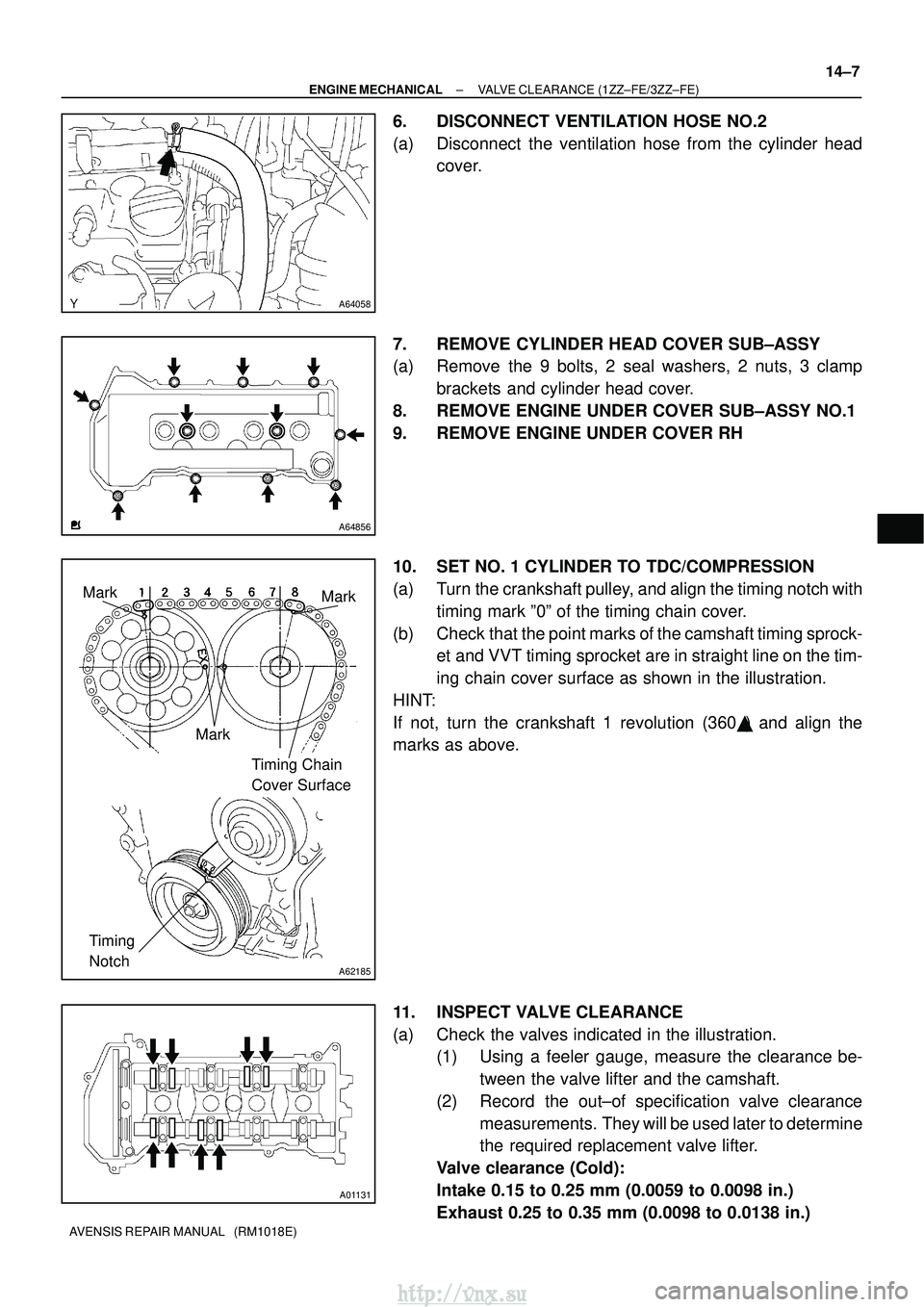
6. DISCONNECT VENTILATION HOSE NO.2
(a) Disconnect the ventilation hose from the cylinder head
cover.
7. REMOVE CYLINDER HEAD COVER SUB±ASSY
(a) Remove the 9 bolts, 2 seal washers, 2 nuts, 3 clamp brackets and cylinder head cover.
8. REMOVE ENGINE UNDER COVER SUB±ASSY NO.1
9. REMOVE ENGINE UNDER COVER RH
10. SET NO. 1 CYLINDER TO TDC/COMPRESSION
(a) Turn the crankshaft pulley, and align the timing notch with timing mark º0º of the timing chain cover.
(b) Check that the point marks of the camshaft timing sprock- et and VVT timing sprocket are in straight line on the tim-
ing chain cover surface as shown in the illustration.
HINT:
If not, turn the crankshaft 1 revolution (360 �) and align the
marks as above.
11. INSPECT VALVE CLEARANCE
(a) Check the valves indicated in the illustration. (1) Using a feeler gauge, measure the clearance be-
tween the valve lifter and the camshaft.
(2) Record the out±of specification valve clearance measurements. They will be used later to determine
the required replacement valve lifter.
Valve clearance (Cold):
Intake 0.15 to 0.25 mm (0.0059 to 0.0098 in.)
Exhaust 0.25 to 0.35 mm (0.0098 to 0.0138 in.)
http://vnx.su
Page 723 of 2234
A01132
A60622
A01045
A64005
14±8
±
ENGINE MECHANICAL VALVE CLEARANCE (1ZZ±FE/3ZZ±FE)
AVENSIS REPAIR MANUAL (RM1018E)
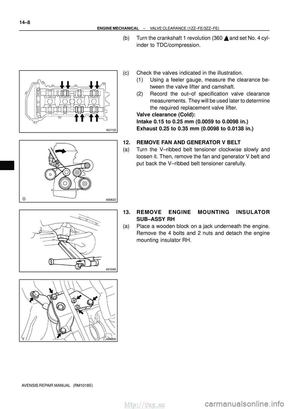
(b) Turn the crankshaft 1 revolution (360 �) and set No. 4 cyl-
inder to TDC/compression.
(c) Check the valves indicated in the illustration. (1) Using a feeler gauge, measure the clearance be-
tween the valve lifter and camshaft.
(2) Record the out±of specification valve clearance measurements. They will be used later to determine
the required replacement valve lifter.
Valve clearance (Cold):
Intake 0.15 to 0.25 mm (0.0059 to 0.0098 in.)
Exhaust 0.25 to 0.35 mm (0.0098 to 0.0138 in.)
12. REMOVE FAN AND GENERATOR V BELT
(a) Turn the V±ribbed belt tensioner clockwise slowly and loosen it. Then, remove the fan and generator V belt and
put back the V±ribbed belt tensioner carefully.
13. REMOVE ENGINE MOUNTING INSULATOR SUB±ASSY RH
(a) Place a wooden block on a jack underneath the engine. Remove the 4 bolts and 2 nuts and detach the engine
mounting insulator RH.
http://vnx.su
Page 736 of 2234
A77857
A78440
New Gasket
15±8
±
EXHAUSTEXHAUST PIPE ASSY(1AZ±FE/1AZ±FSE)
AVENSIS REPAIR MANUAL (RM1018E)
5.INSTALL EXHAUST PIPE ASSY FRONT
(a)Compression spring inspection (1)Using vernier calipers, measure the free length of
the compression spring.
Minimum length: 41.5 mm (1.634 in.)
If the free length is less than minimum, replace the compression
spring.
(b)Install a new gasket to the exhaust manifold as shown in the illustration.
(c)Install the exhaust pipe front with the 2 compression springs and 2 bolts.
Torque: 43 N �m (440 kgf�cm, 32 ft�lbf)
6.INSTALL EXHAUST PIPE ASSY CENTER
(a)Install a new gasket and the exhaust pipe center to the 2 exhaust pipe s\
upports.
(b)Tighten the 2 bolts. Torque: 43 N �m (440 kgf�cm, 32 ft�lbf)
7.INSTALL EXHAUST PIPE ASSY TAIL (See page 15±2)
8. CHECK FOR EXHAUST GAS LEAKS
9.INSTALL FLOOR PANEL BRACE FRONT (See page 15±2)
http://vnx.su
Page 740 of 2234
A77857
A78440
New Gasket
15±12
±
EXHAUST EXHAUST PIPE ASSY (1CD±FTV)
AVENSIS REPAIR MANUAL (RM1018E)
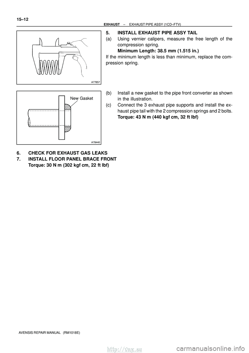
5. INSTALL EXHAUST PIPE ASSY TAIL
(a) Using vernier calipers, measure the free length of the compression spring.
Minimum Length: 38.5 mm (1.515 in.)
If the minimum length is less than minimum, replace the com-
pression spring.
(b) Install a new gasket to the pipe front converter as shown in the illustration.
(c) Connect the 3 exhaust pipe supports and install the ex- haust pipe tail with the 2 compression springs and 2 bolts.
Torque: 43 N� m (440 kgf�cm, 32 ft�lbf)
6. CHECK FOR EXHAUST GAS LEAKS
7. INSTALL FLOOR PANEL BRACE FRONT Torque: 30 N �m (302 kgf� cm, 22 ft�lbf)
http://vnx.su
Page 744 of 2234
A78492
(a)(a)
(b)
(b)
A77857
A78440
New Gasket
15±4
±
EXHAUST EXHAUST PIPE ASSY (1ZZ±FE/3ZZ±FE)
AVENSIS REPAIR MANUAL (RM1018E)
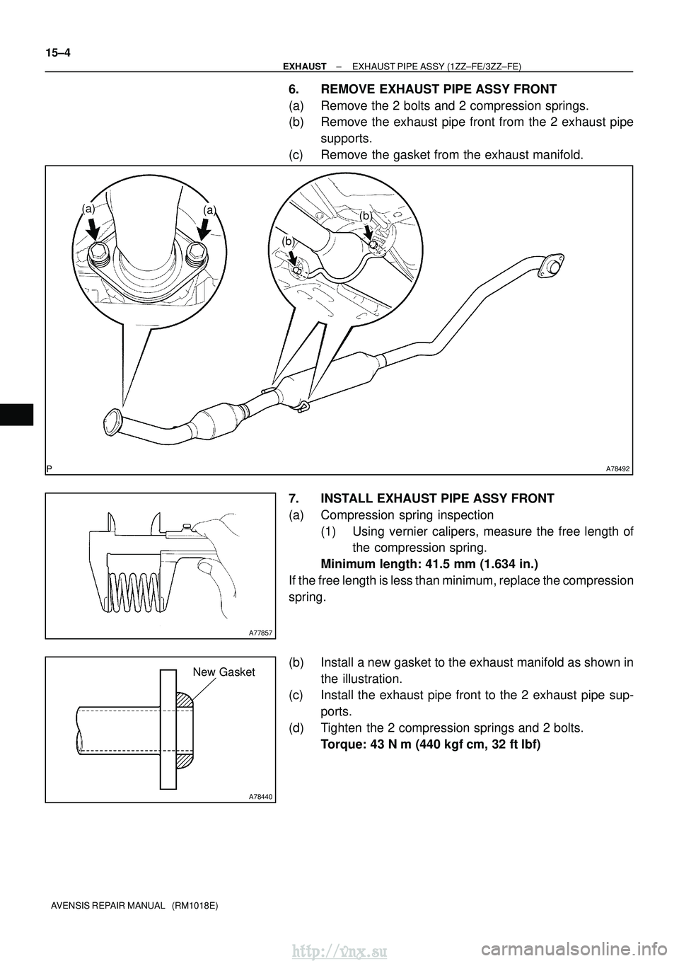
6. REMOVE EXHAUST PIPE ASSY FRONT
(a) Remove the 2 bolts and 2 compression springs.
(b) Remove the exhaust pipe front from the 2 exhaust pipe supports.
(c) Remove the gasket from the exhaust manifold.
7. INSTALL EXHAUST PIPE ASSY FRONT
(a) Compression spring inspection (1) Using vernier calipers, measure the free length ofthe compression spring.
Minimum length: 41.5 mm (1.634 in.)
If the free length is less than minimum, replace the compression
spring.
(b) Install a new gasket to the exhaust manifold as shown in the illustration.
(c) Install the exhaust pipe front to the 2 exhaust pipe sup-
ports.
(d) Tighten the 2 compression springs and 2 bolts. Torque: 43 N �m (440 kgf� cm, 32 ft�lbf)
http://vnx.su