Page 1093 of 2234
320W5±01
G24285
LHD Steering Position Type:Charcoal Canister Assy
Brake Fluid Level
Switch Connector Clutch Reservoir
Tube M/T Transaxle:Brake Booster Assy
Clip
Way
20 (204, 15)
15 (155, 11)
15 (155, 11)*1
29 (296, 21)*2
15 (155, 11)*1
29 (296, 21)*2
Brake Master
Cylinder Sub±assy
20 (204, 15)
Engin Room Relay Block
RHD Steering Position Type: Air Cleaner Cap Sub±assy
Brake Fluid Level
Switch Connector Brake Master
Cylinder Sub±assy
Clip
Accelerator Control
Cable Support
20 (204, 15)
*1
w/ ABS:*2 w/ VSC:N�m (kgf� cm, ft�lbf) : Specified torque
15 (155, 11)*1
29 (296, 21)*2
15 (155, 11)*1
29 (296, 21)*2
Clutch Reservoir
Tube M/T Transaxle:
Brake Booster Assy
5.4 (55, 48 in.� lbf)
Fuel Filter Assy Diesel Engin Type:
±
BRAKE BRAKE MASTER CYLINDER SUB±ASSY
32±11
AVENSIS REPAIR MANUAL (RM1018E)
BRAKE MASTER CYLINDER SUB±ASSY
COMPONENTS
http://vnx.su
Page 1095 of 2234
320W6±01
G24218
G24217
F45393
±
BRAKE BRAKE MASTER CYLINDER SUB±ASSY
32±13
AVENSIS REPAIR MANUAL (RM1018E)
REPLACEMENT
NOTICE:
Do not adjust the brake booster push rod.
1. DRAIN BRAKE FLUID
NOTICE:
Wash the brake fluid off immediately if it adheres to any painted surface\
.
2. REMOVE ENGINE ROOM RELAY BLOCK (LHD STEERING POSITION TYPE)
3. REMOVE AIR CLEANER CAP SUB±ASSY (LHD STEERING POSITION TYPE)
4. REMOVE CHARCOAL CANISTER ASSY (LHD STEERING POSITION TYPE)
5. REMOVE FUEL FILTER ASSY (LHD STEERING POSITION TYPE)
(a) Diesal engine type:
Remove the fuel filter assy with the 3 bolts.
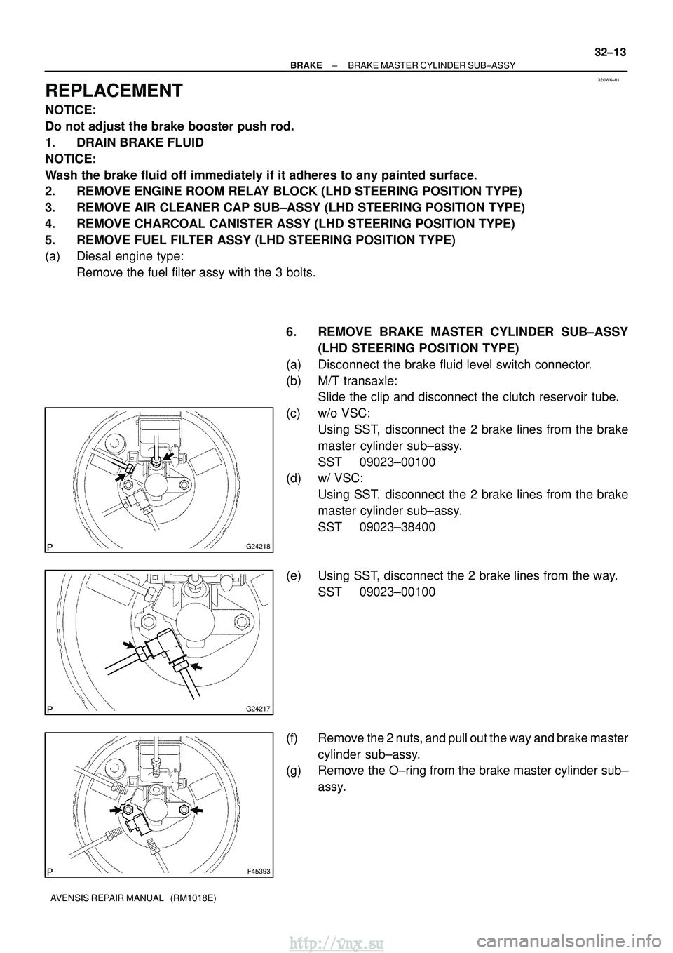
6. REMOVE BRAKE MASTER CYLINDER SUB±ASSY(LHD STEERING POSITION TYPE)
(a) Disconnect the brake fluid level switch connector.
(b) M/T transaxle: Slide the clip and disconnect the clutch reservoir tube.
(c) w/o VSC: Using SST, disconnect the 2 brake lines from the brake
master cylinder sub±assy.
SST 09023±00100
(d) w/ VSC:
Using SST, disconnect the 2 brake lines from the brake
master cylinder sub±assy.
SST 09023±38400
(e) Using SST, disconnect the 2 brake lines from the way. SST 09023±00100
(f) Remove the 2 nuts, and pull out the way and brake master cylinder sub±assy.
(g) Remove the O±ring from the brake master cylinder sub±
assy.
http://vnx.su
Page 1096 of 2234
G24225
F45394
F45395Lithium soap base glycol grease
Grommets
Retainer
Washer
32±14
±
BRAKE BRAKE MASTER CYLINDER SUB±ASSY
AVENSIS REPAIR MANUAL (RM1018E)
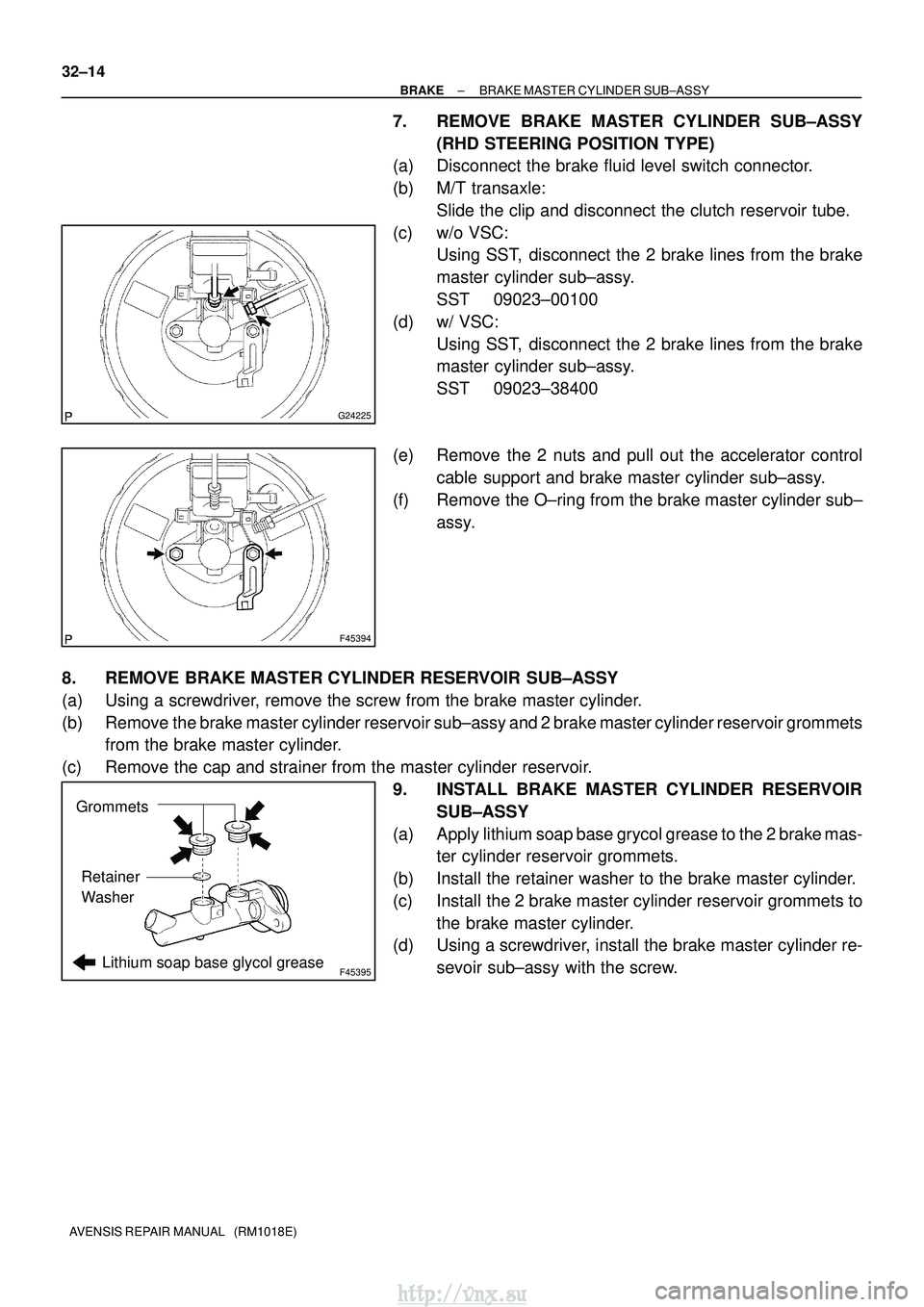
7. REMOVE BRAKE MASTER CYLINDER SUB±ASSY (RHD STEERING POSITION TYPE)
(a) Disconnect the brake fluid level switch connector.
(b) M/T transaxle:
Slide the clip and disconnect the clutch reservoir tube.
(c) w/o VSC: Using SST, disconnect the 2 brake lines from the brake
master cylinder sub±assy.
SST 09023±00100
(d) w/ VSC: Using SST, disconnect the 2 brake lines from the brake
master cylinder sub±assy.
SST 09023±38400
(e) Remove the 2 nuts and pull out the accelerator control cable support and brake master cylinder sub±assy.
(f) Remove the O±ring from the brake master cylinder sub± assy.
8. REMOVE BRAKE MASTER CYLINDER RESERVOIR SUB±ASSY
(a) Using a screwdriver, remove the screw from the brake master cylinder.
(b) Remove the brake master cylinder reservoir sub±assy and 2 brake master cylinder reservoir grommets from the brake master cylinder.
(c) Remove the cap and strainer from the master cylinder reservoir. 9. INSTALL BRAKE MASTER CYLINDER RESERVOIRSUB±ASSY
(a) Apply lithium soap base grycol grease to the 2 brake mas- ter cylinder reservoir grommets.
(b) Install the retainer washer to the brake master cylinder.
(c) Install the 2 brake master cylinder reservoir grommets to the brake master cylinder.
(d) Using a screwdriver, install the brake master cylinder re-
sevoir sub±assy with the screw.
http://vnx.su
Page 1097 of 2234
F45393
G24217
G24218
F45394
±
BRAKE BRAKE MASTER CYLINDER SUB±ASSY
32±15
AVENSIS REPAIR MANUAL (RM1018E)
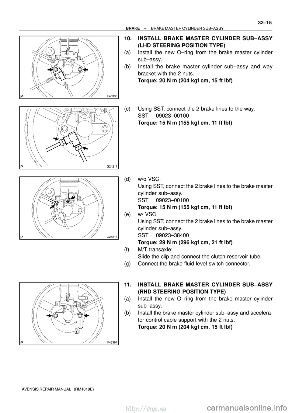
10. INSTALL BRAKE MASTER CYLINDER SUB±ASSY
(LHD STEERING POSITION TYPE)
(a) Install the new O±ring from the brake master cylinder
sub±assy.
(b) Install the brake master cylinder sub±assy and way bracket with the 2 nuts.
Torque: 20 N �m (204 kgf� cm, 15 ft�lbf)
(c) Using SST, connect the 2 brake lines to the way. SST 09023±00100
Torque: 15 N �m (155 kgf� cm, 11 ft�lbf)
(d) w/o VSC: Using SST, connect the 2 brake lines to the brake master
cylinder sub±assy.
SST 09023±00100
Torque: 15 N �m (155 kgf� cm, 11 ft�lbf)
(e) w/ VSC: Using SST, connect the 2 brake lines to the brake master
cylinder sub±assy.
SST 09023±38400
Torque: 29 N �m (296 kgf� cm, 21 ft�lbf)
(f) M/T transaxle: Slide the clip and connect the clutch reservoir tube.
(g) Connect the brake fluid level switch connector.
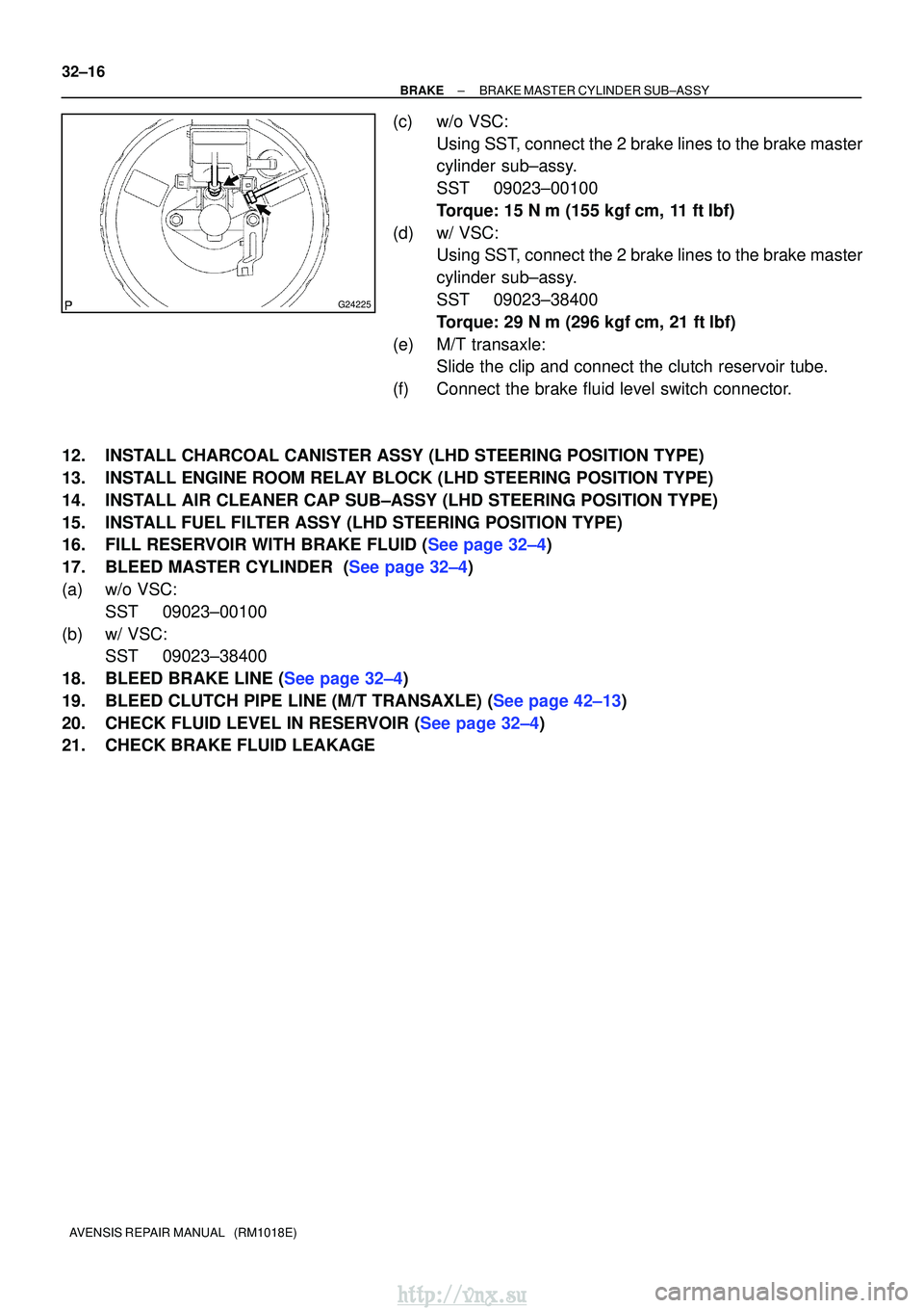
11. INSTALL BRAKE MASTER CYLINDER SUB±ASSY (RHD STEERING POSITION TYPE)
(a) Install the new O±ring from the brake master cylinder
sub±assy.
(b) Install the brake master cylinder sub±assy and accelera- tor control cable support with the 2 nuts.
Torque: 20 N �m (204 kgf� cm, 15 ft�lbf)
http://vnx.su
Page 1098 of 2234
G24225
32±16
±
BRAKE BRAKE MASTER CYLINDER SUB±ASSY
AVENSIS REPAIR MANUAL (RM1018E)
(c) w/o VSC: Using SST, connect the 2 brake lines to the brake master
cylinder sub±assy.
SST 09023±00100
Torque: 15 N �m (155 kgf� cm, 11 ft�lbf)
(d) w/ VSC: Using SST, connect the 2 brake lines to the brake master
cylinder sub±assy.
SST 09023±38400
Torque: 29 N �m (296 kgf� cm, 21 ft�lbf)
(e) M/T transaxle: Slide the clip and connect the clutch reservoir tube.
(f) Connect the brake fluid level switch connector.
12. INSTALL CHARCOAL CANISTER ASSY (LHD STEERING POSITION TYPE)
13. INSTALL ENGINE ROOM RELAY BLOCK (LHD STEERING POSITION TYPE)
14. INSTALL AIR CLEANER CAP SUB±ASSY (LHD STEERING POSITION TYPE)
15. INSTALL FUEL FILTER ASSY (LHD STEERING POSITION TYPE)
16.FILL RESERVOIR WITH BRAKE FLUID (See page 32±4)
17.BLEED MASTER CYLINDER (See page 32±4)
(a) w/o VSC: SST 09023±00100
(b) w/ VSC: SST 09023±38400
18.BLEED BRAKE LINE (See page 32±4)
19.BLEED CLUTCH PIPE LINE (M/T TRANSAXLE) (See page 42±13)
20.CHECK FLUID LEVEL IN RESERVOIR (See page 32±4)
21. CHECK BRAKE FLUID LEAKAGE
http://vnx.su
Page 1105 of 2234
3201B±12
32±2
±
BRAKE BRAKE SYSTEM
AVENSIS REPAIR MANUAL (RM1018E)
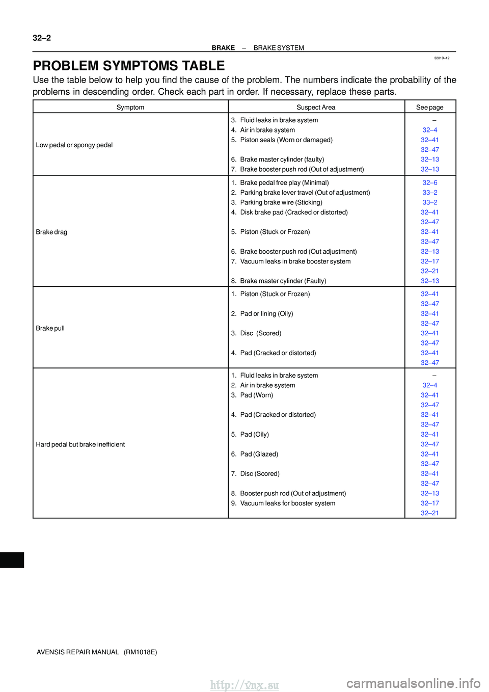
PROBLEM SYMPTOMS TABLE
Use the table below to help you find the cause of the problem. The numbers \
indicate the probability of the
problems in descending order. Check each part in order. If necessary, replace these parts.
SymptomSuspect AreaSee page
Low pedal or spongy pedal
3. Fluid leaks in brake system
4. Air in brake system
5. Piston seals (Worn or damaged)
6. Brake master cylinder (faulty)
7. Brake booster push rod (Out of adjustment) ±
32±4
32±41
32±47
32±13
32±13
Brake drag
1. Brake pedal free play (Minimal)
2. Parking brake lever travel (Out of adjustment)
3. Parking brake wire (Sticking)
4. Disk brake pad (Cracked or distorted)
5. Piston (Stuck or Frozen)
6. Brake booster push rod (Out adjustment)
7. Vacuum leaks in brake booster system
8. Brake master cylinder (Faulty)32±6
33±2
33±2
32±41
32±47
32±41
32±47
32±13
32±17
32±21
32±13
Brake pull
1. Piston (Stuck or Frozen)
2. Pad or lining (Oily)
3. Disc (Scored)
4. Pad (Cracked or distorted) 32±41
32±47
32±41
32±47
32±41
32±47
32±41
32±47
Hard pedal but brake inefficient
1. Fluid leaks in brake system
2. Air in brake system
3. Pad (Worn)
4. Pad (Cracked or distorted)
5. Pad (Oily)
6. Pad (Glazed)
7. Disc (Scored)
8. Booster push rod (Out of adjustment)
9. Vacuum leaks for booster system ±
32±4
32±41
32±47
32±41
32±47
32±41
32±47
32±41
32±47
32±41
32±47
32±13
32±17
32±21
http://vnx.su
Page 1108 of 2234
320W1±01
F45421
Union Bolt
G23232
F45419
Cylinder Slide Pin
F45417
Cylinder Slide Bush
Cylinder Slide Pin (No.2)
±
BRAKE FRONT BRAKE
32±41
AVENSIS REPAIR MANUAL (RM1018E)
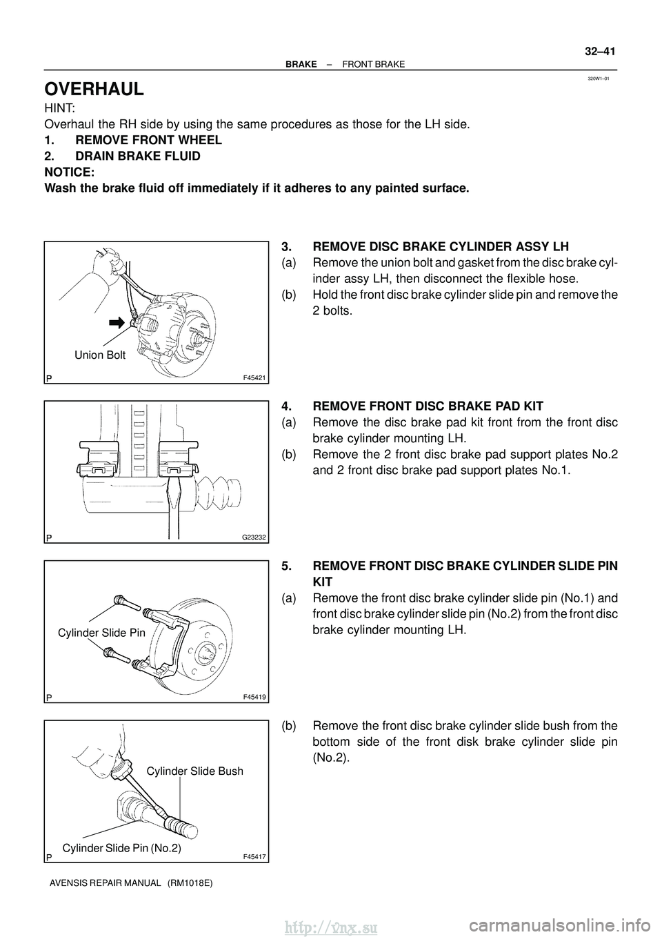
OVERHAUL
HINT:
Overhaul the RH side by using the same procedures as those for the LH side.
1. REMOVE FRONT WHEEL
2. DRAIN BRAKE FLUID
NOTICE:
Wash the brake fluid off immediately if it adheres to any painted surface\
.
3. REMOVE DISC BRAKE CYLINDER ASSY LH
(a) Remove the union bolt and gasket from the disc brake cyl-inder assy LH, then disconnect the flexible hose.
(b) Hold the front disc brake cylinder slide pin and remove the 2 bolts.
4. REMOVE FRONT DISC BRAKE PAD KIT
(a) Remove the disc brake pad kit front from the front disc brake cylinder mounting LH.
(b) Remove the 2 front disc brake pad support plates No.2 and 2 front disc brake pad support plates No.1.
5. REMOVE FRONT DISC BRAKE CYLINDER SLIDE PIN KIT
(a) Remove the front disc brake cylinder slide pin (No.1) and front disc brake cylinder slide pin (No.2) from the front disc
brake cylinder mounting LH.
(b) Remove the front disc brake cylinder slide bush from the bottom side of the front disk brake cylinder slide pin
(No.2).
http://vnx.su
Page 1109 of 2234
F45420
Front Disc Brake Cylinder MountingBush Dust Boot
F45418
C64095
G23222
G23223
32±42
±
BRAKE FRONT BRAKE
AVENSIS REPAIR MANUAL (RM1018E)
6. REMOVE FRONT DISC BRAKE BUSH DUST BOOT
(a) Remove the 2 front disc brake bush dust boots from the front disc brake cylinder mounting LH.
7. REMOVE FRONT DISC BRAKE CYLINDER MOUNTING LH
(a) Remove the 2 bolts and front disc brake cylinder mount- ing LH.
8. REMOVE FRONT DISC BRAKE PISTON
(a) Place a shop rug between the front disc brake piston and the disc brake cylinder assy LH.
(b) Use compressed air to remove the front disc brake piston from the disc brake cylinder assy LH.
CAUTION:
Do not place your fingers in front of the piston when using
compressed air.
NOTICE:
Do not spatter the brake fluid.
9. REMOVE CYLINDER BOOT
(a) Using a screwdriver, remove the cylinder boot.
10. REMOVE PISTON SEAL
(a) Using a screwdriver, remove the piston seal.
NOTICE:
Do not damage the inner cylinder and cylinder groove.
http://vnx.su