Page 1064 of 2234
30093±02
������F45576
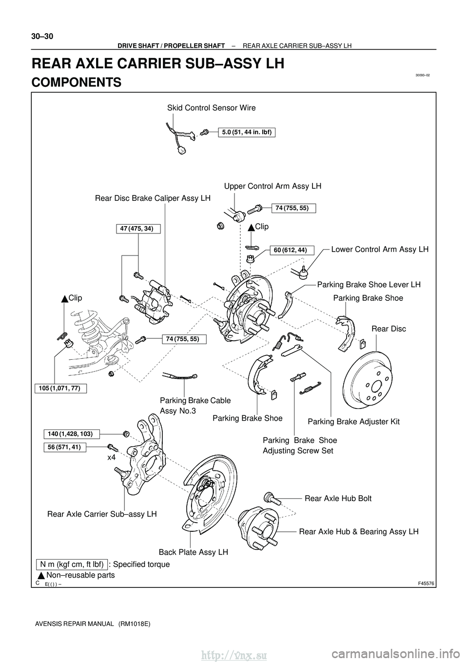
Skid Control Sensor Wire
5.0 (51, 44 in.�lbf)
Upper Control Arm Assy LH
�Clip
74 (755, 55)
60 (612, 44)Lower Control Arm Assy LH
Parking Brake Shoe
Rear Disc
47 (475, 34)
Rear Disc Brake Caliper Assy LH
� Clip
105 (1,071, 77)
Parking Brake Shoe
140 (1,428, 103)
56 (571, 41)
Rear Axle Carrier Sub±assy LH
Rear Axle Hub & Bearing Assy LH
Rear Axle Hub Bolt
x4
N
�m (kgf� cm, ft�lbf) : Specified torque
� Non±reusable parts Parking Brake Cable
Assy No.3
Parking Brake Shoe
Adjusting Screw Set
Parking Brake Adjuster Kit
Parking Brake Shoe Lever LH
74 (755, 55)
Back Plate Assy LH
30±30
±
DRIVE SHAFT / PROPELLER SHAFT REAR AXLE CARRIER SUB±ASSY LH
AVENSIS REPAIR MANUAL (RM1018E)
REAR AXLE CARRIER SUB±ASSY LH
COMPONENTS
http://vnx.su
Page 1065 of 2234
300JZ±01
������F45267
F44818
������F45752
SST
±
DRIVE SHAFT / PROPELLER SHAFT REAR AXLE CARRIER SUB±ASSY LH
30±31
AVENSIS REPAIR MANUAL (RM1018E)
REPLACEMENT
HINT:
Replace the RH side by the same procedures as the LH side.
1. INSPECT REAR AXLE CARRIER SUB±ASSY LH
(a) Check that there is no looseness on the ball joint by shaking the lower arm up and down with a force
of 294 N (30kgf, 66 lbf).
2. REMOVE REAR WHEEL
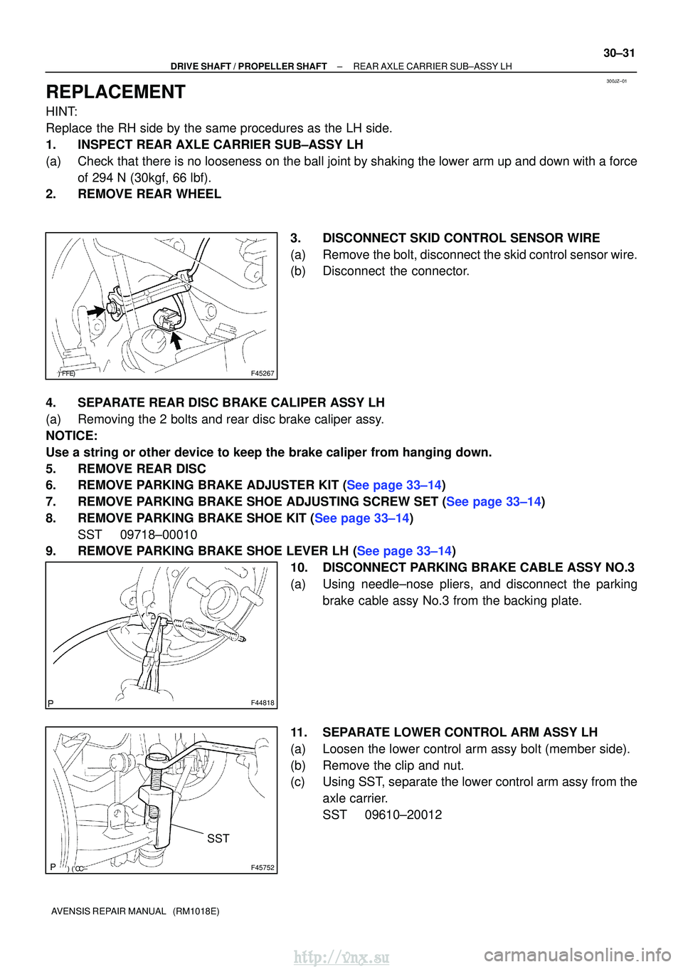
3. DISCONNECT SKID CONTROL SENSOR WIRE
(a) Remove the bolt, disconnect the skid control sensor wire.
(b) Disconnect the connector.
4. SEPARATE REAR DISC BRAKE CALIPER ASSY LH
(a) Removing the 2 bolts and rear disc brake caliper assy.
NOTICE:
Use a string or other device to keep the brake caliper from hanging down\
.
5. REMOVE REAR DISC
6.REMOVE PARKING BRAKE ADJUSTER KIT (See page 33±14)
7.REMOVE PARKING BRAKE SHOE ADJUSTING SCREW SET (See page 33±14)
8.REMOVE PARKING BRAKE SHOE KIT (See page 33±14) SST 09718±00010
9.REMOVE PARKING BRAKE SHOE LEVER LH (See page 33±14)
10. DISCONNECT PARKING BRAKE CABLE ASSY NO.3
(a) Using needle±nose pliers, and disconnect the parkingbrake cable assy No.3 from the backing plate.
11. SEPARATE LOWER CONTROL ARM ASSY LH
(a) Loosen the lower control arm assy bolt (member side).
(b) Remove the clip and nut.
(c) Using SST, separate the lower control arm assy from the axle carrier.
SST 09610±20012
http://vnx.su
Page 1068 of 2234
G21543
F44820
������F45267
30±34
±
DRIVE SHAFT / PROPELLER SHAFTREAR AXLE CARRIER SUB±ASSY LH
AVENSIS REPAIR MANUAL (RM1018E)
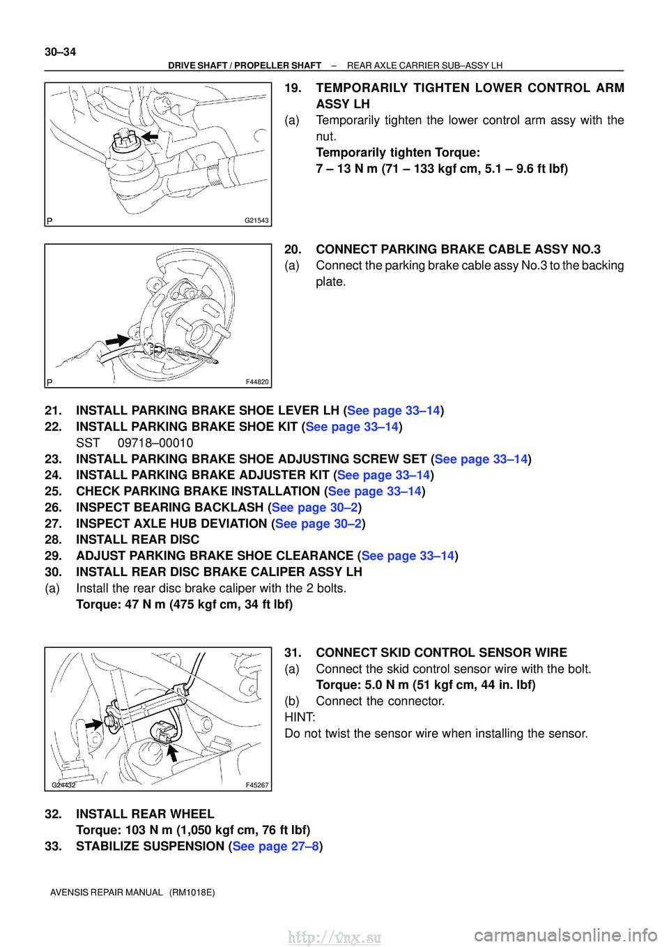
19.TEMPORARILY TIGHTEN LOWER CONTROL ARM ASSY LH
(a)Temporarily tighten the lower control arm assy with the
nut.
Temporarily tighten Torque:
7 ± 13 N�m (71 ± 133 kgf �cm, 5.1 ± 9.6 ft�lbf)
20.CONNECT PARKING BRAKE CABLE ASSY NO.3
(a)Connect the parking brake cable assy No.3 to the backing plate.
21.INSTALL PARKING BRAKE SHOE LEVER LH (See page 33±14)
22.INSTALL PARKING BRAKE SHOE KIT (See page 33±14) SST 09718±00010
23.INSTALL PARKING BRAKE SHOE ADJUSTING SCREW SET (See page 33±14)
24.INSTALL PARKING BRAKE ADJUSTER KIT (See page 33±14)
25.CHECK PARKING BRAKE INSTALLATION (See page 33±14)
26.INSPECT BEARING BACKLASH (See page 30±2)
27.INSPECT AXLE HUB DEVIATION (See page 30±2)
28. INSTALL REAR DISC
29.ADJUST PARKING BRAKE SHOE CLEARANCE (See page 33±14)
30. INSTALL REAR DISC BRAKE CALIPER ASSY LH
(a) Install the rear disc brake caliper with the 2 bolts. Torque: 47 N �m (475 kgf� cm, 34 ft�lbf)
31. CONNECT SKID CONTROL SENSOR WIRE
(a) Connect the skid control sensor wire with the bolt. Torque: 5.0 N �m (51 kgf �cm, 44 in. �lbf)
(b) Connect the connector.
HINT:
Do not twist the sensor wire when installing the sensor.
32. INSTALL REAR WHEEL Torque: 103 N� m (1,050 kgf�cm, 76 ft �lbf)
33.STABILIZE SUSPENSION (See page 27±8)
http://vnx.su
Page 1140 of 2234
������F45077
SST
F44822
SST
R00311
BR0828
F42661
±
PARKING BRAKE PARKING BRAKE ASSY
33±15
AVENSIS REPAIR MANUAL (RM1018E)
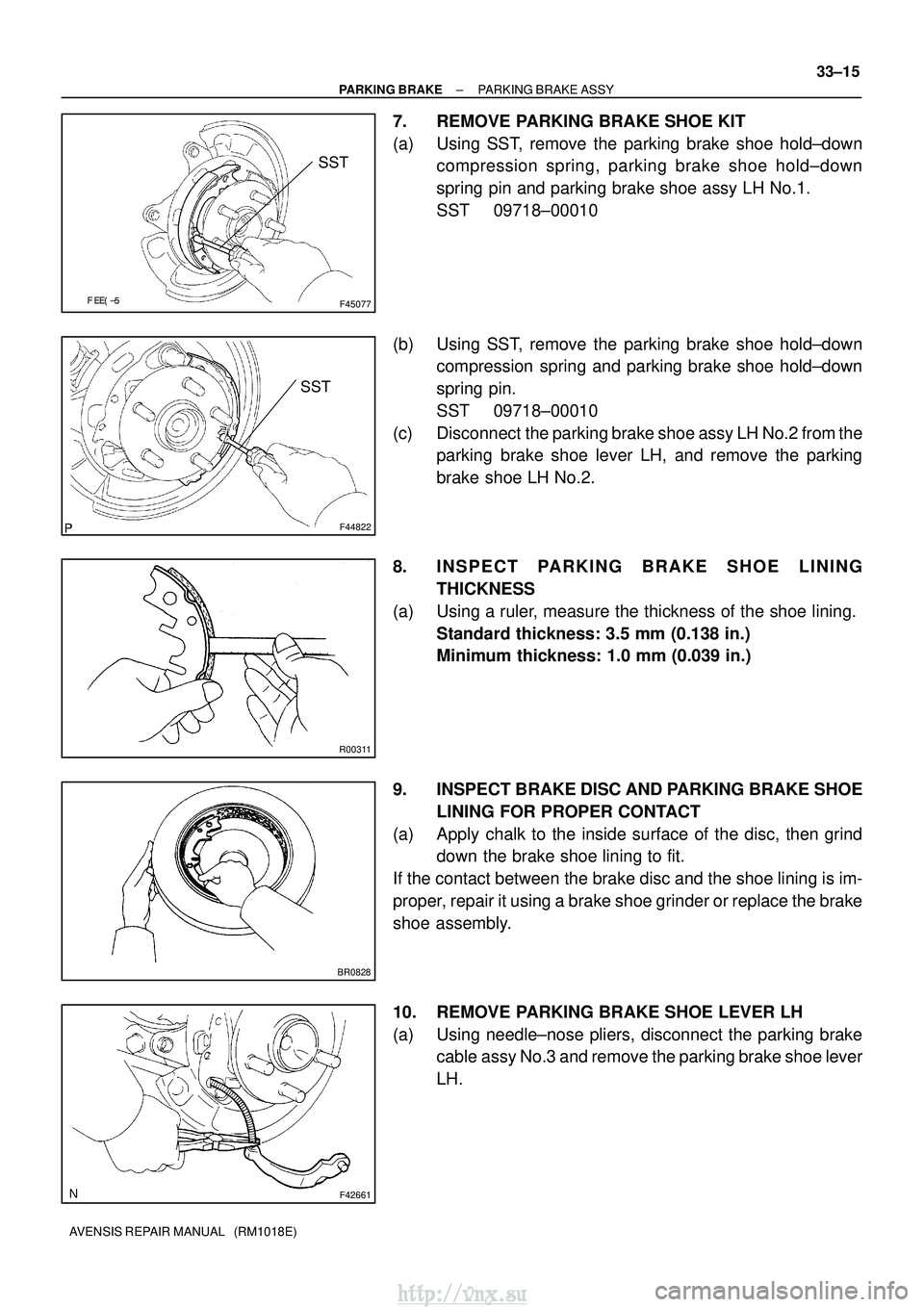
7. REMOVE PARKING BRAKE SHOE KIT
(a) Using SST, remove the parking brake shoe hold±down
compression spring, parking brake shoe hold±down
spring pin and parking brake shoe assy LH No.1.
SST 09718±00010
(b) Using SST, remove the parking brake shoe hold±down compression spring and parking brake shoe hold±down
spring pin.
SST 09718±00010
(c) Disconnect the parking brake shoe assy LH No.2 from the parking brake shoe lever LH, and remove the parking
brake shoe LH No.2.
8. INSPECT PARKING B RAKE SHOE LINING
THICKNESS
(a) Using a ruler, measure the thickness of the shoe lining. Standard thickness: 3.5 mm (0.138 in.)
Minimum thickness: 1.0 mm (0.039 in.)
9. INSPECT BRAKE DISC AND PARKING BRAKE SHOE LINING FOR PROPER CONTACT
(a) Apply chalk to the inside surface of the disc, then grind down the brake shoe lining to fit.
If the contact between the brake disc and the shoe lining is im-
proper, repair it using a brake shoe grinder or replace the brake
shoe assembly.
10. REMOVE PARKING BRAKE SHOE LEVER LH
(a) Using needle±nose pliers, disconnect the parking brake cable assy No.3 and remove the parking brake shoe lever
LH.
http://vnx.su
Page 1141 of 2234
\b�����F44709
F42661
C80704
F44822
SST
\b�����F44705
SST
33±16
±
PARKING BRAKE PARKING BRAKE ASSY
AVENSIS REPAIR MANUAL (RM1018E)
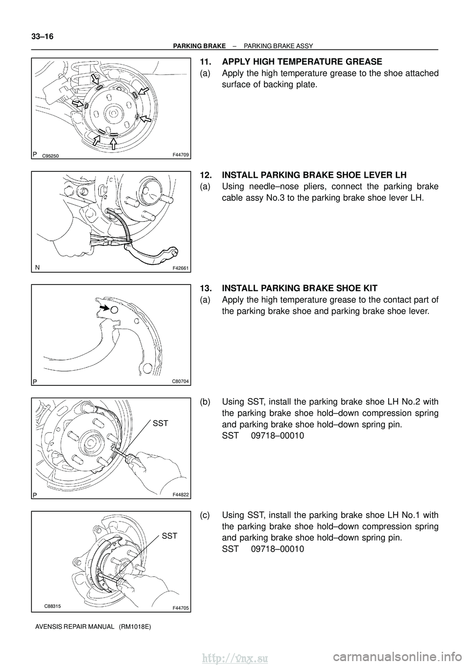
11. APPLY HIGH TEMPERATURE GREASE
(a) Apply the high temperature grease to the shoe attached surface of backing plate.
12. INSTALL PARKING BRAKE SHOE LEVER LH
(a) Using needle±nose pliers, connect the parking brake cable assy No.3 to the parking brake shoe lever LH.
13. INSTALL PARKING BRAKE SHOE KIT
(a) Apply the high temperature grease to the contact part of the parking brake shoe and parking brake shoe lever.
(b) Using SST, install the parking brake shoe LH No.2 with the parking brake shoe hold±down compression spring
and parking brake shoe hold±down spring pin.
SST 09718±00010
(c) Using SST, install the parking brake shoe LH No.1 with the parking brake shoe hold±down compression spring
and parking brake shoe hold±down spring pin.
SST 09718±00010
http://vnx.su
Page 1145 of 2234
3306A±03
F44814
Parking Brake Lever Sub±assy
Parking Brake Switch Connector Lock Nut
5.0 (51, 44 in.�
lbf)
Adjusting Nut
Parking Brake Cable Assy No.1 Equalizer
Front Floor Heat
Insulator No.1 Front Floor Heat
Insulator No.2
Exhaust Pipe Assy Front Exhaust Pipe Support
Exhaust Pipe Support
N�m (kgf� cm, ft�lbf)
: Specified torque Front Floor Panel Brace
Gasoline Engine Type: Gasoline Engine Type:
5.5 (56, 49 in.�
lbf)
5.5 (56, 49 in.�lbf)
5.5 (56, 49 in. �lbf)
13 (127, 9)
43 (440, 32)
A/T Transaxle type:
Console Panel Sub±Assy Upper
M/T Transaxle type:
Console Panel Sub±Assy Upper Floor Shift Shift
Lever Knob
Sub±Assy
Console Box Assy RR
Console Panel Sub±Assy Lower
43 (440, 32)
A/T Transaxle
M/T Transaxle
M/T Transaxle
43 (440, 32)30 (302, 21)
33±6
±
PARKING BRAKE PARKING BRAKE CABLE ASSY NO.1
AVENSIS REPAIR MANUAL (RM1018E)
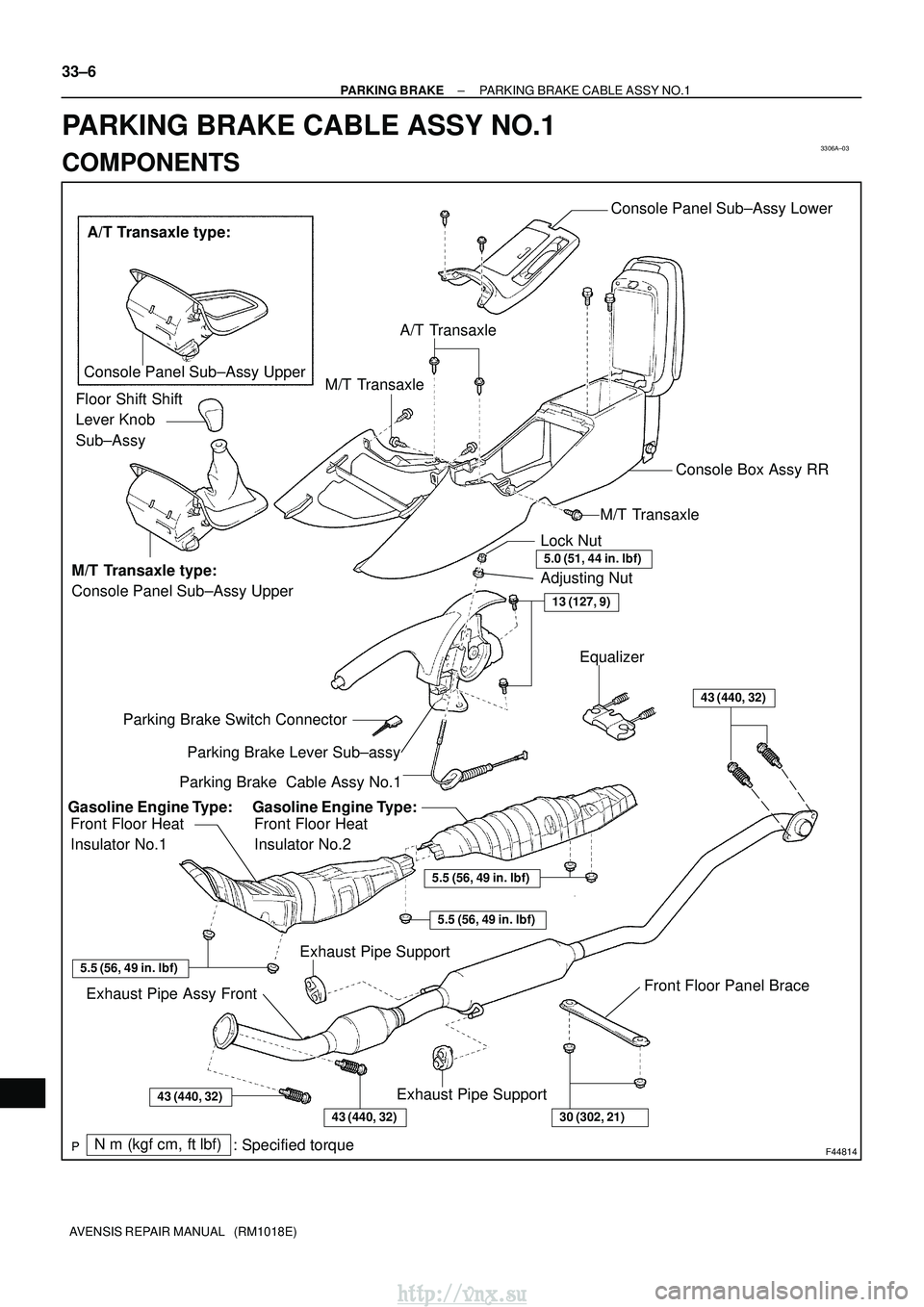
PARKING BRAKE CABLE ASSY NO.1
COMPONENTS
http://vnx.su
Page 1146 of 2234
3306B±03
F44815
F44816
±
PARKING BRAKE PARKING BRAKE CABLE ASSY NO.1
33±7
AVENSIS REPAIR MANUAL (RM1018E)
REPLACEMENT
1. REMOVE SHIFT LEVER KNOB SUB±ASSY (M/T TRANSAXLE)
(See page 41±11)
2.REMOVE CONSOLE PANEL SUB±ASSY UPPER (See page 71±11)
3.REMOVE CONSOLE PANEL SUB±ASSY LOWER (See page 71±11)
4.REMOVE CONSOLE BOX ASSY RR (See page 71±11)
5.REMOVE PARKING BRAKE LEVER SUB±ASSY (See page 33±4)
6. REMOVE EXHAUST PIPE ASSY FRONT 1ZZ±FE/3ZZ±FE ENGINE TYPE: See page 15±2
1AZ±FE/1AZ±FSE ENGINE TYPE: See page 15±7
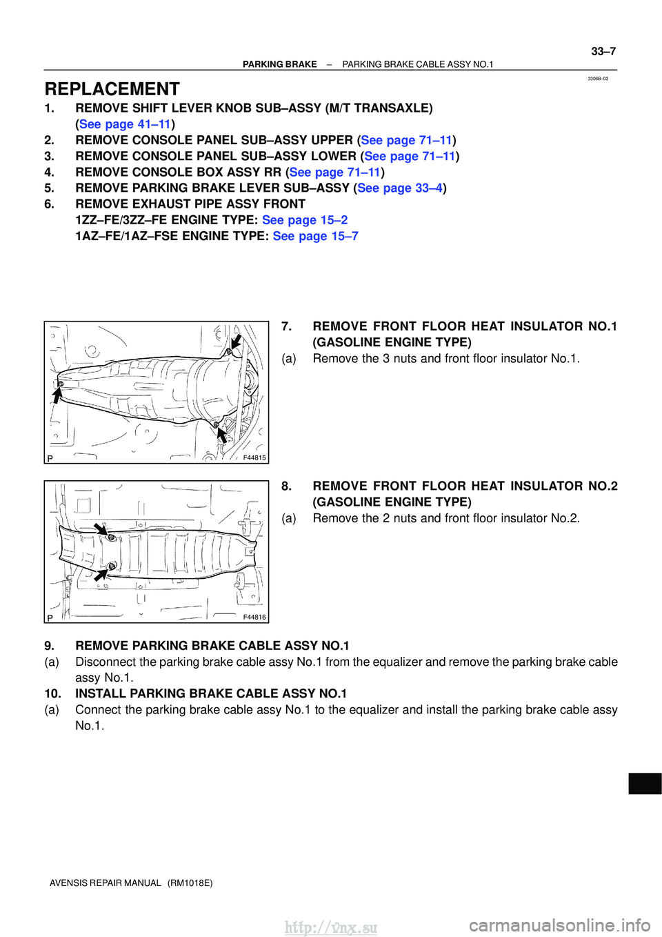
7. REMOVE FRONT FLOOR HEAT INSULATOR NO.1(GASOLINE ENGINE TYPE)
(a) Remove the 3 nuts and front floor insulator No.1.
8. REMOVE FRONT FLOOR HEAT INSULATOR NO.2 (GASOLINE ENGINE TYPE)
(a) Remove the 2 nuts and front floor insulator No.2.
9. REMOVE PARKING BRAKE CABLE ASSY NO.1
(a) Disconnect the parking brake cable assy No.1 from the equalizer and remove the parking brake cable assy No.1.
10. INSTALL PARKING BRAKE CABLE ASSY NO.1
(a) Connect the parking brake cable assy No.1 to the equalizer and install the park\
ing brake cable assy No.1.
http://vnx.su
Page 1147 of 2234
F44816
F44815
33±8
±
PARKING BRAKE PARKING BRAKE CABLE ASSY NO.1
AVENSIS REPAIR MANUAL (RM1018E)
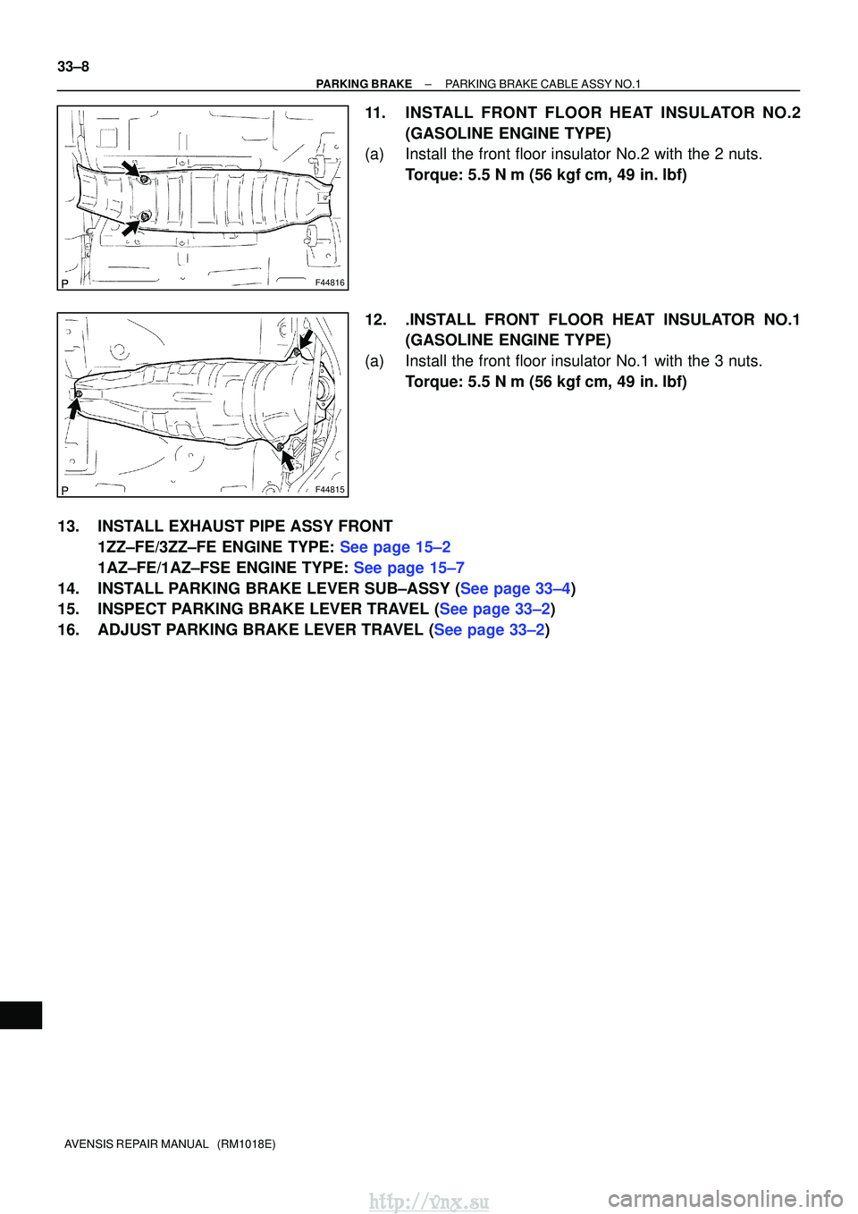
11. INSTALL FRONT FLOOR HEAT INSULATOR NO.2 (GASOLINE ENGINE TYPE)
(a) Install the front floor insulator No.2 with the 2 nuts.
Torque: 5.5 N �m (56 kgf �cm, 49 in. �lbf)
12. .INSTALL FRONT FLOOR HEAT INSULATOR NO.1 (GASOLINE ENGINE TYPE)
(a) Install the front floor insulator No.1 with the 3 nuts. Torque: 5.5 N �m (56 kgf �cm, 49 in. �lbf)
13. INSTALL EXHAUST PIPE ASSY FRONT 1ZZ±FE/3ZZ±FE ENGINE TYPE: See page 15±2
1AZ±FE/1AZ±FSE ENGINE TYPE: See page 15±7
14.INSTALL PARKING BRAKE LEVER SUB±ASSY (See page 33±4)
15.INSPECT PARKING BRAKE LEVER TRAVEL (See page 33±2)
16.ADJUST PARKING BRAKE LEVER TRAVEL (See page 33±2)
http://vnx.su