Page 367 of 2234

11±31
AVENSIS REPAIR MANUAL (RM1018E)
(b) Observe the following precautions when removin")
A60083
Fuel Pipe
Clamp No.1
AA
B12941
B12944
A82344
Vinyl Bag or plastic Bag
±
FUEL FUEL SYSTEM (1AZ±FSE)
11±31
AVENSIS REPAIR MANUAL (RM1018E)
(b) Observe the following precautions when removing and
installing fuel injectors.
NOTICE:
Never reuse the O±ring.
(1) When installing a new O±ring to the injector, becareful not to damage the injector.
(2) Coat the new O±ring with grease or gasoline before
installing. Never use engine oil, gear oil or brake oil.
(c) Observe these following precautions when disconnecting the fuel tube connector (quick type).
(1) Remove the fuel pipe clamp No.1.
(2) Check that there is no dirt or mud on the pipe and
around the connector before disconnecting them.
Clean them if necessary.
(3) Disconnect the connector from the hose while pinching part A with fingers as shown in the illustra-
tion.
(4) When the connector and the pipe are stuck, push and pull the connector to release and pull the con-
nector out from the pipe carefully.
(5) Inspect that there is no dirt or mud on the sealing
surface of the disconnected pipe. Clean it away if
necessary.
(6) To prevent the disconnected pipe and connector from being damaged and foreign objects from being
introduced, cover them with a vinyl or plastic bag.
http://vnx.su
Page 368 of 2234
B16534Push
B16535Pull
11±32
±
FUELFUEL SYSTEM(1AZ±FSE)
AVENSIS REPAIR MANUAL (RM1018E)
(d)Observe these precautions when connecting the fuel tube connectors (Quick Type):
(1)Check that there is no damage or foreign objects inthe connected part of the pipe.
(2)Match the axis of the connector with the axis of the pipe, and push into the connector until the connec-
tor makes a ºclickº sound. If the connection is tight,
apply little amount of fresh engine oil on the tip of the
pipe.
(3)After having finished the connection, check if the pipe and the connector are securely connected by
pulling on them.
(4)Check for fuel leaks.
4.CHECK FOR FUEL LEAKS
(a)Check that there are no fuel leaks after doing maintenance anywhere on t\
he fuel system. (See page 11±33)
http://vnx.su
Page 495 of 2234
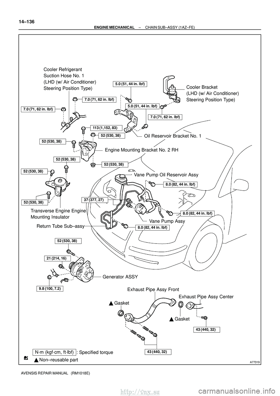
A77319
N´m (kgf´cm, ft´lbf): Specified torque
� Non±reusable part �
Gasket
Cooler Bracket
(LHD (w/ Air Conditioner)
Steering Position Type)
113 (1,152, 83)
Cooler Refrigerant
Suction Hose No. 1
(LHD (w/ Air Conditioner)
Steering Position Type)
8.0 (82, 44 in. �lbf)
8.0 (82, 44 in. �lbf)
8.0 (82, 44 in. �lbf)
52 (530, 38)
Transverse Engine Engine
Mounting Insulator
Vane Pump Oil Reservoir Assy
Return Tube Sub±assy
52 (530, 38)
21 (214, 16)
9.8 (100, 7.2)
Generator ASSY
Exhaust Pipe Assy Front
43 (440, 32)
� Gasket
43 (440, 32)
7.0 (71, 62 in. �lbf)
52 (530, 38)
7.0 (71, 62 in. �lbf)
Oil Reservoir Bracket No. 1
52 (530, 38)
52 (530, 38)
Engine Mounting Bracket No. 2 RH
7.0 (71, 62 in. �lbf)
5.0 (51, 44 in. �lbf)
5.0 (51, 44 in. �lbf)
52 (530, 38)
Exhaust Pipe Assy Center
52 (530, 38)
Vane Pump Assy
37 (377, 27)
14±136
±
ENGINE MECHANICAL CHAIN SUB±ASSY (1AZ±FE)
AVENSIS REPAIR MANUAL (RM1018E)
http://vnx.su
Page 499 of 2234
A77303
A77308
A77306
A77307
14±140
±
ENGINE MECHANICAL CHAIN SUB±ASSY (1AZ±FE)
AVENSIS REPAIR MANUAL (RM1018E)
13. SEPARATE COOLER REFRIGERANT SUCTION HOSE NO.1 (LHD(W/ AIR CONDITIONER) STEERING
POSITION TYPE)
(a) Remove the 2 nuts and separate the suction hose.
14. SEPARATE VANE PUMP OIL RESERVOIR ASSY
NOTICE:
Do not disconnect the 2 hoses. 15. REMOVE OIL RESERVOIR BRACKET NO.1
(a) Remove the 2 bolts and the oil pump reservoir bracket No.1.
16. SEPARATE ENGINE WIRE
(a) Remove the bolt and separate the clamp and engine wire.
17. REMOVE ENGINE SERVICE COVER BRACKET RH (W/O AIR CONDITIONING)
(a) Remove the bolt and the engine service cover bracket RH. 18. REMOVE COOLER BRACKET (LHD(W/ AIRCONDITIONER) STEERING POSITION TYPE)
(a) Remove the bolt and cooler bracket.
http://vnx.su
Page 500 of 2234

14±141
AVENSIS REPAIR MANUAL (RM1018E)")
A77283
A77284
A77285
Unleaded Gasoline
Timing
Marks
�eaded Gasoline
Timing
Marks
Timing
Marks
Timing
Marks
±
ENGINE MECHANICAL CHAIN SUB±ASSY (1AZ±FE)
14±141
AVENSIS REPAIR MANUAL (RM1018E)
19. REMOVE ENGINE SERVICE COVER BRACKET RH (RHD(W/ AIR CONDITIONER) STEERING
POSITION TYPE)
(a) Remove the bolt and the engine service cover bracket RH.
20. REMOVE IGNITION COIL ASSY
(a) Remove the 4 bolts and 4 ignition coils.
21. REMOVE CYLINDER HEAD COVER SUB±ASSY
(a) Disconnect the 2 PCV hoses from the cylinder head cov-er.
(b) Remove the 8 bolts and 2 nuts, and then remove the cylin- der head cover and gasket.
22. SET NO. 1 CYLINDER TO TDC/COMPRESSION
(a) Turn the crankshaft pulley, and align its timing notch with timing mark 0 of the timing chain cover.
(b) Check that the timing marks of the camshaft timing gear are aligned with the timing marks located on the No. 1 and
No. 2 bearing caps as shown in the illustration.
If not, turn the crankshaft 1 revolution (360 �) and align the
marks as above.
http://vnx.su
Page 511 of 2234

AVENSIS REPAIR MANUAL (RM1018E)
(b)Apply seal packing to the 2 locations as shown in the il- lustra")
A77399
Seal Packing
A77400NutNut
A
BC
A A
AAB
14±152
±
ENGINE MECHANICALCHAIN SUB±ASSY(1AZ±FE)
AVENSIS REPAIR MANUAL (RM1018E)
(b)Apply seal packing to the 2 locations as shown in the il- lustration.
Seal Packing: Part No. 08826±00080 or equivalent
NOTICE:
�Remove any oil from the contact surface.
�Install the cylinder head cover within 5 minutes after
applying seal packing.
�Do not expose the seal to engine oil 2 hours after
installing.
(c)install the cylinder head cover with the 8 bolts and 2 nuts. Torque:
Bolt A 11 N�m (112 kgf�cm, 8 ft�lbf)
Bolt B 14 N�m (143 kgf�cm, 10 ft�lbf)
Bolt C 21 N�m (214 kgf�cm, 15 ft�lbf)
Nut 11 N �m (112 kgf�cm, 8 ft �lbf)
55.INSTALL ENGINE SERVICE COVER BRACKET RH (W/O AIR CONDITIONING) Torque: 9.0 N �m (92 kgf�cm,80 in. �lbf)
56.INSTALL COOLER BRACKET (LHD(W/ AIR CONDITIONER) STEERING POSITION TYPE) Torque: 9.0 N �m (92 kgf�cm,80 in. �lbf)
57.INSTALL ENGINE SERVICE COVER BRACKET RH (RHD(W/ AIR CONDITIONER) STEERING
POSITION TYPE)
Torque: 9.0 N �m (92 kgf�cm,80 in. �lbf)
58.INSTALL ENGINE WIRE Torque: 7.0 N �m (71 kgf�cm,62 in. �lbf)
59.INSTALL OIL RESERVOIR BRACKET NO.1 Torque: 8.0 N �m (82 kgf�cm,71 in. �lbf)
60.IN STALL COOL ER REFRIGERANT SUCTION HOSE NO.1 (LHD(W/ AIR CONDITION ER)
STEERING POSITION TYPE)
61.INSTALL RETURN TUBE SUB±ASSY
Torque: 8.0 N �m (82 kgf�cm,71 in. �lbf)
62.INSTALL IGNITION COIL ASSY Torque: 9.0 N �m (92 kgf�cm,80 in. �lbf)
63.INSTALL VANE PUMP ASSY
Torque: 37 N �m (377 kgf�cm,27 ft�lbf)
64.INSTALL EXHAUST PIPE ASSY FRONT (See page 15±7)
65.INSTALL GENERATOR ASSY (See page 19±20)
66.INSTALL FAN AND GENERATOR V BELT (See page 14±105) SST 09249±63010
67. ADD ENGINE OIL
68. CHECK FOR ENGINE OIL LEAKS
69. INSTALL ENGINE COVER SUB±ASSY NO.1 Torque: 7.0 N �m (71 kgf �cm, 62 in. �lbf)
70. INSTALL FRONT WHEEL RH Torque: 103 N� m (1,050 kgf�cm, 76 ft �lbf)
http://vnx.su
Page 513 of 2234
A77303
A77308
A77306
A77307
14±140
±
ENGINE MECHANICAL CHAIN SUB±ASSY (1AZ±FE)
AVENSIS REPAIR MANUAL (RM1018E)
13. SEPARATE COOLER REFRIGERANT SUCTION HOSE NO.1 (LHD(W/ AIR CONDITIONER) STEERING
POSITION TYPE)
(a) Remove the 2 nuts and separate the suction hose.
14. SEPARATE VANE PUMP OIL RESERVOIR ASSY
NOTICE:
Do not disconnect the 2 hoses. 15. REMOVE OIL RESERVOIR BRACKET NO.1
(a) Remove the 2 bolts and the oil pump reservoir bracket No.1.
16. SEPARATE ENGINE WIRE
(a) Remove the bolt and separate the clamp and engine wire.
17. REMOVE ENGINE SERVICE COVER BRACKET RH (W/O AIR CONDITIONING)
(a) Remove the bolt and the engine service cover bracket RH. 18. REMOVE COOLER BRACKET (LHD(W/ AIRCONDITIONER) STEERING POSITION TYPE)
(a) Remove the bolt and cooler bracket.
http://vnx.su
Page 514 of 2234

14±141
AVENSIS REPAIR MANUAL (RM1018E)")
A77283
A77284
A77285
Unleaded Gasoline
Timing
Marks
�eaded Gasoline
Timing
Marks
Timing
Marks
Timing
Marks
±
ENGINE MECHANICAL CHAIN SUB±ASSY (1AZ±FE)
14±141
AVENSIS REPAIR MANUAL (RM1018E)
19. REMOVE ENGINE SERVICE COVER BRACKET RH (RHD(W/ AIR CONDITIONER) STEERING
POSITION TYPE)
(a) Remove the bolt and the engine service cover bracket RH.
20. REMOVE IGNITION COIL ASSY
(a) Remove the 4 bolts and 4 ignition coils.
21. REMOVE CYLINDER HEAD COVER SUB±ASSY
(a) Disconnect the 2 PCV hoses from the cylinder head cov-er.
(b) Remove the 8 bolts and 2 nuts, and then remove the cylin- der head cover and gasket.
22. SET NO. 1 CYLINDER TO TDC/COMPRESSION
(a) Turn the crankshaft pulley, and align its timing notch with timing mark 0 of the timing chain cover.
(b) Check that the timing marks of the camshaft timing gear are aligned with the timing marks located on the No. 1 and
No. 2 bearing caps as shown in the illustration.
If not, turn the crankshaft 1 revolution (360 �) and align the
marks as above.
http://vnx.su

AVENSIS REPAIR MANUAL (RM1018E)
(d)Observe these precautions when connecting the fuel tube connectors (Quick Type):
(1)Check that there is n")

AVENSIS REPAIR MANUAL (RM1018E)
13. SEPARATE COOLER REFRIGERANT SUCTION HOSE NO.1 (LHD(W/ AIR CONDITIONER) STEERING")

AVENSIS REPAIR MANUAL (RM1018E)
13. SEPARATE COOLER REFRIGERANT SUCTION HOSE NO.1 (LHD(W/ AIR CONDITIONER) STEERING")