Page 1777 of 2234
B66968
B62423
1
2
B62422
B61441
±
ENGINE HOOD/DOORFRONT DOOR
75±15
AVENSIS REPAIR MANUAL (RM1018E)
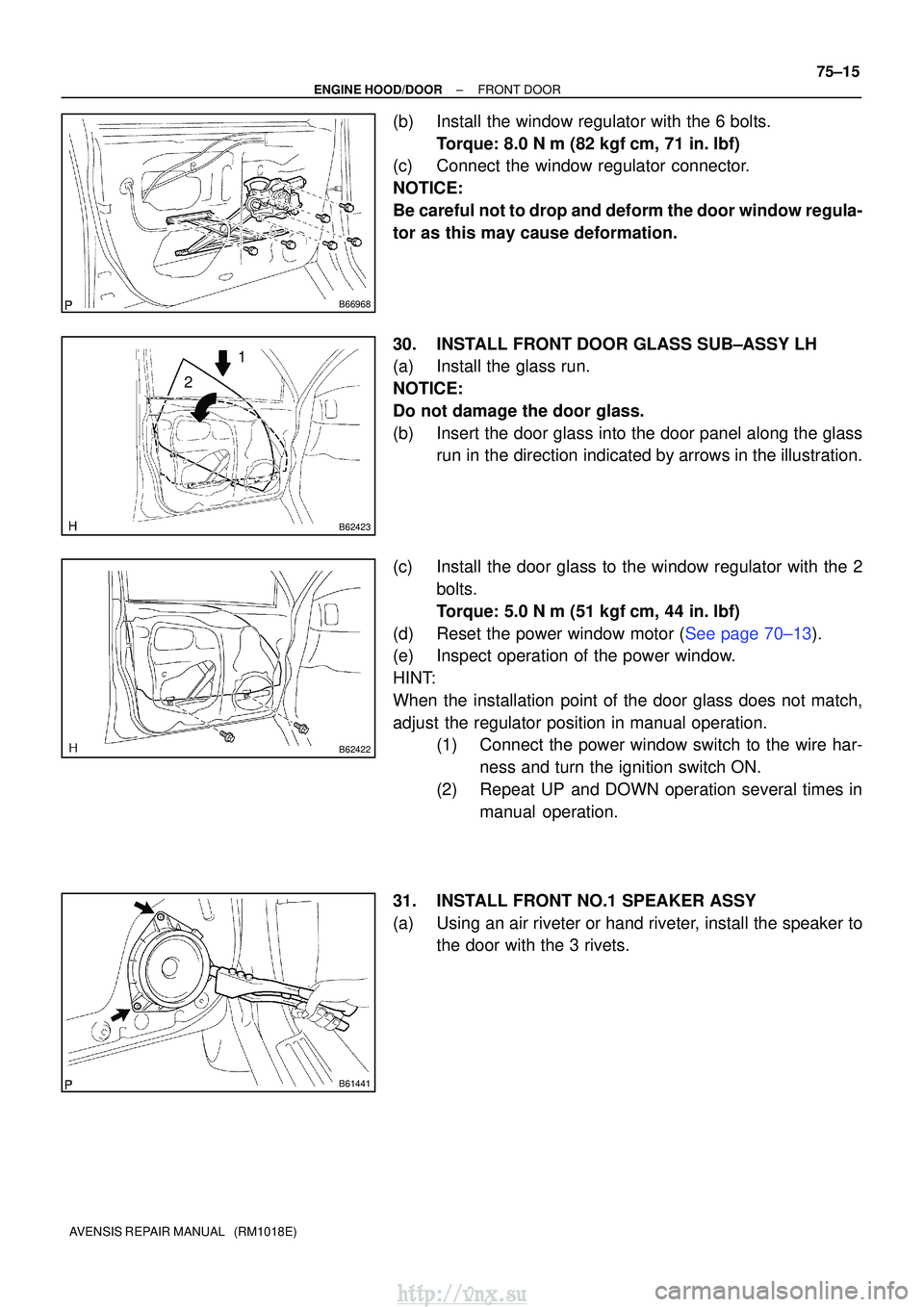
(b)Install the window regulator with the 6 bolts.
Torque: 8.0 N �m (82 kgf�cm, 71 in. �lbf)
(c)Connect the window regulator connector.
NOTICE:
Be careful not to drop and deform the door window regula-
tor as this may cause deformation.
30.INSTALL FRONT DOOR GLASS SUB±ASSY LH
(a)Install the glass run.
NOTICE:
Do not damage the door glass.
(b)Insert the door glass into the door panel along the glass run in the direction indicated by arrows in the illustration.
(c)Install the door glass to the window regulator with the 2 bolts.
Torque: 5.0 N�m (51 kgf �cm, 44 in.�lbf)
(d)Reset the power window motor (See page 70±13).
(e) Inspect operation of the power window.
HINT:
When the installation point of the door glass does not match,
adjust the regulator position in manual operation. (1) Connect the power window switch to the wire har-
ness and turn the ignition switch ON.
(2) Repeat UP and DOWN operation several times in manual operation.
31. INSTALL FRONT NO.1 SPEAKER ASSY
(a) Using an air riveter or hand riveter, install the speaker to the door with the 3 rivets.
http://vnx.su
Page 1815 of 2234
760W7±01
B67608
Tape
Tape
76±24
±
EXTERIOR/INTERIOR TRIMREAR DOOR BELT MOULDING ASSY LH
AVENSIS REPAIR MANUAL (RM1018E)
REAR DOOR BELT MOULDING ASSY LH
REPLACEMENT
HINT:
�The installation is in the reverse order of the removal.
�On the RH side, use the same procedures as on the LH side.
1.REMOVE REAR DOOR WINDOW REGULATOR HANDLE ASSY (See page 75±22)
2.REMOVE REAR DOOR TRIM BASE LH (See page 75±22)
3. REMOVE POWER WINDOW REGULATOR SWITCH ASSY REAR (W/ POWER WINDOW) (See page 75±22)
4.REMOVE REAR DOOR TRIM BOARD SUB±ASSY LH (See page 75±22)
5.REMOVE REAR DOOR GLASS WEATHERSTRIP INNER LH (See page 75±22)
6.REMOVE REAR DOOR SERVICE HOLE COVER LH (See page 75±22)
7. REMOVE REAR DOOR BELT MOULDING ASSY LH
(a) Put protective tape under the moulding.
(b) Using a screwdriver or moulding remover, pry out theclaws and remove the moulding.
HINT:
Tape the screwdriver tip before use.
http://vnx.su
Page 1838 of 2234
760WZ±01
B70684
Front Pillar Garnish RH
Cowl Side Trim
Board RH
Front Door Opening Trim
Weatherstrip RH
Front Door
Scuff Plate RH
Center Pillar Garnish
Lower RH
Center Pillar Garnish
Upper RH
Rear Door
Opening Trim
Weatherstrip RH
Rear Door Scuff Plate RH
Front Door Scuff Plate LH
Rear Door Scuff Plate LH
Cowl Side Trim
Board LHFront Door Opening Trim
Weatherstrip LH
Rear Door
Opening Trim
Weatherstrip LH
Center Pillar Garnish Lower LH
Deck Floor
Box Rear
Tonneau Cover
Assy
Deck Board
Sub±assy
Deck Floor
Box Front
Deck Floor
Box RH
Deck Floor
Box LH
Deck Trim
Side Board RH
Deck Trim Side Board LH
Roof Side
Garnish Inner RH
Roof Side
Garnish Inner LH Rear Window Side
Garnish RH
Rear Window Side
Garnish LH
Center Pillar
Garnish
Upper LH
Front Pillar
Garnish LH
N
�m (kgf� cm ft�lbf): Specified torque
41.2 (420, 30)
41.2 (420, 30)
±
EXTERIOR/INTERIOR TRIM ROOF HEADLINING ASSY (WAGON MODELS)
76±51
AVENSIS REPAIR MANUAL (RM1018E)
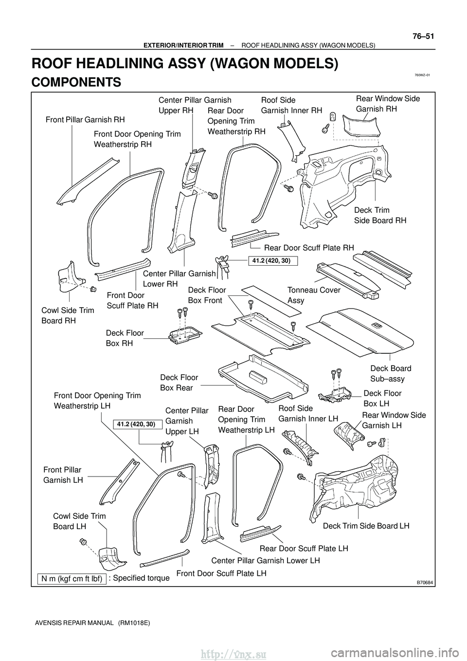
ROOF HEADLINING ASSY (WAGON MODELS)
COMPONENTS
http://vnx.su
Page 1844 of 2234
B66536
Clip
Claw
B66540
Clip
B66538
Clip
B66539
Clip
±
EXTERIOR/INTERIOR TRIM ROOF HEADLINING ASSY (WAGON MODELS)
76±57
AVENSIS REPAIR MANUAL (RM1018E)
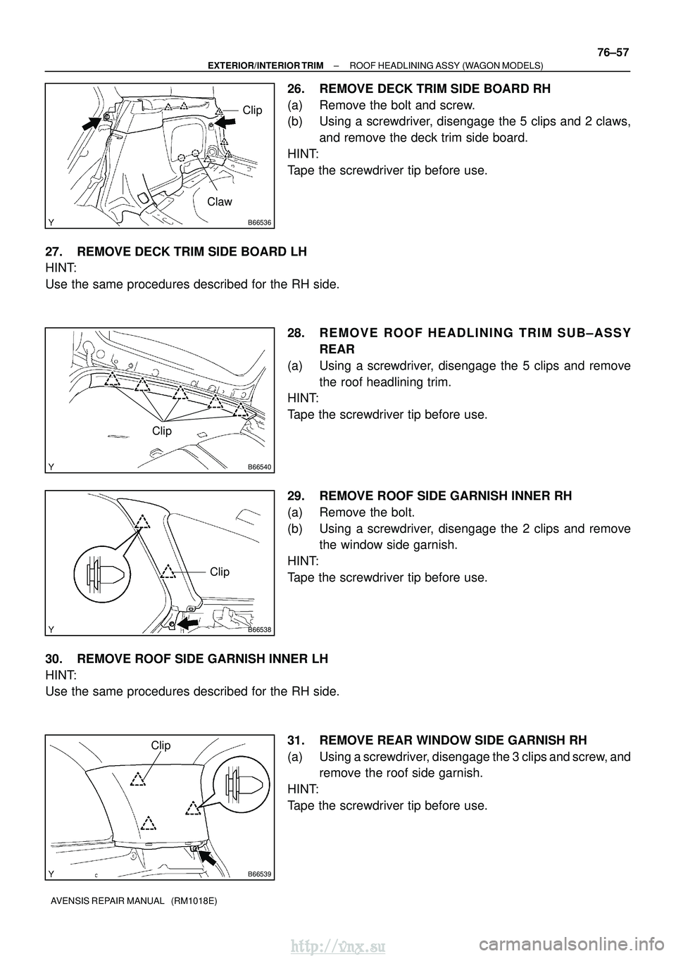
26. REMOVE DECK TRIM SIDE BOARD RH
(a) Remove the bolt and screw.
(b) Using a screwdriver, disengage the 5 clips and 2 claws,
and remove the deck trim side board.
HINT:
Tape the screwdriver tip before use.
27. REMOVE DECK TRIM SIDE BOARD LH
HINT:
Use the same procedures described for the RH side. 28. REMOVE ROOF HEADLINING TRIM SUB±ASSYREAR
(a) Using a screwdriver, disengage the 5 clips and remove the roof headlining trim.
HINT:
Tape the screwdriver tip before use.
29. REMOVE ROOF SIDE GARNISH INNER RH
(a) Remove the bolt.
(b) Using a screwdriver, disengage the 2 clips and remove the window side garnish.
HINT:
Tape the screwdriver tip before use.
30. REMOVE ROOF SIDE GARNISH INNER LH
HINT:
Use the same procedures described for the RH side. 31. REMOVE REAR WINDOW SIDE GARNISH RH
(a) Using a screwdriver, disengage the 3 clips and screw, andremove the roof side garnish.
HINT:
Tape the screwdriver tip before use.
http://vnx.su
Page 1845 of 2234
B66528
Clip
B65292
700 mm120 mm
Adhesive Tape
Adhesive Tape Protective Cover
76±58
±
EXTERIOR/INTERIOR TRIM ROOF HEADLINING ASSY (WAGON MODELS)
AVENSIS REPAIR MANUAL (RM1018E)
32. REMOVE REAR WINDOW SIDE GARNISH LH
HINT:
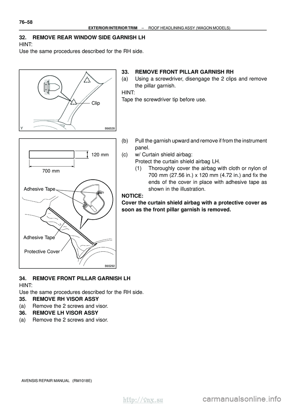
Use the same procedures described for the RH side. 33. REMOVE FRONT PILLAR GARNISH RH
(a) Using a screwdriver, disengage the 2 clips and removethe pillar garnish.
HINT:
Tape the screwdriver tip before use.
(b) Pull the garnish upward and remove if from the instrument panel.
(c) w/ Curtain shield airbag: Protect the curtain shield airbag LH.
(1) Thoroughly cover the airbag with cloth or nylon of700 mm (27.56 in.) x 120 mm (4.72 in.) and fix the
ends of the cover in place with adhesive tape as
shown in the illustration.
NOTICE:
Cover the curtain shield airbag with a protective cover as
soon as the front pillar garnish is removed.
34. REMOVE FRONT PILLAR GARNISH LH
HINT:
Use the same procedures described for the RH side.
35. REMOVE RH VISOR ASSY
(a) Remove the 2 screws and visor.
36. REMOVE LH VISOR ASSY
(a) Remove the 2 screws and visor.
http://vnx.su
Page 1856 of 2234
8AVENSIS (EWD526E)
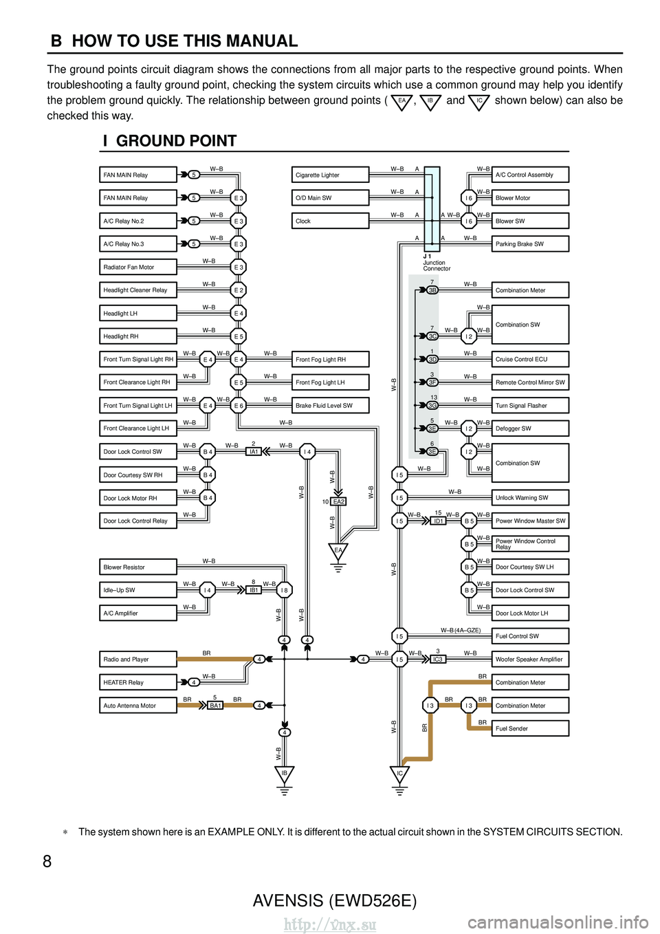
B HOW TO USE THIS MANUAL
The ground points circuit diagram shows the connections from all major p\
arts to the respective ground points. When
troubleshooting a faulty ground point, checking the system circuits which use a common \
ground may help you identify
the problem ground quickly. The relationship between ground points (
EA, IB and IC shown below) can also be
checked this way.
5
5
5
5
44 4
4
4
BA1 5 IB1
8 EA2
ID115
IC3 3
IA1
2
E 3
W–B W–B W–B
W–B
W–B
W–B
W–B
W–B
W–BW –B
W–B
W–BW –B
W–B
W–BW –BW –B
W–B
W–B W–B
W–B
W–B
W–B
W–B
W–BW –BW–B
W–B
BR
W–B
BR BR
W–B W–B
W–B
W–B
W–B
W–B
W–B
W–BW –B
W–B
W–B
W–B
W–B
W–BBR
W–B
BR
BR
BR
W–B (4A–GZE)
W–B
W–B I 2
I 2
B 5
I 5 I 5
I 5
B 5
B 5
B 5
I 5
I 5 I 3
I 3
E 3
E 3
E 3
E 2
E 4
E 5
E 4
E 5
E 6
E 4 E 4
B 4
EA
I 4
B 4
B 4
I 4 I 8
IB IC
4
4 3E
5
3E 6
3G
13
3F
3
3D
1
3B
7 W–B
W–B
W–B
W–B
W–B
W–B
W–B
W–B
W–BW–B
W–B
W–B
W–B
W–B
W–B I 6
I 6
I 2
3C 7
10 A A
A
A
A
A
Junction
Connector J 1
W–B
W–B
W–BW –B
BR
W–B
W–B
W–B
W–B
W–B
W–B
I GROUND POINT
FAN MAIN Relay
FAN MAIN Relay
A/C Relay No.2
A/C Relay No.3
Radiator Fan Motor
Headlight Cleaner Relay
Headlight LH
Headlight RH
Front Fog Light LH
Brake Fluid Level SW Front Fog Light RH
Front Turn Signal Light RH
Front Clearance Light RH
Front Turn Signal Light LH
Front Clearance Light LH
Door Lock Control SW
Door Courtesy SW RH
Door Lock Motor RH
Door Lock Control Relay
Blower Resistor
Idle–Up SW
A/C Amplifier
Radio and Player
HEATER Relay
Auto Antenna Motor A/C Control Assembly
Blower Motor
Blower SW
Parking Brake SW
Combination Meter
Combination SW
Cruise Control ECU
Remote Control Mirror SW
Turn Signal Flasher
Defogger SW
Unlock Warning SW
Power Window Master SW
Power Window Control
Relay
Door Courtesy SW LH
Door Lock Control SW
Door Lock Motor LH
Fuel Control SW
Woofer Speaker Amplifier
Combination Meter
Combination Meter
Fuel Sender
Cigarette Lighter
O/D Main SW
Clock
Combination SW
∗The system shown here is an EXAMPLE ONLY. It is different to the actual circuit shown in the SYSTEM CIRCUITS SECTION.
http://vnx.su
Page 1869 of 2234
![TOYOTA AVENSIS 2003 Service Repair Manual AVENSIS (EWD526E)21
F
[Instrument Panel]
(LHD)
Fuse Block
J/B No.6
Wiper Relay
Door Control
Receiver
Headlight Beam
Level Control
ECU
A/C Control
Assembly
Option Connector
(Navigation ECU)
Engine and TOYOTA AVENSIS 2003 Service Repair Manual AVENSIS (EWD526E)21
F
[Instrument Panel]
(LHD)
Fuse Block
J/B No.6
Wiper Relay
Door Control
Receiver
Headlight Beam
Level Control
ECU
A/C Control
Assembly
Option Connector
(Navigation ECU)
Engine and](/manual-img/14/57444/w960_57444-1868.png)
AVENSIS (EWD526E)21
F
[Instrument Panel]
(LHD)
Fuse Block
J/B No.6
Wiper Relay
Door Control
Receiver
Headlight Beam
Level Control
ECU
A/C Control
Assembly
Option Connector
(Navigation ECU)
Engine and ECT
ECU (A/T)
Engine ECU (M/T)
Navigation ECUShift Lock
Control ECUAirbag Sensor
Assembly
Driver Side
R/B
Rear Window
Defogger Relay
Turn Signal
Flasher Relay
Rear Fog
Light Relay
Circuit Opening
Relay
Integration
Relay
Driver Side J/B EPS ECU
Transponder Key
AmplifierTransponder Key
ComputerAntenna
AmplifierCenter J/B
(RHD)
Shift Lock
Control ECU
Center J/B
Turn Signal
Flasher Relay
Theft Deterrent
ECU
Headlight Beam
Level Control ECU
Wiper Relay
Fuse Block
J/B No.6
Transponder
Key Amplifier
Airbag Sensor
AssemblyOption Connector
(Navigation ECU)
Driver Side
J/B
Integration Relay
Engine and ECT
ECU (A/T)
Engine ECU
(M/T)
Navigation ECU
Circuit Opening
Relay
Rear Fog
Light Relay
A/C Control
Assembly
Door Control
Receiver
Driver Side
R/BAntenna
AmplifierTransponder
Key ComputerEPS ECURear Window
Defogger Relay
http://vnx.su
Page 1880 of 2234
![TOYOTA AVENSIS 2003 Service Repair Manual 38AVENSIS (EWD526E)
G ELECTRICAL WIRING ROUTING
Position of Parts in Engine Compartment
[LHD : 1AZ–FSE]
A5
F6
C6
A10
H2
H6
F11
F9
(*1)
(*2) *1:w/ HID
*2:w/o HID
F10
F2
E4
A6
A4
E5
F5
B1
H1
H5
E2
F7 TOYOTA AVENSIS 2003 Service Repair Manual 38AVENSIS (EWD526E)
G ELECTRICAL WIRING ROUTING
Position of Parts in Engine Compartment
[LHD : 1AZ–FSE]
A5
F6
C6
A10
H2
H6
F11
F9
(*1)
(*2) *1:w/ HID
*2:w/o HID
F10
F2
E4
A6
A4
E5
F5
B1
H1
H5
E2
F7](/manual-img/14/57444/w960_57444-1879.png)
38AVENSIS (EWD526E)
G ELECTRICAL WIRING ROUTING
Position of Parts in Engine Compartment
[LHD : 1AZ–FSE]
A5
F6
C6
A10
H2
H6
F11
F9
(*1)
(*2) *1:w/ HID
*2:w/o HID
F10
F2
E4
A6
A4
E5
F5
B1
H1
H5
E2
F7
F8
H9C2H10F16H7C1H8B3B2F13F12
H12A12A3C3A11H3F4H4H11A1A2E1A9F3F1
C5
(A/T)
(*1)
(*2)
(M/T)
A 1 A/C Ambient Temp. Sensor
A 2 A/C Condenser Fan Motor
A 3 A/C Pressure Sensor
A 4 ABS Speed Sensor Front LH
A 5 ABS Speed Sensor Front RH
A 6 Air Flow Meter
A 9 Airbag Sensor Front LH
A 10 Airbag Sensor Front RH
A 11 Alternator
A 12 Alternator
B 1 Back–Up Light SW
B 2 Brake Booster Pressure Sensor
B 3 Brake Fluid Level Warning SW
C 1 Camshaft Position Sensor
C 2 Camshaft Timing Oil Control Valve
C 3 Compressor Assembly
C 5 Counter Gear Speed Sensor
C 6 Crankshaft Position Sensor
E 1 ECT Solenoid
E 2 EFI Water Temp. Sensor
E 4 Electronic Driver Unit
E 5 Electronic Driver Unit
F 1 Front Clearance Light LH
F 2 Front Clearance Light RH
F 3 Front Fog Light LH F 4 Front Fog Light RH
F 5 Front Side Turn Signal Light LH
F 6 Front Side Turn Signal Light RH
F 7 Front Turn Signal Light LH
Headlight Control ECU LH
F 8 Front Turn Signal Light LH Headlight LH (Low)
F 9 Front Turn Signal Light RH Headlight Control ECU RH
F 10 Front Turn Signal Light RH Headlight RH (Low)
F 11 Front Washer Motor
F 12 Front Window Deicer
F 13 Front Wiper Motor
F 16 Fuel Pressure Sensor
H 1 Headlight Beam Level Control Actuator LH
H 2 Headlight Beam Level Control Actuator RH
H 3 Headlight Cleaner Control Relay
H 4 Headlight Cleaner Motor
H 5 Headlight LH (High)
H 6 Headlight RH (High)
H 7 Heated Oxygen Sensor (Bank 1 Sensor 1)
H 8 Heated Oxygen Sensor (Bank 1 Sensor 2)
H 9 Heated Oxygen Sensor (Bank 2 Sensor 1)
H 10 Heated Oxygen Sensor (Bank 2 Sensor 2)
H 11 Horn LH
H 12 Horn RH
http://vnx.su