Page 1647 of 2234
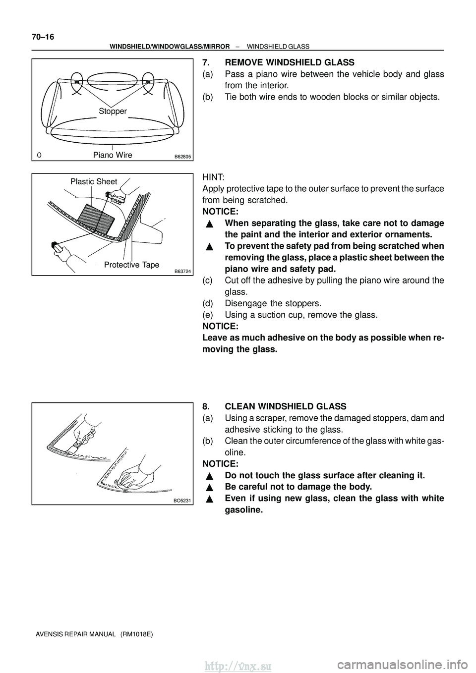
B62805
Stopper
Piano Wire
B63724Protective Tape
Plastic Sheet
BO5231
70±16
±
WINDSHIELD/WINDOWGLASS/MIRROR WINDSHIELD GLASS
AVENSIS REPAIR MANUAL (RM1018E)
7. REMOVE WINDSHIELD GLASS
(a) Pass a piano wire between the vehicle body and glass from the interior.
(b) Tie both wire ends to wooden blocks or similar objects.
HINT:
Apply protective tape to the outer surface to prevent the surface
from being scratched.
NOTICE:
�When separating the glass, take care not to damage
the paint and the interior and exterior ornaments.
�To prevent the safety pad from being scratched when
removing the glass, place a plastic sheet between the
piano wire and safety pad.
(c) Cut off the adhesive by pulling the piano wire around the
glass.
(d) Disengage the stoppers.
(e) Using a suction cup, remove the glass.
NOTICE:
Leave as much adhesive on the body as possible when re-
moving the glass.
8. CLEAN WINDSHIELD GLASS
(a) Using a scraper, remove the damaged stoppers, dam and adhesive sticking to the glass.
(b) Clean the outer circumference of the glass with white gas-
oline.
NOTICE:
�Do not touch the glass surface after cleaning it.
�Be careful not to damage the body.
�Even if using new glass, clean the glass with white
gasoline.
http://vnx.su
Page 1648 of 2234
B62806
B
AA Ceramic Notch
Backside
B63758
±
WINDSHIELD/WINDOWGLASS/MIRROR WINDSHIELD GLASS
70±17
AVENSIS REPAIR MANUAL (RM1018E)
9. INSTALL WINDSHIELD GLASS STOPPER NO.2
(a) Coat the installation part of the stopper with Primer G.
NOTICE:
�Allow the primer coating to dry for 3 minutes or more.
�Do not keep any of the opened Primer G for later use.
�Do not apply too much primer.
(b) Install 2 new stoppers onto the glass, as shown in the il-
lustration.
Standard dimension:
A40.0 mm (1.575 in.)
B7.7 mm (0.303 in.)
10. INSTALL WINDSHIELD GLASS STOPPER NO.1
(a) Install 2 new stoppers to the vehicle body, as shown in theillustration.
http://vnx.su
Page 1649 of 2234
B67032
AA
B
A A B
AA ± A
B ± B
Ceramic Notch Stopper
Dam
DamCeramic Notch
a
C C
C ± C b
Ceramic End
Ceramic End
70±18
±
WINDSHIELD/WINDOWGLASS/MIRROR WINDSHIELD GLASS
AVENSIS REPAIR MANUAL (RM1018E)
11. INSTALL WINDOW GLASS ADHESIVE DAM
(a) Coat the installation part of the window glass adhesive dam with Primer \
G.
NOTICE:
�Allow the primer coating to dry for 3 minutes or more.
�Do not apply too much primer.
(b) Install a new dam, applying double±sided tape all the way around the glass e\
xcept where the dam is installed, as shown in the illustration.
Standard dimension:
a7.0 mm (0.276 in.)
b56.0 mm (2.205 in.)
12. INSTALL WINDSHIELD MOULDING OUTER UPPER
(a) Using a brush or sponge, coat the edge of the glass and the contact surf\
ace with Primer G.
NOTICE:
�Allow the primer coating to dry for 3 minutes or more.
�Do not coat the adhesive with Primer G.
�Do not keep any of the opened Primer G for later use.
(b) Install the moulding.
http://vnx.su
Page 1650 of 2234
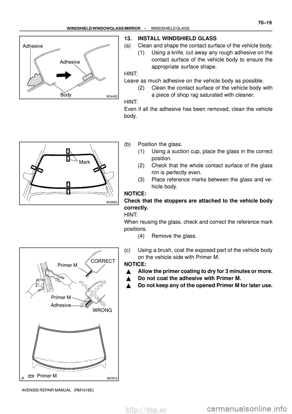
Adhesive
Adhesive
BO4420Body
BO2820
Mark
B67819
Primer M
Primer M
AdhesiveCORRECT
WRONG
Primer M
±
WINDSHIELD/WINDOWGLASS/MIRROR WINDSHIELD GLASS
70±19
AVENSIS REPAIR MANUAL (RM1018E)
13. INSTALL WINDSHIELD GLASS
(a) Clean and shape the contact surface of the vehicle body.
(1) Using a knife, cut away any rough adhesive on the
contact surface of the vehicle body to ensure the
appropriate surface shape.
HINT:
Leave as much adhesive on the vehicle body as possible. (2) Clean the contact surface of the vehicle body witha piece of shop rag saturated with cleaner.
HINT:
Even if all the adhesive has been removed, clean the vehicle
body.
(b) Position the glass. (1) Using a suction cup, place the glass in the correctposition.
(2) Check that the whole contact surface of the glass rim is perfectly even.
(3) Place reference marks between the glass and ve- hicle body.
NOTICE:
Check that the stoppers are attached to the vehicle body
correctly.
HINT:
When reusing the glass, check and correct the reference mark
positions. (4) Remove the glass.
(c) Using a brush, coat the exposed part of the vehicle body on the vehicle side with Primer M.
NOTICE:
�Allow the primer coating to dry for 3 minutes or more.
�Do not coat the adhesive with Primer M.
�Do not keep any of the opened Primer M for later use.
http://vnx.su
Page 1651 of 2234
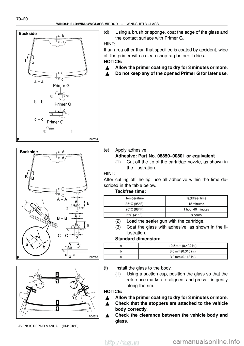
B67034
Primer Ga
a
b
a ± a
c ± c
c
b
b ± b c
Backside
Primer GPrimer G
B67035
A
B aa
b
b
A ± A
C ± C
B ± B
B
A
C
Backside
ba
c
C
c
a b
BO2821
70±20
±
WINDSHIELD/WINDOWGLASS/MIRROR WINDSHIELD GLASS
AVENSIS REPAIR MANUAL (RM1018E)
(d) Using a brush or sponge, coat the edge of the glass and the contact surface with Primer G.
HINT:
If an area other than that specified is coated by accident, wipe
off the primer with a clean shop rag before it dries.
NOTICE:
�Allow the primer coating to dry for 3 minutes or more.
�Do not keep any of the opened Primer G for later use.
(e) Apply adhesive. Adhesive: Part No. 08850±00801 or equivalent
(1) Cut off the tip of the cartridge nozzle, as shown inthe illustration.
HINT:
After cutting off the tip, use all adhesive within the time de-
scribed in the table below.
Tackfree time:
TemperatureTackfree Time
35�C (95� F)15 minutes
20�C (68� F)1 hour 40 minutes
5�C (41� F)8 hours
(2) Load the sealer gun with the cartridge.
(3) Coat the glass with adhesive, as shown in the il-
lustration.
Standard dimension:
a12.5 mm (0.492 in.)
b8.0 mm (0.315 in.)
c3.0 mm (0.118 in.)
(f) Install the glass to the body. (1) Using a suction cup, position the glass so that thereference marks are aligned, and press it in gently
along the rim.
NOTICE:
�Allow the primer coating to dry for 3 minutes or more.
�Check that the stoppers are attached to the vehicle
body correctly.
�Check the clearance between the vehicle body and
glass.
http://vnx.su
Page 1652 of 2234
BO3986
Adhesive
N08495
Adhesive
WindshieldDam
±
WINDSHIELD/WINDOWGLASS/MIRROR WINDSHIELD GLASS
70±21
AVENSIS REPAIR MANUAL (RM1018E)
(2) Lightly press the front surface of the glass to ensure
a close fit.
(3) Using a scraper, remove any excess or protruding adhesive.
HINT:
Apply adhesive onto the glass rim.
NOTICE:
Take care not to drive the vehicle for the time described in
the table below. Minimum time:
TemperatureMinimum time prior to driving vehicle
35�C (95� F)1 hour 30 minutes
20�C (68� F)5 hours
5�C (41� F)24 hours
14. INSPECT FOR LEAKS AND REPAIR
(a) Conduct a leak test after the adhesive has completely hardened.
(b) Seal any leaks with auto glass sealer.
http://vnx.su
Page 1710 of 2234
73±2
±
THEFT DETERRENT & DOOR LOCK POWER DOOR LOCK CONTROL SYSTEM
AVENSIS REPAIR MANUAL (RM1018E)
(d) Check the illumination function. (1) Set the room light switch in the DOOR position.
(2) With all doors locked, check that all doors unlock when the driver side door\
lock cylinder is turnedto UNLOCK using the key and that the room right turns on.
(3) Check that the room light turns off in approx. 15 seconds after the doors have not been opened for a while.
3. w/ Double lock:
CHECK DOUBLE LOCKING FUNCTION SYSTEM
(a) Check that the double locking system is set to ON. (1) Open all the windows.
(2) Turn the ignition switch to LOCK and remove the key.
(3) Open and close the driver side door, and make sure that all doors including the back door areclosed securely.
(4) Push the LOCK switch on the wireless transmitter twice within 5 seconds, and check that the hazard warning lights flash once at this time to show that the system is set.
(5) Try to unlock all doors using the inside handle of the vehicle, and check\
that none of the doors
unlock.
NOTICE:
�The double locking system cannot be set to ON without using the wireless\
transmitter.
�The double locking system operation is not related to the back door.
(b) Check that the double locking system is set to OFF. (1) Push the UNLOCK switch on the wireless transmitter while the double locking system is ON, andcheck that the hazard warning lights flash twice at this time to show th\
at the system is set to OFF.
(2) Check that the doors can be opened both by the inside handle and the outside \
handle.
NOTICE:
If the battery of the wireless transmitter is dead, only the driver side\
door can be opened using the
key. However, the theft deterrent system still remains on. Therefore, be aware that\
the theft alarm
is set off when the door is opened without the use of the wireless trans\
mitter.
http://vnx.su
Page 1720 of 2234
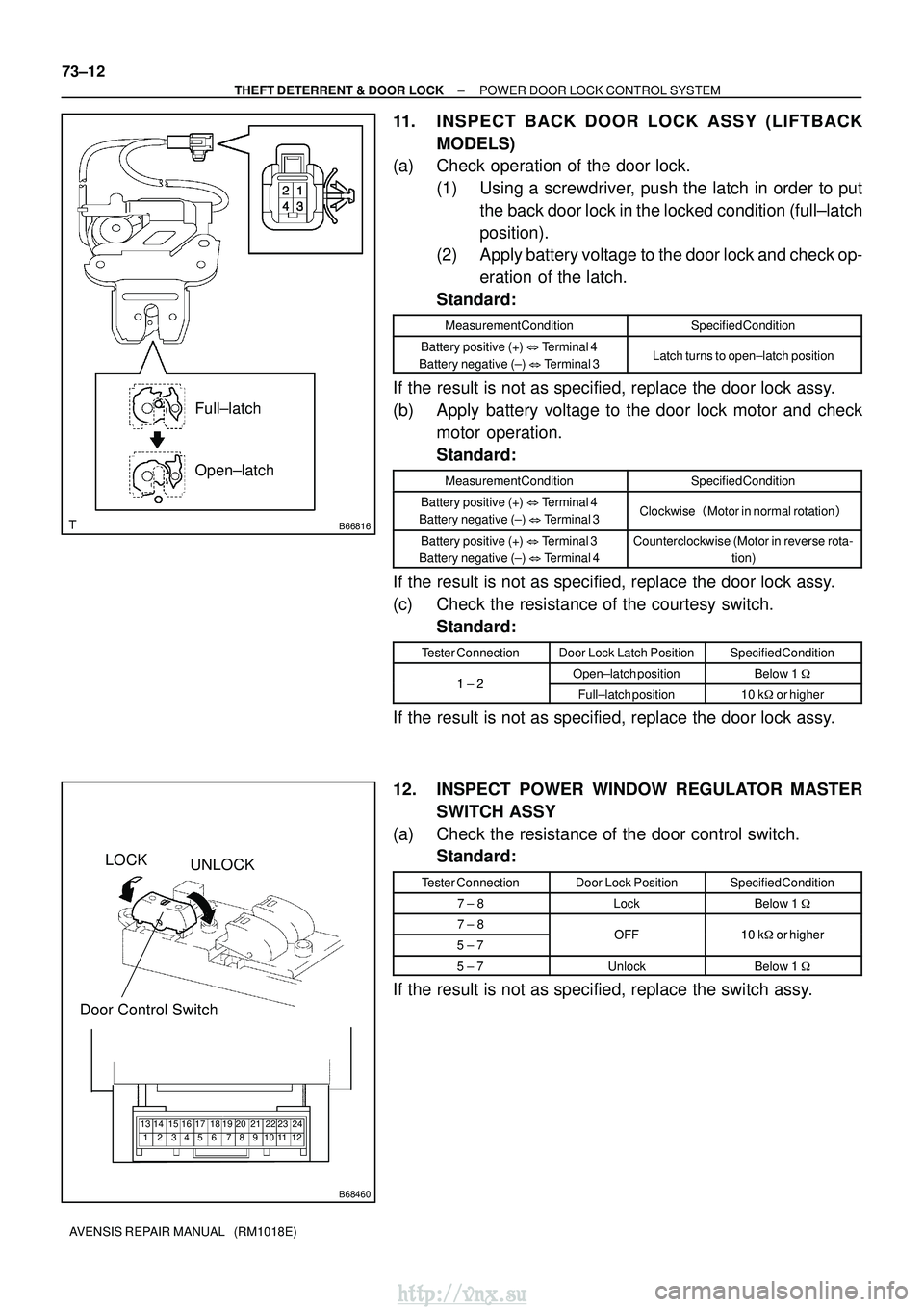
B66816
Full±latch
Open±latch
B68460
LOCKUNLOCK
Door Control Switch
123 6 7 45 8918 19 22 23
20 21 24
10 11
14 15
12
13 16 17
73±12
±
THEFT DETERRENT & DOOR LOCK POWER DOOR LOCK CONTROL SYSTEM
AVENSIS REPAIR MANUAL (RM1018E)
11. INSPECT BACK DOOR LOCK ASSY (LIFT BACK
MODELS)
(a) Check operation of the door lock.
(1) Using a screwdriver, push the latch in order to putthe back door lock in the locked condition (full±latch
position).
(2) Apply battery voltage to the door lock and check op-
eration of the latch.
Standard:
Measurement ConditionSpecified Condition
Battery positive (+) � Terminal 4
Battery negative (±) � Terminal 3Latch turns to open±latch position
If the result is not as specified, replace the door lock assy.
(b) Apply battery voltage to the door lock motor and check
motor operation.
Standard:
Measurement ConditionSpecified Condition
Battery positive (+) � Terminal 4
Battery negative (±) � Terminal 3Clockwise �Motor in normal rotation �
Battery positive (+) � Terminal 3
Battery negative (±) � Terminal 4Counterclockwise (Motor in reverse rota-
tion)
If the result is not as specified, replace the door lock assy.
(c) Check the resistance of the courtesy switch.Standard:
Tester ConnectionDoor Lock Latch PositionSpecified Condition
12Open±latch positionBelow 1 �1 ± 2Full±latch position10 k�or higher
If the result is not as specified, replace the door lock assy.
12. INSPECT POWER WINDOW REGULATOR MASTER
SWITCH ASSY
(a) Check the resistance of the door control switch. Standard:
Tester ConnectionDoor Lock PositionSpecified Condition
7 ± 8LockBelow 1 �
7 ± 8OFF10 k�or higher5 ± 7OFF10 k�or higher
5 ± 7UnlockBelow 1 �
If the result is not as specified, replace the switch assy.
http://vnx.su