Page 121 of 2234

Recomended Tools
09011±12301Socket Wrench 30 mmENGINE REAR OIL SEAL(1CD±FTV)
PARTIAL ENGINE ASSY(1CD±FTV)
PARTIAL ENGINE
AS")
±
PREPARATION ENGINE MECHANICAL
02±15
AVENSIS REPAIR MANUAL (RM1018E)
Recomended Tools
09011±12301Socket Wrench 30 mmENGINE REAR OIL SEAL(1CD±FTV)
PARTIAL ENGINE ASSY(1CD±FTV)
PARTIAL ENGINE
ASSY(1ZZ±FE/3ZZ±FE)
ENGINE REAR OIL
SEAL(1ZZ±FE/3ZZ±FE)
09017±38120Deep Socket Wrench 12 mmPARTIAL ENGINE ASSY(1CD±FTV)
09040±00011Hexagon Wrench SetPARTIAL ENGINE
ASSY(1ZZ±FE/3ZZ±FE)
(09043±20050)Socket Hexagon Wrench 5PARTIAL ENGINE
ASSY(1ZZ±FE/3ZZ±FE)
(09043±20100)Socket Hexagon Wrench 10PARTIAL ENGINE
ASSY(1ZZ±FE/3ZZ±FE)
09043±50100Bi±hexagon Wrench 10 mmCYLINDER HEAD GASKET(1AZ±FE)
CYLINDER HEAD
GASKET(1AZ±FSE)
09090±04020Engine Sling DevicePARTIAL ENGINE ASSY(1CD±FTV)
PARTIAL ENGINE
ASSY(1ZZ±FE/3ZZ±FE)
09216±00021Belt Tension GaugeENGINE(1CD±FTV)
DRIVE BELT(1CD±FTV)
TIMING BELT(1CD±FTV)
CAMSHAFT(1CD±FTV)
CYLINDER HEAD
GASKET(1CD±FTV)
CRANKSHAFT SEAL(1CD±FTV)
(09857±00031)Spark Plug Gap GaugeENGINE(1AZ±FE)
ENGINE(1AZ±FSE)
ENGINE(1ZZ±FE/3ZZ±FE)
Equipment
Hexagon wrench (6mm)
Feeler gauge
CO/HC meter
Compression gauge
Dial indicator
Dial indicator or dial indicator with magnetic base
Micro meter
Radiator cap tester
Straight edge
Tachometer
Torque wrench
http://vnx.su
Page 122 of 2234

Vernier calipers
Tire pressure gauge
Alignment tester
Toe±in gauge
OBD II scan tool
Deep socket wrench 24 mm
Slide calipers
S")
02±16
±
PREPARATION ENGINE MECHANICAL
AVENSIS REPAIR MANUAL (RM1018E)
Vernier calipers
Tire pressure gauge
Alignment tester
Toe±in gauge
OBD II scan tool
Deep socket wrench 24 mm
Slide calipers
Sand paper (#400)
Wooden block
Chain block
Spark plug cleaner
Angle gauge
Universal engine lifter
SSM
08826±00080Seal Packing Black or equivalent
(FIPG)VALVE CLEARANCE(1AZ±FE)
CYLINDER HEAD GASKET(1AZ±FE)
VALVE CLEARANCE(1AZ±FSE)
CYLINDER HEAD
GASKET(1AZ±FSE)
VALVE CLEARANCE(1CD±FTV)
TIMING BELT(1CD±FTV)
CAMSHAFT(1CD±FTV)
CYLINDER HEAD
GASKET(1CD±FTV)
CRANKSHAFT SEAL(1CD±FTV)
PARTIAL ENGINE ASSY(1CD±FTV)
VA LV E
CLEARANCE(1ZZ±FE/3ZZ±FE)
CHAIN
SUB±ASSY(1ZZ±FE/3ZZ±FE)
CAMSHAFT(1ZZ±FE/3ZZ±FE)
CYLINDER HEAD
GASKET(1ZZ±FE/3ZZ±FE)
08833±00070ºAdhesive 1324,º
THREE BOND 1324 or equivalentPARTIAL ENGINE ASSY(1AZ±FE)
ENGINE REAR OIL SEAL(1AZ±FE)
PARTIAL ENGINE ASSY(1AZ±FSE)
ENGINE REAR OIL SEAL(1AZ±FSE)
ENGINE REAR OIL SEAL(1CD±FTV)
PARTIAL ENGINE ASSY(1CD±FTV)
PARTIAL ENGINE
ASSY(1ZZ±FE/3ZZ±FE)
ENGINE REAR OIL
SEAL(1ZZ±FE/3ZZ±FE)
http://vnx.su
Page 134 of 2234
022J8±01
±
PREPARATION IGNITION
02±23
AVENSIS REPAIR MANUAL (RM1018E)
IGNITION
PREPARATION
SST
09249±63010Torque Wrench AdaptorCRANKSHAFT POSITION SENSOR
(1AZ±FE/1AZ±FSE)
Recomended Tools
09082±00040TOYOTA Electrical TesterIGNITION SYSTEM(1AZ±FE)
IGNITION SYSTEM(1AZ±FSE)
IGNITION SYSTEM
(1ZZ±FE/3ZZ±FE)
(09083±00150)Test Lead SetIGNITION SYSTEM(1AZ±FE)
IGNITION SYSTEM(1AZ±FSE)
IGNITION SYSTEM
(1ZZ±FE/3ZZ±FE)
09200±00010Engine Adjust KitIGNITION SYSTEM(1AZ±FE)
IGNITION SYSTEM(1AZ±FSE)
IGNITION SYSTEM
(1ZZ±FE/3ZZ±FE)
(09857±00031)Spark Plug Gap GaugeIGNITION SYSTEM(1AZ±FE)
IGNITION SYSTEM(1AZ±FSE)
IGNITION SYSTEM
(1ZZ±FE/3ZZ±FE)
Equipment
Ohmmeter
Service Wire Harness
Torque wrench
http://vnx.su
Page 201 of 2234

IGNITION
SERVICE DATA
1ZZ±FE/3ZZ±FE:
Spark plug
Recommended spark plug DENSO made NGK made
Electrode gap K16R±U")
031E4±01
03±30
±
SERVICE SPECIFICATIONS IGNITION
AVENSIS REPAIR MANUAL (RM1018E)
IGNITION
SERVICE DATA
1ZZ±FE/3ZZ±FE:
Spark plug
Recommended spark plug DENSO made NGK made
Electrode gap K16R±U11, BKR5EYA11
K16R±U11
BKR5EYA11
1.0 to 1.1 mm (0.039 to 0.043 in.)
Camshaft position sensor
Resistance Cold Hot
835 to 1,400 �
1,060 to 1,645 �
Crankshaft position sensor
Resistance ColdHot
1,630 to 2,740 �
2,065 to 3,225 �
1AZ±FE:
Spark plug
Recommended spark plug DENSO madeNGK made
Electrode gap K20R±U11, BKR6EYA11
K20R±U11
BKR6EYA11
1.0 to 1.1 mm (0.039 to 0.043 in.)
Camshaft position sensor
Resistance Cold Hot
835 to 1,400 �
1,060 to 1,645 �
Crankshaft position sensor
Resistance ColdHot
985 to 1,600 �
1,265 to 1,890 �
1AZ±FSE:
Spark plug
Recommended spark plug DENSO made
Electrode gap SK20BR11
SK20BR11
1.0 to 1.1 mm (0.039 to 0.043 in.)
Camshaft position sensor
Resistance ColdHot
835 to 1,400 �
1,060 to 1,645 �
Crankshaft position sensor
Resistance ColdHot
985 to 1,600 �
1,265 to 1,890 �
http://vnx.su
Page 202 of 2234
031E5±01
±
SERVICE SPECIFICATIONS IGNITION
03±31
AVENSIS REPAIR MANUAL (RM1018E)
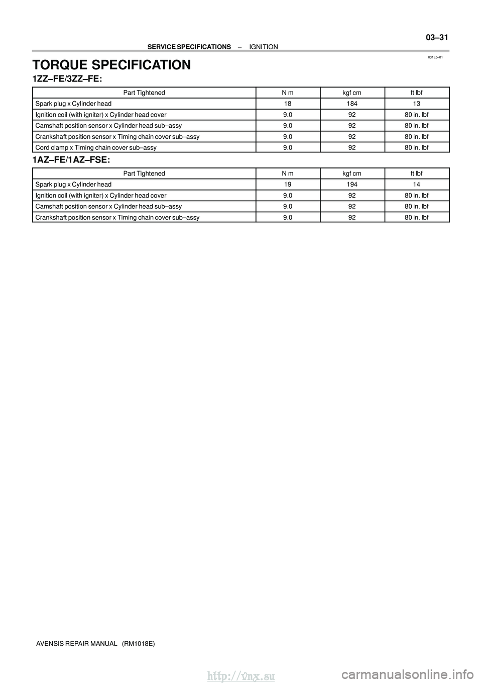
TORQUE SPECIFICATION
1ZZ±FE/3ZZ±FE:
Part TightenedN�mkgf �cmft �lbf
Spark plug x Cylinder head1818413
Ignition coil (with igniter) x Cylinder head cover9.09280 in.� lbf
Camshaft position sensor x Cylinder head sub±assy9.09280 in.�lbf
Crankshaft position sensor x Timing chain cover sub±assy9.09280 in.�lbf
Cord clamp x Timing chain cover sub±assy9.09280 in.�lbf
1AZ±FE/1AZ±FSE:
Part TightenedN�mkgf �cmft �lbf
Spark plug x Cylinder head1919414
Ignition coil (with igniter) x Cylinder head cover9.09280 in.� lbf
Camshaft position sensor x Cylinder head sub±assy9.09280 in.�lbf
Crankshaft position sensor x Timing chain cover sub±assy9.09280 in.�lbf
http://vnx.su
Page 598 of 2234

14±101
AVENSIS REPAIR MANUAL (RM1018E)
ENGINE(1AZ±FE)
INSPECTION
1.INSPECT COOLANT (See page 16±13)
2.INSPECT ENGINE OIL (See page")
140D1±02
CG
TCA51075
A52004
±
ENGINE MECHANICALENGINE(1AZ±FE)
14±101
AVENSIS REPAIR MANUAL (RM1018E)
ENGINE(1AZ±FE)
INSPECTION
1.INSPECT COOLANT (See page 16±13)
2.INSPECT ENGINE OIL (See page 17±6)
3. INSPECT BATTERY
Standard specific gravity: 1.25 to 1.29 at 20� C (68�F)
4. INSPECT AIR CLEANER FILTER ELEMENT SUB±ASSY
5.INSPECT SPARK PLUG (See page 18±9)
6. INSPECT V±RIBBED BELT
7. INSPECT IGNITION TIMING
(a) Warm up engine.
(b) When using hand±held tester:(1) Connect the hand±held tester to the DLC3.
(2) Enter DATA LIST MODE on the hand±held tester.
Ignition timing: 8 to 12 � BTDC
HINT:
Please refer to the hand±held tester operator's manual if you
need help to select DATA LIST.
(c) When not using hand±held tester:
(1) Using SST, connect terminals 13 (TC) and 4 (CG)of DLC3.
SST 09843±18040
NOTICE:
�Make sure of the terminal numbers before connecting
them. Connection with a wrong terminal can damage
the engine.
�Turn OFF all electrical systems before connecting the
terminals.
�Operate the inspection after the cooling fan motor is
turned OFF.
(2) Remove the cylinder head cover No.2.
(3) Pull out the wire harness as shown in the illustration.
Connect the clip of the timing light to the engine.
NOTICE:
�Use a timing light which detects the first signal.
�After checking, be sure to wrap the wire harness with
tape.
(4) Inspect ignition timing at idle.
Ignition timing: 8 to 12 � BTDC
NOTICE:
When checking the ignition timing, shift the transmission
to the neutral position.
HINT:
Run the engine at 1,000 to 1,300 rpm for 5 seconds, check that
the engine rpm returns to the idle speed.
http://vnx.su
Page 599 of 2234

AVENSIS REPAIR MANUAL (RM1018E)
(5) Disconnect terminals 13 (TC) and 4 (CG) of DLC3.
(6) Inspect ignition timing at idle.
Ignition t")
TA C
A52006
A13304
14±102
±
ENGINE MECHANICAL ENGINE (1AZ±FE)
AVENSIS REPAIR MANUAL (RM1018E)
(5) Disconnect terminals 13 (TC) and 4 (CG) of DLC3.
(6) Inspect ignition timing at idle.
Ignition timing: 5 to 15 � BTDC
(7) Confirm that ignition timing to go advanced angle side when the engine rpm is increased.
(8) Remove the timing light.
8. INSPECT ENGINE IDLE SPEED
(a) Warm up engine.
(b) When using hand±held tester:
(1) Connect the hand±held tester to the DLC3.
Idle speed: 650 to 750 rpm
NOTICE:
�Check the idle speed with the cooling fan OFF.
�Switch off all accessories and air conditioning before
connecting the test prove to the terminal.
HINT:
Please refer to the hand±held tester operator's manual if you
need help to select DATA LIST.
(c) When not using hand±held tester.
(1) Using SST, connect the tachometer test prove toterminal 9 (TAC) of DLC3.
SST 09843±18040
(2) Check the idle speed.
Idle speed: 650 to 750 rpm
9. INSPECT COMPRESSION
(a) Warm up and stop the engine.
(b) Disconnect the injector connectors.
(c) Remove the ignition coil.
(d) Remove the spark plugs.
(e) Inspect cylinder compression pressure. SST 09992±00500
(1) Insert a compression gauge into the spark plughole.
(2) Fully open the throttle.
http://vnx.su
Page 600 of 2234

14±103
AVENSIS REPAIR MANUAL (RM1018E)
(3)While cranking the engine, measure the compres-
sion pressure.
Compression pressure:
1,300 kPa (13.3 kgf/cm
2, 189 psi)")
±
ENGINE MECHANICALENGINE(1AZ±FE)
14±103
AVENSIS REPAIR MANUAL (RM1018E)
(3)While cranking the engine, measure the compres-
sion pressure.
Compression pressure:
1,300 kPa (13.3 kgf/cm
2, 189 psi)
Minimum pressure:
1000 kPa (10.2 kgf/cm
2, 145 psi)
Difference between each cylinder:
100 kPa (1.0 kgf/cm
2, 14 psi)
NOTICE:
�Always use a fully charged battery to obtain engine
speed of 250 rpm or more.
�Check other cylinder's compression pressure in the
same way.
�This measurement must be done in as short a time as
possible.
(4)If the cylinder compression is low, pour a small amount of engine oil into the cylinder through the
spark plug hole and inspect again.
HINT:
�If adding oil increases the compression, the piston rings
and/or cylinder bore may be worn or damaged.
�If pressure stays low, a valve may be sticking or seating
improperly, or there may be leakage past the gasket.
10.INSPECT CO/HC
(a)Start the engine.
(b)Run the engine at 2,500 rpm for approximately 180 seconds.
(c)Insert CO/HC meter testing probe at least 40 cm (1.3 ft) into the tail\
pipe during idling.
(d)Check CO/HC concentration at idle. Idle CO concentration: 0 to 0.5 %
Idle HC concentration: Applicable local regulation
(e)If the CO/HC concentration does not conform to specifications, perform troubleshooting in the order given below.
(1)Check heated oxygen sensor operation. (See page 12±6)
(2) See the table below for possible causes, and then inspect and repair the applicable causes ifnecessary.
http://vnx.su

IGNITION
PREPARATION
SST
09249±63010Torque Wrench AdaptorCRANKSHAFT POSITION SENSOR
(1AZ±FE/1AZ±FSE)
Recomended Tools
090")