2003 SSANGYONG MUSSO glove box
[x] Cancel search: glove boxPage 13 of 1574

GENERAL INFORMATION 0B-13
Weather-Strip Lubrication Apply a thin film silicone grease using a clean cloth. EACH TIME THE OIL IS CHANGED Brake System Inspection This inspection should be done when the wheels are removed for rotation. Inspect the lines and the hoses for proper hookup, binding, leaks, cracks, chafing, etc.
Inspect the disc brake pads for wear. Inspect the rotors for surface condition. Inspect other brake parts, theparking brake, etc., at the same time. Inspect the brakes more often if habit or conditions result in frequent braking. Steering, Suspension and Front Drive Axle Boot And Seal Inspection Inspect the front and rear suspension and the steering system for damaged, loose or missing parts, signs of wear or lack of lubrication. Inspect the power steering line and the hoses for proper hookup, binding, leaks, cracks, chafing, etc. Clean and inspect the drive axle boot and seals for damage, tears or leakage. Replace
the seals if necessary. Exhaust System Inspection Inspect the complete system (including the catalytic converter if equipped). Inspect the body near the exhaustsystem. Look for broken, damaged, missing, or out-of- position parts as well as open seams, holes, loose connections, or other conditions which could cause heat buildup in the floor pan or could let exhaust fumes seep into the trunk or passenger compartment. Throttle Linkage Inspection Inspect the throttle linkage for interference or binding, damaged, or missing parts. Lubricate all linkage joints and throttle cable joints, the intermediate throttle shaft
bearing, the return spring at throttle valve assembly, and the accelerator pedal sliding face with suitable grease. Check the throttle cable for free movements. Engine Drive Belts Inspect all belts for cracks, fraying, wear and proper tension. Adjust or replace the belts as needed. Hood Latch Operation When opening the hood, note the operation of the secondary latch. It should keep the hood from opening all the way when the primary latch is released. The hood
must close firmly. AT LEAST ANNUALLY Lap and Shoulder Belts Condition and Operation Inspect the belt system including: the webbing, the
buckles, the latch plates, the retractor, the guide loops and the anchors. Movable Head Restraint Operation On vehicles with movable head restraints, the restraints must stay in the desired position. Spare Tire and Jack Storage Be alert to rattles in the rear of the vehicle. The spare tire, all the jacking equipment, and the tools must besecurely stowed at all times. Oil the jack ratchet or the screw mechanism after each use. Key Lock Service
Lubricate the key lock cylinder. Body Lubrication Service Lubricate all the body door hinges including the hood,
the fuel door, the rear compartment hinges and the latches, the glove box and the console doors, and anyfolding seat hardware. Underbody Flushing Flushing the underbody will remove any corrosive materials used for ice and snow removal and dust control.
At least every spring clean the underbody. First, loosen the sediment packed in closed areas of the vehicle. Then
flush the underbody with plain water. Engine Cooling System Inspect the coolant and freeze protection fluid. If the fluid
is dirty or rusty, drain, flush and refill the engine cooling system with new coolant. Keep the coolant at the propermixture in order to ensure proper freeze protection, corrosion protection and engine operating temperature. Inspect the hoses. Replace the cracked, swollen, or
deteriorated hoses. Tighten the clamps. Clean the outside of the radiator and the air conditioning
condenser. Wash the filler cap and the neck. Pressure test the cooling system and the cap in order to help ensure proper operation.
Page 1170 of 1574
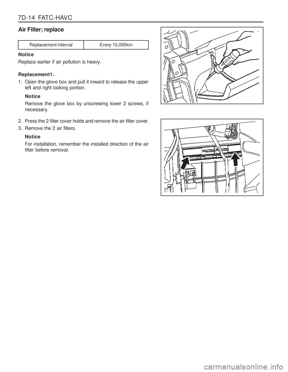
7D-14 FATC-HAVCAir Filter; replace Notice
Replace earlier if air pollution is heavy. Replacement1.
1. Open the glove box and pull it inward to release the upper left and right locking portion. Notice Remove the glove box by unscrewing lower 2 screws, if
necessary.
2. Press the 2 filter cover holds and remove the air filter cover.
3. Remove the 2 air filters. NoticeFor installation, remember the installed direction of the air filter before removal.
Replacement Interval Every 10,000km
Page 1175 of 1574
FATC-HAVC 7D-19
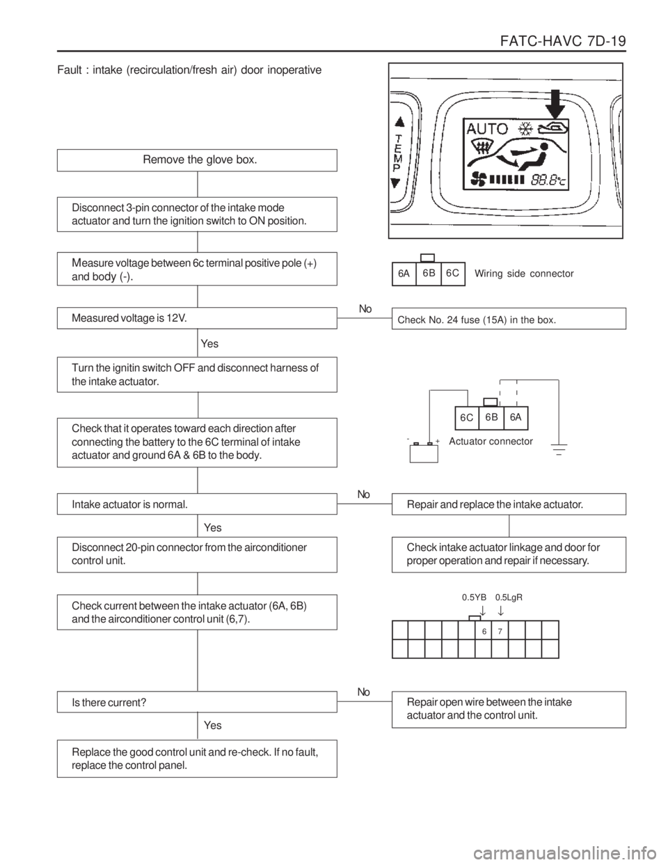
Fault : intake (recirculation/fresh air) door inoperative
Remove the glove box.
Measure voltage between 6c terminal positive pole (+)
and bo dy (-).
Measured voltage is 12V.Check No. 24 fuse (15A) in the box.
Turn the ignitin switch OFF and disconnect harness of
the intake actuator.
Ye s No
Disconnect 3-pin connector of the intake mode actuator and turn the ignition switch to ON position.
6A
6B 6C
Check that it operates toward each direction after connecting the battery to the 6C terminal of intake
actuator and ground 6A & 6B to the body.6C 6B 6A
Wiring side connector
Actuator connector
Intake actuator is normal.
Ye s
Repair and replace the intake actuator.
No
Check intake actuator linkage and door for
proper operation and repair if necessary.Disconnect 20-pin connector from the airconditioner control unit.
Check current between the intake actuator (6A, 6B) and the airconditioner control unit (6,7).
Is there current?
Ye s
Repair open wire between the intake actuator and the control unit.
No
Replace the good control unit and re-check. If no fault, replace the control panel.
67
�
0.5YB
�
0.5LgR
+
-
Page 1201 of 1574
SUPPLEMENTAL RESTRAINT SYSTEM(SRS) 8B-21
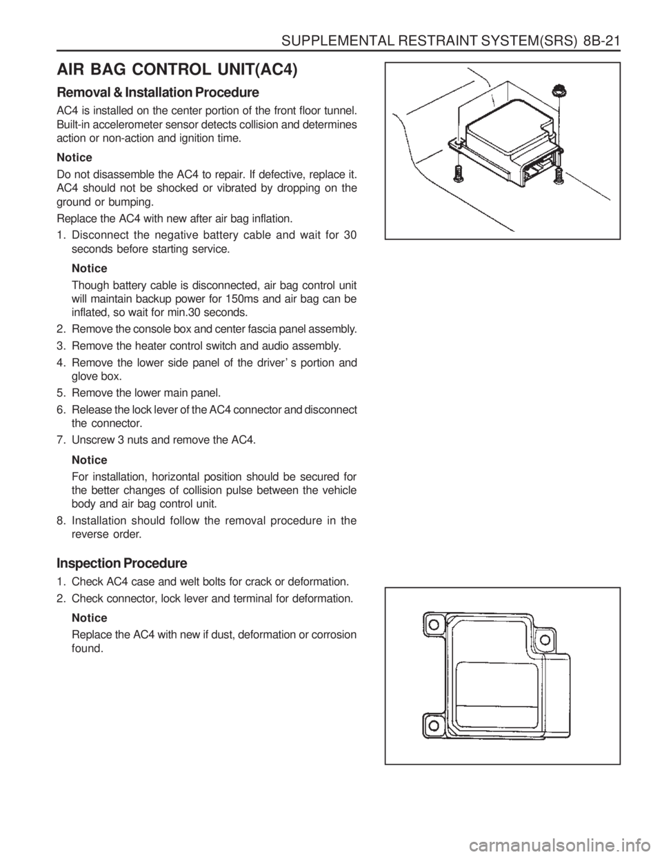
AIR BAG CONTROL UNIT(AC4) Removal & Installation Procedure AC4 is installed on the center portion of the front floor tunnel.
Built-in accelerometer sensor detects collision and determines action or non-action and ignition time. Notice
Do not disassemble the AC4 to repair. If defective, replace it. AC4 should not be shocked or vibrated by dropping on the ground or bumping. Replace the AC4 with new after air bag inflation.
1. Disconnect the negative battery cable and wait for 30seconds before starting service. Notice Though battery cable is disconnected, air bag control unit will maintain backup power for 150ms and air bag can beinflated, so wait for min.30 seconds.
2. Remove the console box and center fascia panel assembly.
3. Remove the heater control switch and audio assembly.
4. Remove the lower side panel of the driver ’ s portion and glove box.
5. Remove the lower main panel.
6. Release the lock lever of the AC4 connector and disconnect the connector.
7. Unscrew 3 nuts and remove the AC4.
NoticeFor installation, horizontal position should be secured for the better changes of collision pulse between the vehiclebody and air bag control unit.
8. Installation should follow the removal procedure in the reverse order.
Inspection Procedure
1. Check AC4 case and welt bolts for crack or deformation.
2. Check connector, lock lever and terminal for deformation. NoticeReplace the AC4 with new if dust, deformation or corrosion found.
Page 1211 of 1574
BODY WIRING SYSTEM 9A-9
44 Joint Connector.................................................... Ground
45 Door Unlock Switch
46 Front Fog Lamp Switch
47 Rear Defogger Switch
4 8 ECS Switch
49 Rear Fog Lamp Switch ........................................Rear Fog Lamp
50 Digital Clock
51 Thermo Amplifier
52 Glove Box Lamp Switch
53 Air Conditioner Wiring Connetor
54 Glove Box Lamp
55 Ground 6
56 Ground 6 ............................................................. Gasoline E/G
57 Ground 7 ............................................................. Gasoline E/G
58 Wheel Speed Sensor (FR) ..................................ABS 5.0 or ABD 5.0
59 O 2 Sensor
............................................................ E32 Gasoline E/G
60 Engine Main Wiring Connector ............................Gasoline E/G with MSE ECU
61 HFM ..................................................................... Gasoline E/G with HFM ECU
61-1 MSE ..................................................................... Gasoline E/G with MSE ECU
62 Front Door Wiring Connector (Passenger Side)
63 Front door Wiring Connector (Passenger Side)
64 Joint Connector (B+)
65 Audio
66 Audio
67 Air Bag Wiring Connector
68 Chime Bell
6 9 Buzzer
70 Kick Down Switch ................................................. Automatic Transmission
71 Diode 2 ................................................................ Manual Transmission
72 Ground 3
73 Ground 4
74 Front Cigarette Lighter
75 Diode 3 ................................................................ Automatic Transmission, MB
76 S/E Mode Selector Switch ....................................Automatic Transmission
76-1 Mode Switch ........................................................ Automatic Transmission
77 “B” Position Switch .............................................. Automatic Transmission
78 “P” Position Switch .............................................. Automatic Transmission
79 Shift Lock Solenoid Valve .....................................Automatic Transmission
8 0 TCCU
81 Ground 5 ............................................................. Gasoline E/G
81-1 Ground 7 ............................................................. Diesel E/G
82 Seat Extension Wiring Connector
83 Transmission Extension Wiring Connector ...........E23 & E32 Gasoline E/G with Manual Transmission
83-1 T ransmission Extension Wiring Connector ...........Diesel E/G with MB A/T
84 Transmission Extension Wiring Connector ...........Gasoline E/G with Manual Transmission
84-1 T ransmission Extension Wiring Connector ...........Diesel E/G with Manual Transmission or BTRE A/T
85 Transmission Extension Wiring Connector ...........E23 & E32 Gasoline E/G with A/T
85-1 T ransmission Extension Wiring Connector ...........Diesel E/G with BTRE A/T
86 Transfer Case Motor
87 Transfer Case Motor
88 Vehicle Speed Sensor
89 Fuel Gauge
90 Acceleration Sensor ............................................. ABS 5.0
91 Seat Belt Switch (Passenger)
92 Seat Heater Switch
93 Head Lamp Leveling Device Switch .....................Leveling Device
Page 1353 of 1574
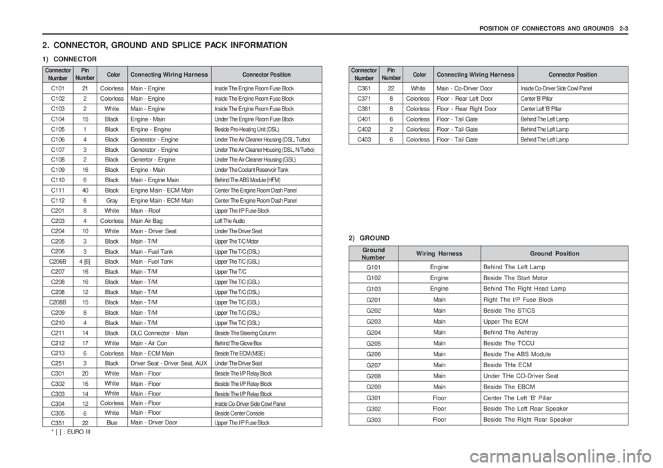
POSITION OF CONNECTORS AND GROUNDS 2-3
C361 C371C381C401C402C403 22
88626 White
ColorlessColorlessColorlessColorlessColorless Main - Co-Driver DoorFloor - Rear Left DoorFloor - Rear Right DoorFloor - Tail GateFloor - Tail GateFloor - Tail Gate
Inside Co-Driver Side Cowl PanelCenter 'B' PillarCenter Left 'B' PillarBehind The Left LampBehind The Left LampBehind The Left Lamp
2. CONNECTOR, GROUND AND SPLICE PACK INFORMATION
1) CONNECTOR
Connector
Number Connecting Wiring HarnessConnector PositionColorPin
Number
C101 C102C103C104C105C106C107 C108 C109C110C111C112C201C203C204C205 C206
C206B C207 C208C208
C208B C209C210C211C212 C213 C251C301C302C303 C304 C305 C351212 2
15 143 2
16 6
40 6 84
10 33
4 [6]
1616121584
1417 6 3
20 1614 12 6
22 Colorless Colorless
WhiteBlackBlackBlackBlack Black BlackBlackBlack Gray
White
Colorless WhiteBlackBlack Black BlackBlackBlackBlackBlackBlackBlack
White
Colorless Black
White WhiteWhite
Colorless White
Blue Main - Engine Main - EngineMain - EngineEngine - MainEngine - EngineGenerator - EngineGenerator - Engine Genertor - Engine Engine - MainMain - Engine MainEngine Main - ECM MainEngine Main - ECM MainMain - RoofMain Air BagMain - Driver SeatMain - T/MMain - Fuel Tank Main - Fuel Tank Main - T/MMain - T/MMain - T/MMain - T/MMain - T/MMain - T/MDLC Connector - MainMain - Air ConMain - ECM Main Driver Seat - Driver Seat, AUX Main - FloorMain - Floor Main - Floor Main - FloorMain - Floor Main - Driver DoorInside The Engine Room Fuse Block Inside The Engine Room Fuse BlockInside The Engine Room Fuse BlockUnder The Engine Room Fuse BlockBeside Pre-Heating Unit (DSL)Under The Air Cleaner Housing (DSL, Turbo)Under The Air Cleaner Housing (DSL, N/Turbo) Under The Air Cleaner Housing (GSL) Under The Coolant Reservoir TankBehind The ABS Module (HFM)Center The Engine Room Dash PanelCenter The Engine Room Dash PanelUpper The I/P Fuse BlockLeft The AudioUnder The Driver SeatUpper The T/C MotorUpper The T/C (DSL) Upper The T/C (GSL) Upper The T/CUpper The T/C (GSL)Upper The T/C (DSL)Upper The T/C (GSL)Upper The T/C (DSL)Upper The T/C (GSL)Beside The Steering ColumnBehind The Glove BoxBeside The ECM (MSE) Under The Driver Seat Beside The I/P Relay BlockBeside The I/P Relay BlockBeside The I/P Relay Block Inside Co-Driver Side Cowl Panel Beside Center ConsoleUpper The I/P Fuse Block
Connector
Number Connecting Wiring HarnessConnector PositionColorPin
Number
2) GROUND
G101 G102 G103G201 G202 G203G204G205 G206 G207G208 G209 G301G302G303 Ground Position
Wiring Harness
Ground
Number
Behind The Left LampBeside The Start Motor Behind The Right Head Lamp Right The I/P Fuse BlockBeside The STICSUpper The ECM Behind The Ashtray Beside The TCCUBeside The ABS Module Beside THe ECM Under THe CO-Driver SeatBeside The EBCMCenter The Left 'B' Pillar Beside The Left Rear Speaker Beside The Right Rear Speaker
Engine Engine Engine
Main MainMain Main MainMain Main MainMain
Floor Floor Floor
* [ ] : EURO III
Page 1468 of 1574
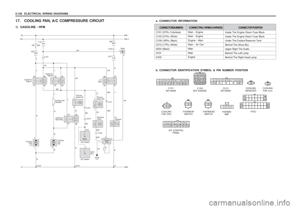
5-102 ELECTRICAL WIRING DIAGRAMS
17. COOLING FAN, A/C COMPRESSURE CIRCUIT
1) GASOLINE - HFM
C101
W/H MAIN
12345 678910
11 12 13 14 15 16 17 18 19 20 21
Main - Engine Main - Engine Engine - Main Main - Air Con MainMain Engine
C101 (21Pin, Colorless) C103 (21Pin, White)C109 (16Pin, Black) C212 (17Pin, White) S204 (Black) G101 G103
b. CONNECTOR IDENTIFICATION SYMBOL & PIN NUMBER POSITION
a. CONNECTOR INFORMATION
CONNECTOR(NUMBER)
CONNECTING. WIRING HARNESSCONNECTOR POSITION
Inside The Engine Room Fuse Block Inside The Engine Room Fuse Block Under The Coolant Reservoir Tank Behind The Glove BoxUpper Right The Audio Behind The Left Lamp Behind The Right Head Lamp
COOLING
RESISTER
12
C109
W/H ENGINEC212
W/H MAIN
12345 678910
11 12 13 14 15 16 17
COOLING FAN (LH)
12
12121234
A1 A9 A8A16
B1B11 B20
B10
1234 567
8 9 10 11 12 13 14 15 16
12
COOLING
FAN (RH) THERMO#1
SWITCH THERMO#2
SWITCH THERMO
AMP FATC
A/C CONTROL PANEL
Cooling FanRelay #2
Cooling Fan Relay #130 86
87
BG BG
85
Ef5
30A
G103 G101B
B
LB
L
L LW
LWLW
LW
L R
M
1
1
2 R
R
R B
L
L
LY Y
B B
Cooling
Fa nLH
30 86
87 85 1
5
S204
F19
10A
A/C
Relay30
86
87
85
Cooling Fan
Motor Relay30
86
87 85
11
C101
1
C103
Ef8
60A
Ef17
10A
C1013 C101
8
C212
11 C109
7
A16
FAT C
SATC/ MTC
A/C Switch A/C Switch G
LW
BW BW
BG
BrR
BrR BY
A/C Compressor
2 1Thermo Switch #2
P
Receiver
Dryer
2
4
3
1Thermo AmpM
1
2 Cooling
Fa nRH
1
2 Cooling Fan Resister
ECM"11"1
2 C
C
Thermo Switch #1
30
BAT+
15A IGN 2
31 GND
Ef2 80A
Page 1470 of 1574
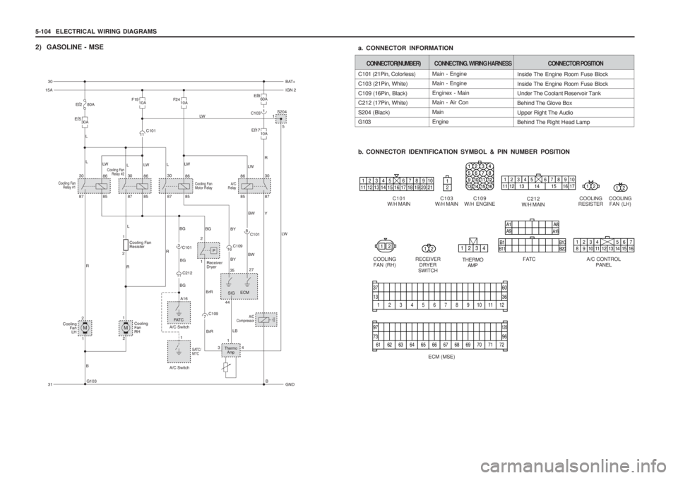
5-104 ELECTRICAL WIRING DIAGRAMS
2) GASOLINE - MSE
C101
W/H MAIN
12345 678910
11 12 13 14 15 16 17 18 19 20 21
Main - Engine Main - Engine Enginex - Main Main - Air Con MainEngine
C101 (21Pin, Colorless)C103 (21Pin, White)C109 (16Pin, Black) C212 (17Pin, White) S204 (Black) G103
b. CONNECTOR IDENTIFICATION SYMBOL & PIN NUMBER POSITION
a. CONNECTOR INFORMATION
CONNECTOR(NUMBER)
CONNECTING. WIRING HARNESSCONNECTOR POSITION
Inside The Engine Room Fuse Block Inside The Engine Room Fuse Block Under The Coolant Reservoir Tank Behind The Glove BoxUpper Right The Audio Behind The Right Head Lamp
COOLING
RESISTER
12
C109
W/H ENGINEC212
W/H MAIN
12345 678910
11 12 13 14 15 16 17
COOLING FAN (LH)
12
12121234
A1 A9 A8A16
B1B11 B20
B101234 567
8 9 10 11 12 13 14 15 16
COOLING
FAN (RH) RECEIVER
DRYER
SWITCH THERMO
AMP FATC
A/C CONTROL
PANEL
1
13
37
36
60
23456789101112
61
73
97
96
120
62 63 64 65 66 67 68 69 70 71 72
ECM (MSE)C103
W/H MAIN
Cooling Fan Relay #2
Cooling Fan Relay #130 86
87
BGBG
BG
85
Ef5
30A
G103 B
L
L LW LWLWLW
LW
L
L R
M
1
1
2 R
RL
Y
R
B
Cooling
FanLH
30 86
87 85 1
5
S204
F19
10A
A/C
Relay30
86
87
85Cooling Fan
Motor Relay
30
86
87 85
11C101
1
C103
Ef8
60A
Ef17
10A
C1013 C101
8
C212
11 C109
7C109
16
A16
FAT C
SATC/ MTC
A/C Switch
A/C Switch BG
BY BY LW
BW
BW
BrR SIG
BrR
A/C
Compressor
LB
2 1
P
Receiver
Dryer
35
44 27
ECM
34 1Thermo
Amp
M
1
2 Cooling
Fa nRH
1
2 Cooling Fan Resister
30
BAT+
15A IGN 2
31 GND
F24
10AEf2 80A
1
2