2003 SSANGYONG MUSSO solenoid
[x] Cancel search: solenoidPage 1227 of 1574
BODY WIRING SYSTEM 9A-25
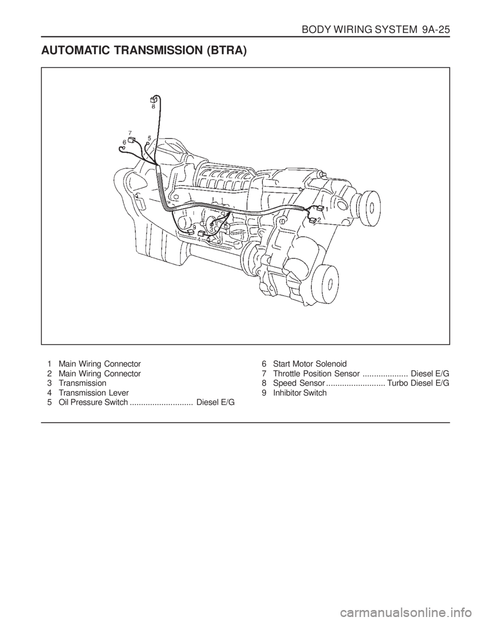
AUTOMATIC TRANSMISSION (BTRA)1 Main Wiring Connector
2 Main Wiring Connector
3 Transmission
4 Transmission Lever
5 Oil Pressure Switch ............................Diesel E/G6 Start Motor Solenoid
7 Throttle Position Sensor
....................Diesel E/G
8 Speed Sensor .......................... T urbo Diesel E/G
9 Inhibitor Switch
Page 1315 of 1574
MUSSO-SPORTS 1A-3
SUPPLEMENT
HUBER EGR
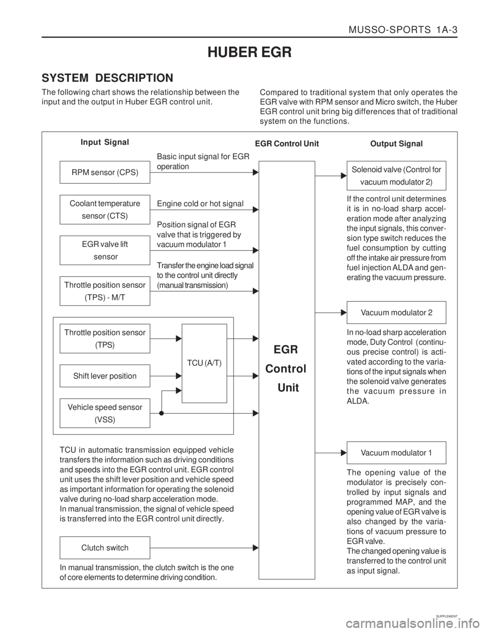
SYSTEM DESCRIPTION The following chart shows the relationship between the input and the output in Huber EGR control unit. Compared to traditional system that only operates theEGR valve with RPM sensor and Micro switch, the HuberEGR control unit bring big differences that of traditionalsystem on the functions.
Input Signal
RPM sensor (CPS)
EGR valve lift sensor
Throttle position sensor (TPS) - M/T
Shift lever position
Throttle position sensor (TPS)
Vehicle speed sensor(VSS) Basic input signal for EGR operation Engine cold or hot signal
Position signal of EGR valve that is triggered by vacuum modulator 1 Transfer the engine load signal to the control unit directly (manual transmission)
TCU (A/T)
EGR
Control
Unit
Coolant temperature sensor (CTS)
Solenoid valve (Control forvacuum modulator 2)
If the control unit determines it is in no-load sharp accel- eration mode after analyzing the input signals, this conver- sion type switch reduces the fuel consumption by cutting off the intake air pressure from
fuel injection ALDA and gen- erating the vacuum pressure. In no-load sharp acceleration
mode, Duty Control ( continu- ous precise control) is acti- vated according to the varia- tions of the input signals when the solenoid valve generates the vacuum pressure in ALDA.
Vacuum modulator 2
The opening value of the modulator is precisely con- trolled by input signals and programmed MAP, and the opening value of EGR valve is also changed by the varia- tions of vacuum pressure to EGR valve. The changed opening value is transferred to the control unit as input signal.
Vacuum modulator 1
TCU in automatic transmission equipped vehicle transfers the information such as driving conditions and speeds into the EGR control unit. EGR control unit uses the shift lever position and vehicle speed as important information for operating the solenoid valve during no-load sharp acceleration mode. In manual transmission, the signal of vehicle speed is transferred into the EGR control unit directly.
Clutch switch
In manual transmission, the clutch switch is the one of core elements to determine driving condition. Output Signal
EGR Control Unit
Page 1316 of 1574
1A-4 MUSSO-SPORTS
SUPPLEMENT
from vacuum pump
EGR valve
EGR control unit
KAA5A020
KAA5A020
KAA5A020
KAA5A020 EGR COMPONENTS EGR Unit
1. Location: behind passenger's side panel
2. Arrangement: 81-pin connector
3. Integrated self-diagnostic function (Scan-100: not
fixed)
4. Part number For automatic transmission: 28800-07100 For manual transmission: 28800-07000
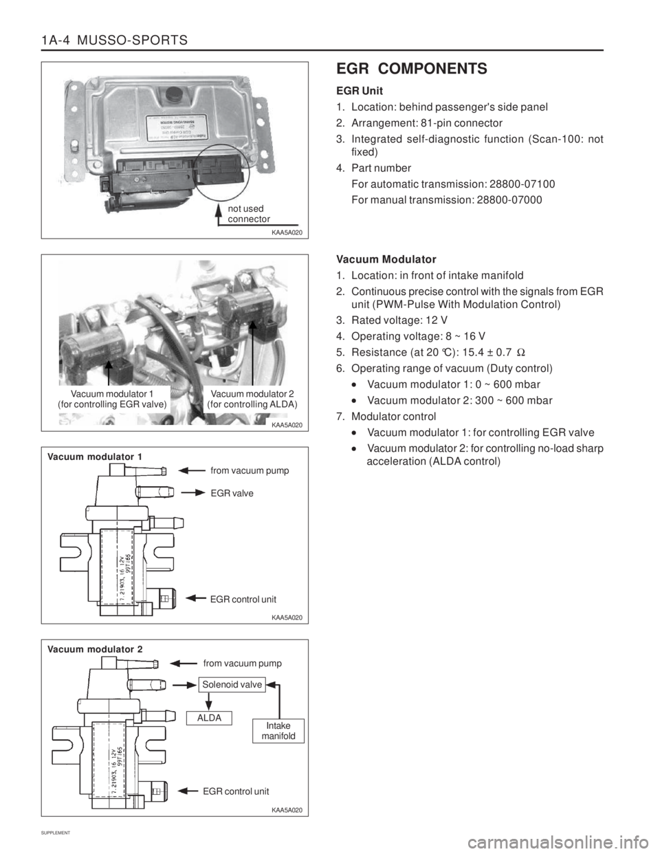
Vacuum Modulator
1. Location: in front of intake manifold
2. Continuous precise control with the signals from EGR unit (PWM-Pulse With Modulation Control)
3. Rated voltage: 12 V
4. Operating voltage: 8 ~ 16 V
5. Resistance (at 20 °C): 15.4 ± 0.7 �
6. Operating range of vacuum (Duty control)
Vacuum modulator 1: 0 ~ 600 mbar
Vacuum modulator 2: 300 ~ 600 mbar
7. Modulator control
Vacuum modulator 1: for controlling EGR valve
Vacuum modulator 2: for controlling no-load sharp
acceleration (ALDA control)
not used connector
Vacuum modulator 1
(for controlling EGR valve)Vacuum modulator 2
(for controlling ALDA)
from vacuum pump
Vacuum modulator 1
Vacuum modulator 2
Solenoid valve
ALDAIntake
manifold
EGR control unit
Page 1318 of 1574
1A-6 MUSSO-SPORTS
SUPPLEMENT
Coolant Temperature Sensor (CTS)
1. Location: on cylinder block
2. Coolant temperature MAP (4 Stages) T0: 10 ~ 24 °C
T1: 25 ~ 40 °C
T2: 41 ~ 61 °C
T3: above 61 °C
3. If the EGR system is normally defective while engine is cold (or during warming up), it may be caused by incorrect input signal of the coolant temperaturesensor.
4. Resistance between pin 1 and pin 4 of the connector 20 °C: 2250 ± 159.0 �
50 °C: 836 ± 41.5 �
80 °C: 321 ± 15.0 �
120 °C: 113 ± 7.2 �
KAA5A040 KAA5A060
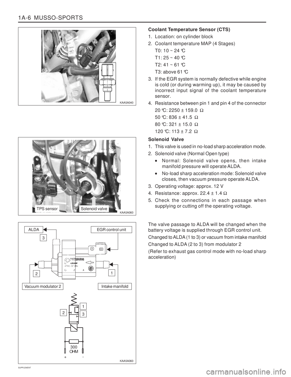
KAA5A060Solenoid Valve
1. This valve is used in no-load sharp acceleration mode.
2. Solenoid valve (Normal Open type)
Normal: Solenoid valve opens, then intake
manifold pressure will operate ALDA.
No-load sharp acceleration mode: Solenoid valve
closes, then vacuum pressure operate ALDA.
3. Operating voltage: approx. 12 V
4. Resistance: approx. 22.4 ± 1.4 �
5. Check the connections in each passage when supplying or cutting off the operating voltage.
The valve passage to ALDA will be changed when the battery voltage is supplied through EGR control unit.
Changed to ALDA (1 to 3) or vacuum from intake manifold
Changed to ALDA (2 to 3) from modulator 2 (Refer to exhaust gas control mode with no-load sharp acceleration)
TPS sensorSolenoid valve
Intake manifold
ALDAEGR control unit
3
12
Vacuum modulator 2
2
1
3
300
OHM
+-
Page 1322 of 1574
1A-10 MUSSO-SPORTS
SUPPLEMENT
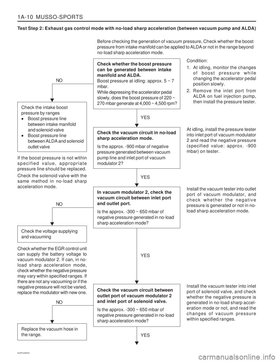
Test Step 2: Exhaust gas control mode with no-load sharp acceleration (between vacuum pump and ALDA)
Condition:
1. At idling, monitor the changesof boost pressure while changing the accelerator pedalposition slowly.
2. Remove the inlet port from ALDA on fuel injection pump,then install the pressure tester.
Before checking the generation of vacuum pressure, Check whether the boost
pressure from intake manifold can be applied to ALDA or not in the range beyond no-load sharp acceleration mode. Check whether the boost pressure can be generated between intake manifold and ALDA. Boost pressure at idling: approx. 5 ~ 7 mbar. While depressing the accelerator pedal slowly, does the boost pressure of 220 ~ 270 mbar generate at 4,000 ~ 4,500 rpm?
At idling, install the pressure tester into inlet port of vacuum modulator2 and read the negative pressure(specified value: approx. -900mbar) on tester. Install the vacuum tester into inlet port of solenoid valve, and checkwhether the negative pressure isgenerated in no-load sharp accel-eration mode or not, and read thechanges of vacuum pressurewithin specified ranges.
NO
If the boost pressure is not within specified value, appropriatepressure line should be replaced. Check the solenoid valve with the same method in no-load sharpacceleration mode.
YES
YES
Check the vacuum circuit in no-load sharp acceleration mode. Is the approx. -900 mbar of negative pressure generated between vacuum pump line and inlet port of vacuum modulator 2?
In vacuum modulator 2, check the vacuum circuit between inlet port and outlet port. Is the approx. -300 ~ 650 mbar of negative pressure generated in no-load sharp acceleration mode?
Check the vacuum circuit between outlet port of vacuum modulator 2 and inlet port of solenoid valve. Is the approx. -300 ~ 650 mbar of negative pressure generated in no-load sharp acceleration mode?
Install the vacuum tester into outlet port of vacuum modulator, andcheck whether the negativepressure is generated or not in no-load sharp acceleration mode.
Check the intake boost pressure by ranges
Boost pressure line
between intake manifold and solenoid valve
Boost pressure line
between ALDA and solenoid outlet valve
NO
Check the voltage supplying and vacuuming
Check whether the EGR control unit can supply the battery voltage tovacuum modulator 2. If can, in no-load sharp acceleration mode,check whether the negative pressuremay vary within specified ranges. Ifthere are not any vacuuming or if thenegative pressure will not be varied,replace the modulator with new one. YES
YES
NO
Replace the vacuum hose in the range.
Page 1323 of 1574
MUSSO-SPORTS 1A-11
SUPPLEMENT
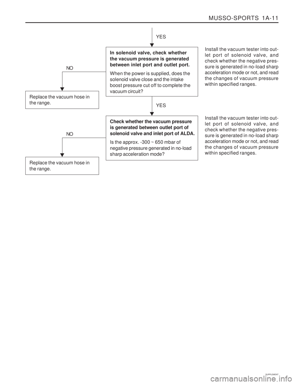
Install the vacuum tester into out- let port of solenoid valve, andcheck whether the negative pres-sure is generated in no-load sharpacceleration mode or not, and readthe changes of vacuum pressurewithin specified ranges.
YES
In solenoid valve, check whether the vacuum pressure is generated between inlet port and outlet port. When the power is supplied, does the solenoid valve close and the intake boost pressure cut off to complete the vacuum circuit?
NO
Replace the vacuum hose in the range.
Install the vacuum tester into out- let port of solenoid valve, andcheck whether the negative pres-sure is generated in no-load sharpacceleration mode or not, and readthe changes of vacuum pressurewithin specified ranges.
YES
Check whether the vacuum pressure is generated between outlet port of solenoid valve and inlet port of ALDA. Is the approx. -300 ~ 650 mbar of negative pressure generated in no-load
sharp acceleration mode?
NO
Replace the vacuum hose in the range.
Page 1325 of 1574
MUSSO-SPORTS 1A-13
SUPPLEMENT
KAA5A020
KAA5A020
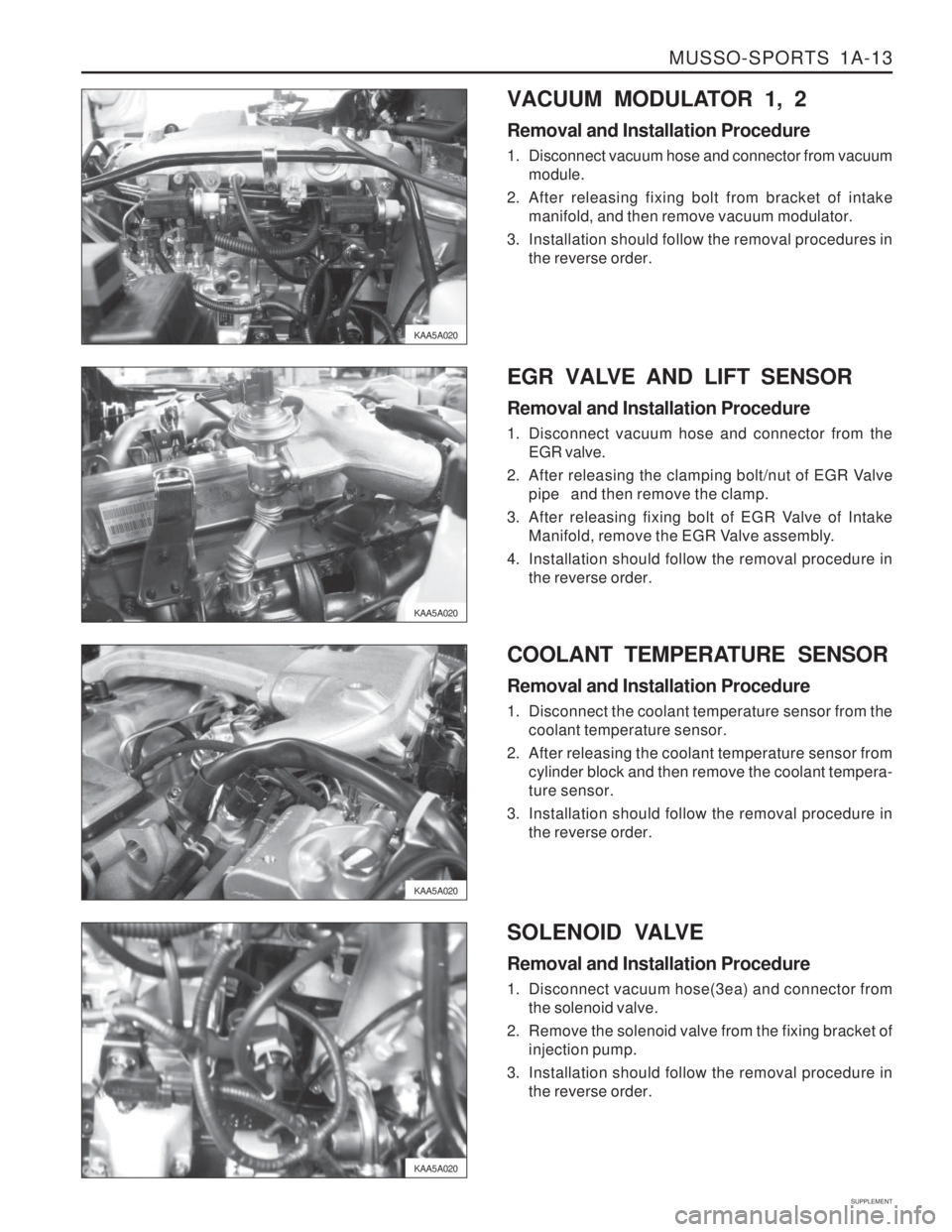
KAA5A020VACUUM MODULATOR 1, 2 Removal and Installation Procedure
1. Disconnect vacuum hose and connector from vacuum
module.
2. After releasing fixing bolt from bracket of intake manifold, and then remove vacuum modulator.
3. Installation should follow the removal procedures in the reverse order.
KAA5A020 EGR VALVE AND LIFT SENSOR Removal and Installation Procedure
1. Disconnect vacuum hose and connector from the
EGR valve.
2. After releasing the clamping bolt/nut of EGR Valve pipe and then remove the clamp.
3. After releasing fixing bolt of EGR Valve of Intake Manifold, remove the EGR Valve assembly.
4. Installation should follow the removal procedure in the reverse order.
COOLANT TEMPERATURE SENSOR Removal and Installation Procedure
1. Disconnect the coolant temperature sensor from the coolant temperature sensor.
2. After releasing the coolant temperature sensor from cylinder block and then remove the coolant tempera- ture sensor.
3. Installation should follow the removal procedure in the reverse order.
SOLENOID VALVE Removal and Installation Procedure
1. Disconnect vacuum hose(3ea) and connector from the solenoid valve.
2. Remove the solenoid valve from the fixing bracket of injection pump.
3. Installation should follow the removal procedure in the reverse order.
Page 1369 of 1574
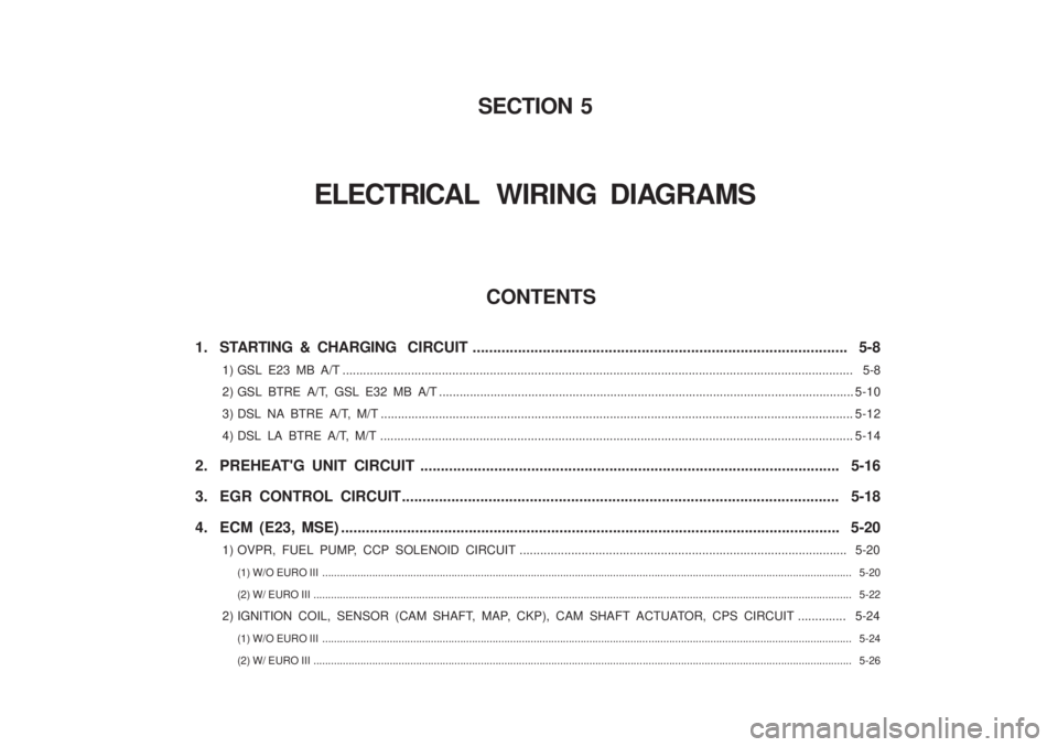
CONTENTS
1. STARTING & CHARGING CIRCUIT ........................................................................................... 5-8
1) GSL E23 MB A/T ............................................................................................................... ...................................... 5-8
2) GSL BTRE A/T, GSL E32 MB A/T ................................................................................................. ........................5-10
3) DSL NA BTRE A/T, M/T ......................................................................................................... .................................5-12
4) DSL LA BTRE A/T, M/T ......................................................................................................... .................................5-14
2. PREHEAT'G UNIT CIRCUIT ...................................................................................................... 5-16
3. EGR CONTROL CIRCUIT.......................................................................................................... 5-18
4. ECM (E23, MSE) ............................................................................................................... .......... 5-20
1) OVPR, FUEL PUMP, CCP SOLENOID CIRCUIT ........................................................................................ ....... 5-20
(1) W/O EURO III ............................................................................................................... ..................................................................... 5-20
(2) W/ EURO III ................................................................................................................ ....................................................................... 5-22
2) IGNITION COIL, SENSOR (CAM SHAFT, MAP, CKP), CAM SHAFT ACTUATOR, CPS CIRCUIT .............. 5-24 (1) W/O EURO III ............................................................................................................... ..................................................................... 5-24
(2) W/ EURO III ................................................................................................................ ....................................................................... 5-26
SECTION 5
ELECTRICAL WIRING DIAGRAMS