Page 623 of 1574
OM600 ENGINE CONTROLS 1F3-13
VACUUM PUMP Preceding Work : Remove the poly V-belt
1 Bolt............................................................ 10Nm
2 Vacuum Pump
3 Vacuum Line (Ancillaries) 4 Vacuum Line (Brake Booster)
5 Gasket ................................................... Replace
Page 712 of 1574

2B-2 WHEEL ALIGNMENT
DIAGNOSIS
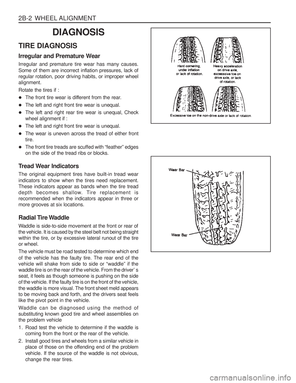
TIRE DIAGNOSIS Irregular and Premature Wear Irregular and premature tire wear has many causes. Some of them are incorrect inflation pressures, lack of regular rotation, poor driving habits, or improper wheelalignment. Rotate the tires if :
� The front tire wear is different from the rear.
� The left and right front tire wear is unequal.
� The left and right rear tire wear is unequal, Check wheel alignment if :
� The left and right front tire wear is unequal.
� The wear is uneven across the tread of either fronttire.
� The front tire treads are scuffed with “feather” edgeson the side of the tread ribs or blocks.
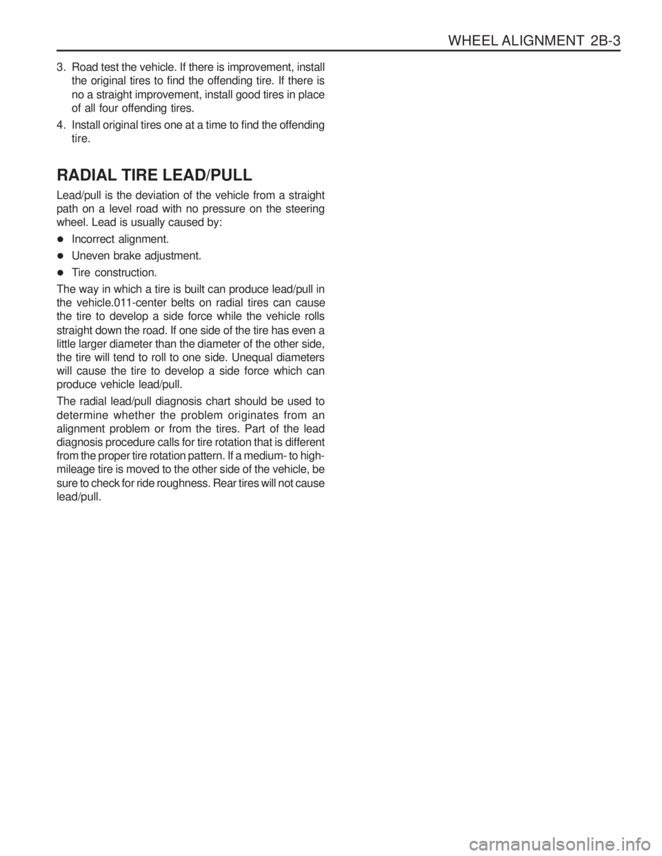
Tread Wear Indicators The original equipment tires have built-in tread wear indicators to show when the tires need replacement. These indicators appear as bands when the tire tread
depth becomes shallow. Tire replacement isrecommended when the indicators appear in three ormore grooves at six locations.
Radial Tire Waddle
Waddle is side-to-side movement at the front or rear of the vehicle. It is caused by the steel belt not being straightwithin the tire, or by excessive lateral runout of the tireor wheel. The vehicle must be road tested to determine which end of the vehicle has the faulty tire. The rear end of the vehicle will shake from side to side or “waddle” if the
waddle tire is on the rear of the vehicle. From the driver’ sseat, it feels as though someone is pushing on the sideof the vehicle. If the faulty tire is on the front of the vehicle, the waddle is more visual. The front sheet meld appears to be moving back and forth, and the drivers seat feelslike the pivot point in the vehicle.
Waddle can be diagnosed using the method of substituting known good tire and wheel assemblies onthe problem vehicle
1. Road test the vehicle to determine if the waddle is coming from the front or the rear of the vehicle.
2. Install good tires and wheels from a similar vehicle in place of those on the offending end of the problem vehicle. If the source of the waddle is not obvious, change the rear tires.
Page 713 of 1574

WHEEL ALIGNMENT 2B-3
3. Road test the vehicle. If there is improvement, installthe original tires to find the offending tire. If there is no a straight improvement, install good tires in place of all four offending tires.
4. Install original tires one at a time to find the offending tire.
RADIAL TIRE LEAD/PULL Lead/pull is the deviation of the vehicle from a straight path on a level road with no pressure on the steeringwheel. Lead is usually caused by:
� Incorrect alignment.
� Uneven brake adjustment.
� Tire construction.
The way in which a tire is built can produce lead/pull in
the vehicle.011-center belts on radial tires can causethe tire to develop a side force while the vehicle rolls straight down the road. If one side of the tire has even a little larger diameter than the diameter of the other side,the tire will tend to roll to one side. Unequal diameterswill cause the tire to develop a side force which canproduce vehicle lead/pull. The radial lead/pull diagnosis chart should be used to determine whether the problem originates from an alignment problem or from the tires. Part of the leaddiagnosis procedure calls for tire rotation that is differentfrom the proper tire rotation pattern. If a medium- to high-mileage tire is moved to the other side of the vehicle, be sure to check for ride roughness. Rear tires will not cause lead/pull.
Page 1144 of 1574

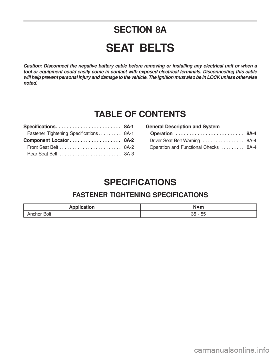
6A-2 POWER STEERING SYSTEMChecks
Damaged or Binding Steering Ball Joint Improper Preload of Steering Pinion
Damaged Wheel or TireFaulty Suspension System Checks
Worn Steering Gear Worn or Damaged Steering Ball Joint Loosened Steering Gearbox Bolts Checks
Damaged Steering Linkage
Damaged Wheel and Tire Faulty Brake System Faulty Suspension System Checks
Lack of Lubrication Abnormal Wear or Binding of Steering Ball Joint Damaged or Faulty Steering GearImproper Preload of Steering PinionFaulty Steering Shaft JointSteering Fluid Leaks Lack of Fluid or Air-in System Faulty Steering Oil PumpDamaged or Loosened Pump Drive BeltClogging Oil Line
Damaged Wheel or Tire Faulty Suspension System DIAGNOSIS
HARD STEERING
Action
Lubricate
Replace
Replace gear assembly
Adjust
Replace
Repair or replace
Replenish or bleed Replace
Adjust or replace
Repair or replace Repair or replace Repair or replace
STEERING PULLS TO ONE SIDE
Action Repair
Repair or replace Repair or replace Repair or replace
EXCESSIVE WHEEL PLAY
Action
Replace gear assembly
Replace
Retighten
POOR RETURN OF STEERING WHEEL
Action
Replace
Replace gear assembly Repair or replace Repair or replace
Page 1145 of 1574
POWER STEERING SYSTEM 6A-3
Checks
Loosened Steering Gearbox Mounting Bolt Faulty Steering Gear Steering Column LinterferenceLoosened Steering LinkageDamaged or Loosened Oil Pump Drive BeltLoosened Oil Pump Bracket Loosened Oil Pump Mounting Bolt Air-in SystemFaulty Oil Pump Checks
Damaged Steering LinkageLoosened Steering Gearbox Mounting Bolt Damaged or Binding Steering Ball Joint Worn or Damaged Front Wheel Bearing
Damaged Wheel or TireFaulty Suspension System STEERING WHEEL SHIMMY
Action
Replace
Retighten
Replace Replace
Repair or replaceRepair or replace
ABNORMAL NOISE FROM STEERING SYSTEM
Action
Retighten
Replace gear assembly Replace
Retighten
Adjust or replace Retighten RetightenBleed
Replace
Page 1177 of 1574

SECTION 8A
SEAT BELTS
Specifications . . . . . . . . . . . . . . . . . . . . . . . . 8A-1
Fastener Tightening Specifications . . . . . . . . . 8A-1
Component Locator . . . . . . . . . . . . . . . . . . . 8A-2
Front Seat Belt . . . . . . . . . . . . . . . . . . . . . . . . 8A-2
Rear Seat Belt . . . . . . . . . . . . . . . . . . . . . . . . 8A-3 TABLE OF CONTENTS
Caution: Disconnect the negative battery cable before removing or installing any electrical unit or when a tool or equipment could easily come in contact with exposed electrical terminals. Disconnecting this cable will help prevent personal injury and damage to the vehicle. The ignition must also be in LOCK unless otherwisenoted.
General Description and System
Operation . . . . . . . . . . . . . . . . . . . . . . . . . 8A-4
Driver Seat Belt Warning . . . . . . . . . . . . . . . . 8A-4
Operation and Functional Checks . . . . . . . . . 8A-4
SPECIFICATIONS
FASTENER TIGHTENING SPECIFICATIONS
Application
Anchor Bolt N
�m
35 - 55
Page 1178 of 1574
8A-2 SEAT BELTCOMPONENT LOCATOR
FRONT SEAT BELT
1 Seat Belt Assembly (3-Point)
2 Buckle Assembly
3 Seat Belt Dust Cover
4 Seat Belt Webbing Guide
5 Seat Belt Reel Assembly
6 Anchor Bolt .......................................... 35-55 Nm
7 Anchor Bolt .......................................... 35-55 Nm
8 Anchor Bolt .......................................... 35-55 Nm
Page 1179 of 1574
SEAT BELTS 8A-3
REAR SEAT BELT1 Seat Belt Assembly (3-point)
2 Seat Belt Stalk Plate Assembly
3 Seat Belt Assembly (2-Point)
4 Webbing Buckle Assembly (Center)
5 Webbing Buckle Assembly (Rear)
6 Webbing Hanger
7 Seat Belt Dust Cover
8 Webbing Guide