Page 506 of 1574
1E1-6 M162 ENGINE ELECTRICAL
BATTERY
1 Cable Terminal (-)
2 Cable Terminal Cap (-)
3 Cable Terminal Cap (+)
4 Nut
5 Fuseblink Box
6 Terminal (+)7 Battery holddown Bracket
8 Battery Clamp Bolt
9 Battery
10 Sub Tray 11 Battery Tray
Removal & Installation Procedure Notice
� Disconnect the battery negative cable first.
� Insert the clamp bolt (8) into the battery tray hole (11)
from inside when installing.
Page 518 of 1574
1E2-6 M161 ENGINE ELECTRICAL
BATTERY
1 Cable Terminal (-)
2 Cable Terminal Cap (-)
3 Cable Terminal Cap (+)
4 Nut
5 Fuseblink Box
6 Terminal (+)7 Battery holddown Bracket
8 Battery Clamp Bolt
9 Battery
10 Sub Tray 11 Battery Tray
Removal & Installation Procedure Notice
� Disconnect the battery negative cable first.
� Insert the clamp bolt (8) into the battery tray hole (11)
from inside when installing.
Page 564 of 1574
1F1-32 M162 ENGINE CONTROLS
Failurecode ItemChecking method
Test
stepRequirementSpecified
value Possible cause
1 liter of fuel supply formax. 35
seconds
Fuel pump:
- Fuel supply ratio
Ignition:ON
- Disconnect the fuel return pipe and connect the host tobeaker to collect thesupplied fuel
�
1.0
� 2.0
Check the fuel line
5 - 9 A
Fuel pump:
- Current consumption
Ignition:ON
- Remove the fuel relay from the fuseand relay box inluggagecompartment andconnect theamperemeterbetween No.1 andNo.3 in relaybox(fuel pump relay removed position) for measuringcurrent consumption
�
2.0
Fuel pump
53 3
Multi tester(DC current)
31
Page 593 of 1574
M162 ENGINE CONTROLS 1F1-61
Notice Replace the fuel pump relay if the measured value is over 9A.
Notice Check the fuel filter and fuel line when the fuel delivery is not within specified value.
Measure the Current Consumption of Fuel Pump
1. Remove the fuel pump relay from fuse and relay box in trunk, and turn the ignition switch to "ON" position.
2. Using a multi-tester, measure the current consumption by connecting the terminal No.1 and No.3 of pump.
Measure the Fuel Delivery From the Fuel Pump
1. Disconnect the return pipe from fuel distributor and insert
the appropriate hose into it.
2 . Place the hose end into the beaker with the minimum capacity of 1Liter.
3. Turn the ignition switch to "ON" position.
4. Connect the terminal No.33 and No.5 of ECU with a service wire.
5. Measure the fuel delivery from the fuel pump.
1Liter/max.35sec.
Specifed Value
5 - 9A
Specifed Value
Page 1107 of 1574
5D2-18 TRANSFER CASE (TOD) CODING
Coding Tool SCANNER
Connection of Coding Tool Construct SCANNER into diagnosis connector (20 pins) near fuse box in engine room as below figure.
1 Diagnosis Connector2 SCANNER
Notice Coding ; An input activity of data for the proper performance by matching specification, devices andsystem with control unit.
Page 1110 of 1574

TRANSFER CASE (TOD) 5D2-21
DIAGNOSIS Malfunction interior TOD control unit ; fault code 1714
�Phenomenon
1. When ignition “ON ”, “4WD CHECK ” lamp illuminates
continuously.
2. On diagnosis by SCAN-100, it displays fault code “1714 ”.
� Cause ; Error of EEPROM checksum in TOD control unit
Test Stage / Contents
Result
Stage T est Contents and Procedure Specified Value
/Yes/No Countermeasure
Check power supply for TOD control unit. 1. Disconnect 30 pin connector from TOD control unit.
2. Ignition “ON ”.
3. Using multi-tester, measure voltage between pin 5(+)
and 17/18 (-). - Specified value - Measured value is within specified range ? 11-14 Vdc
Ye sNo Perform A2 stagePerform A3 stage
Check connection status in TOD control unit connector.
1. Check connection status.
- Is it connected exactly?
2. In case of mal-connection, connect tightly then perform the follows.
a. Delete fault code using Scan-100.
b. Ignition “OFF ”.
c. Ignition “ON ”.
d. Diagnose by Scan-100.
- Does it display fault code “1714 ”? Ye s
No
Ye s No
Check short of 10A fuse (fuse No.20).
1. Detach No.20 fuse from engine room fuse box.
2. Check the existence of short.
- Is fuse normal? Yes
No
Check ground of TOD control unit.
1. Ignition “ON ”.
2. Check voltage between 4/19 (+) pin and 17/18 (-)
using multi-tester (keep connection status).
- Specified value (battery is good)
- Measured value
3. Check short between 17/18 pin and body after disconnect 30 pin connector.
- Is resistance " �"? 12Vdc (battery
voltage)
Ye s
No
Ye sNo
A1 A2 A3 A4
Perform A3 stage Perform A2 stage Perform A3 stage Normal system Perform A4 stage Replace fuse, then perform A1 stage Perform A4-3 stage Replace TOD controlunit Repair ground wiring Ground is O.K., perform A5 stage
Page 1175 of 1574

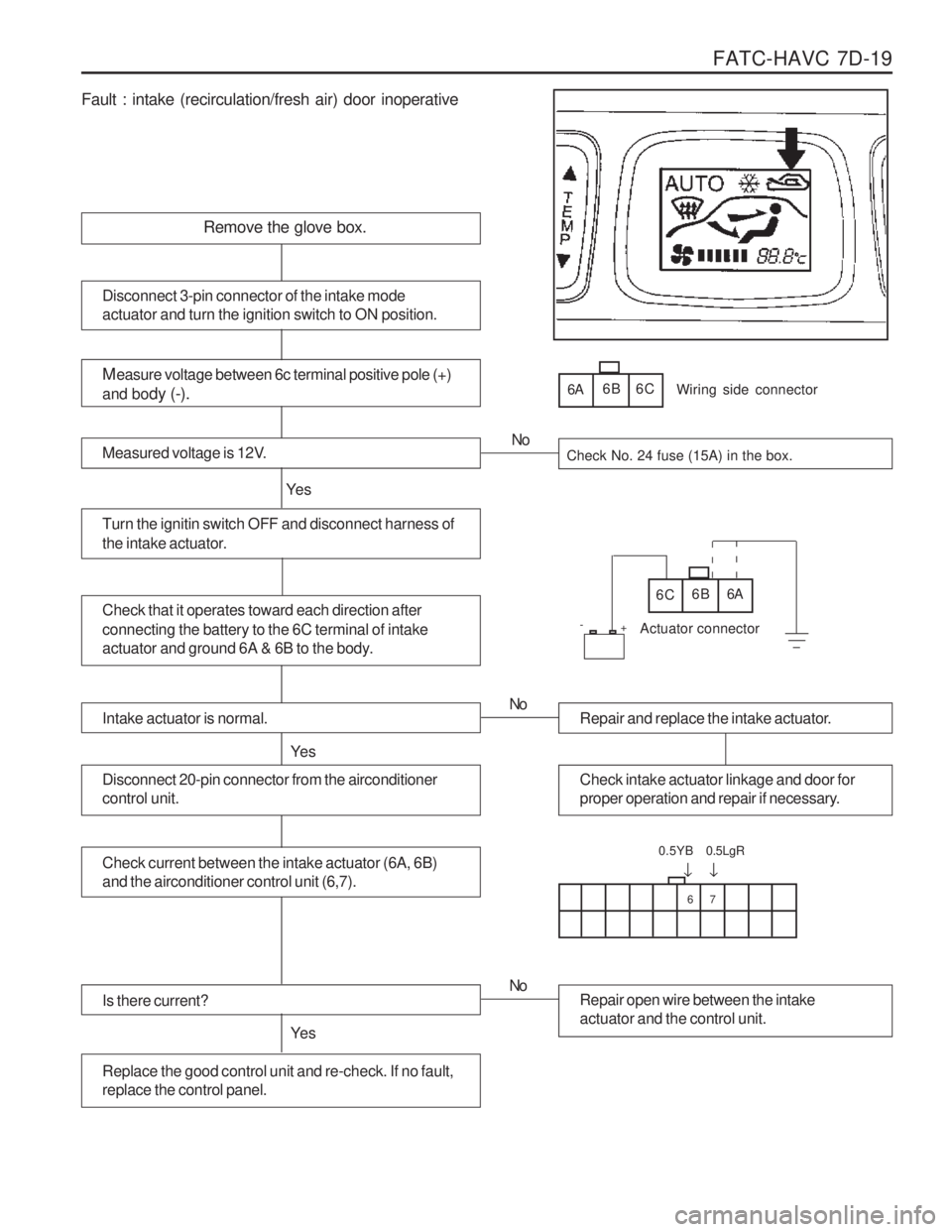
FATC-HAVC 7D-19
Fault : intake (recirculation/fresh air) door inoperative
Remove the glove box.
Measure voltage between 6c terminal positive pole (+)
and bo dy (-).
Measured voltage is 12V.Check No. 24 fuse (15A) in the box.
Turn the ignitin switch OFF and disconnect harness of
the intake actuator.
Ye s No
Disconnect 3-pin connector of the intake mode actuator and turn the ignition switch to ON position.
6A
6B 6C
Check that it operates toward each direction after connecting the battery to the 6C terminal of intake
actuator and ground 6A & 6B to the body.6C 6B 6A
Wiring side connector
Actuator connector
Intake actuator is normal.
Ye s
Repair and replace the intake actuator.
No
Check intake actuator linkage and door for
proper operation and repair if necessary.Disconnect 20-pin connector from the airconditioner control unit.
Check current between the intake actuator (6A, 6B) and the airconditioner control unit (6,7).
Is there current?
Ye s
Repair open wire between the intake actuator and the control unit.
No
Replace the good control unit and re-check. If no fault, replace the control panel.
67
�
0.5YB
�
0.5LgR
+
-
Page 1176 of 1574

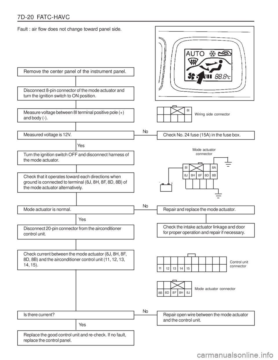
7D-20 FATC-HAVC Fault : air flow does not change toward panel side.
8H
Remove the center panel of the instrument panel.
Measure voltage between 8I terminal positive pole (+) and body (-).
Measured voltage is 12V.Check No. 24 fuse (15A) in the fuse box.
Turn the ignition switch OFF and disconnect harness of
the mode actuator.
Ye sNo
Disconnect 8-pin connector of the mode actuator and turn the ignition switch to ON position.
Check that it operates toward each directions when
ground is connected to terminal (8J, 8H, 8F, 8D, 8B) of
the mode actuator alternatively.
Mode actuator
connector
Mode actuator is normal.
Ye s
Repair and replace the mode actuator.
No
Check the intake actuator linkage and door
for proper operation and repair if necessary.Disconnect 20-pin connector from the airconditioner control unit.
Check current between the mode actuator (8J, 8H, 8F,
8D, 8B) and the airconditioner control unit (11, 12, 13,14, 15).
Is there current?
Ye s
Repair open wire between the mode actuator and the control unit.
No
Replace the good control unit and re-check. If no fault, replace the control panel.
14 15
+
-
8
IWiring side connector
8I
8J 8H 8F 8D 8B 8A
Mode actuator connector Control unit connector
12 13
11
8B 8D 8F 8J