Page 1132 of 1574
TRANSFER CASE (TOD) 5D2-43
Disassembly Procedure
1. Disconnect transfer case from vehicle
2. Using a 30mm thin-wall socket, first remove the rear outputnut, output shaft yoke washer, oil seal then the case flange.Installation Notice
27 Nut
28 Washer
30 Case Flange
Tightening Torque 137 - 196 Nm
3. Disconnect shift motor/clutch coil connector and speed sensor connector from upper bracket of transfer case. Notice
When disconnect connector, pull forwards grasping connector housing.
4. Remove outer tube on speed sensor connector.
5. Remove wire supporting cape back side of speed sensor connector.
6. Disconnect pin of clutch coil wire (yellow) from speed sensor connector (white 7 pin) using long-nose plier.
7. Remove shift motor.
Notice
When remove shift motor, pay attention to the location of
triangular slot and shaft in transfer case inside motor.
8. Disconnect front and rear speed sensor.
Page 1140 of 1574

TRANSFER CASE (TOD) 5D2-51
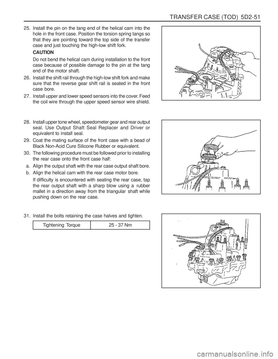
25. Install the pin on the tang end of the helical cam into thehole in the front case. Position the torsion spring tangs so that they are pointing toward the top side of the transfer case and just touching the high-low shift fork. CAUTIONDo not bend the helical cam during installation to the front case because of possible damage to the pin at the tangend of the motor shaft.
26. Install the shift rail through the high-low shift fork and make sure that the reverse gear shift rail is seated in the frontcase bore.
27. Install upper and lower speed sensors into the cover. Feed the coil wire through the upper speed sensor wire shield.
2 8. Install upper tone wheel, speedometer gear and rear output seal. Use Output Shaft Seal Replacer and Driver orequivalent to install seal.
29. Coat the mating surface of the front case with a bead of Black Non-Acid Cure Silicone Rubber or equivalent.
30. The following procedure must be followed prior to installing the rear case onto the front case half:
a. Align the output shaft with the rear case output shaft bore.
b. Align the helical cam with the rear case motor bore. If difficulty is encountered with seating the rear case, tap
the rear output shaft with a sharp blow using a rubber
mallet in a direction away from the triangular shaft whilepushing down on the rear case.
Tightening Torque 25 - 37 Nm
31. Install the bolts retaining the case halves and tighten.
Page 1142 of 1574
TRANSFER CASE (TOD) 5D2-53
40. Install the rear case flange on the output shaft. Install therubber seal, output shaft yoke washer and nut. Tighten the nut.
Tightening Torque 137 - 196 Nm
41. Install the drainplug and tighten.
42. Fill the transfer case with 1.4 liters of Automatic Transmission Fluid or equivalent. NoticeFluid level should be just below the filler plug hole.
Tightening Torque 19 - 30 Nm
Tightening Torque 19 - 30 Nm
43. Install the fill pulg and tighten.
44. Install the transfer case as outlined in removal and
Installation, transfer case in the section. NoticeMake sure proper drain and fill plugs are installed if case is replaced.
Page 1150 of 1574
6A-8 POWER STEERING SYSTEM
Tightening Torque 35 - 45 Nm
Removal & Installation Procedure
1. Remove the cotter pin and nut and separate the steering
gear box tie rod from the steering knuckle arm using the
puller. Installation Notice
2. Remove the bolt and separate the lower sha from the steering gear box. Installation Notice
Tightening Torque 30 - 40 Nm
3. Remove the oil pipe from the steering gear box and drain the oil. Installation Notice
4. Remove the clamp bolts and remove the steering gear box assembly. Installation Notice
Tightening Torque 12 - 18 Nm
Notice
� Be careful not to damage the rubber(1).
� When installing tighten the bolt (3) with the rubber
(2)being inserted to the hole of clamp.
5. Bleed the air from system.
6. Check the toe-in.
Tightening Torque 70 - 90 Nm
Tighten the bolt toward threadless side of lower shaft coupling.
Page 1151 of 1574
POWER STEERING SYSTEM 6A-9
Inspection Procedure
1. Check the distance of tie rod and toe-in data and, ifnecessary, adjust as below.
2. Adjustment � Unscrew the adjuster nut (1) and adjust the distance by
turning the rod (2) counterclockwise.
Distance of Tie Rod 152mm
Toe-in 0 - 4 mm
Tightening Torque 65 - 80Nm
�
Check the toe-in date (A~B)
� If the ton-in is normal, tighten the adjuster nut (1) to the
specified toque with tie rod (2) being fixed. Tightening
Page 1154 of 1574
STEERING WHEEL AND COLUMN 6E-3
Removal & Installation Procedure
1. Remove the horn pad from the steering wheel anddisconnect the connectors .
2. Place an alignment marks on the column shaft end and fixing nut and then remove the fixing nut. Installation Notice
3. Remove the steering wheel.
4. Remove the combination switch upper cover .
Tightening Torque 50 - 80 Nm
5. Release the crash pad panel. Notice Remove the hood release wire and the other switch connectors.
Page 1155 of 1574
6E-4 STEERING WHEEL AND COLUMN
6. Disconnect each connectors.
7. Remove the vacuum hose from the ignition switch(Dieselonly) .
9. Remove the lower shaft by removing the bolt of the steering column shaft. Installation Notice
Tightening Torque 9 - 14 Nm
8. Remove the combination switch assembly.
10. Remove the dash panel mounting bolts. Installation Notice
Tightening Torque 30 - 40 Nm
Page 1156 of 1574
STEERING WHEEL AND COLUMN 6E-5
Tightening Torque 30 - 40 Nm
11. Remove the steering column upper mounting bolt and pull
out steering column assembly. Installation Notice
12. Installation is reverse order of the removal.