Page 1064 of 1574
5D1-12 TRANSFER CASE (PART TIME 4408)
Removal & Installation Procedure
1. Disconnect the negative terminal from the battery.
2. Lift up the vehicle and fix it safely.
3. Remove the drain plug and drain the oil.Reinstall the drain plug.
* If planar damper is installed, unscrew 4 bolts and remove the planar damper.
Installation Notice
Tightening Torque 19 - 30 Nm
4. Remove the breather hose.
5. Disconnect the speedometer cable connector and other cable connectors and wiring harnesses.
6. Support the transfer case with jack and remove the front and rear propeller shafts from the transfer case. Installation Notice
Front
Rear 81 - 89 Nm 70 - 80 NmTightening Torque
Page 1067 of 1574

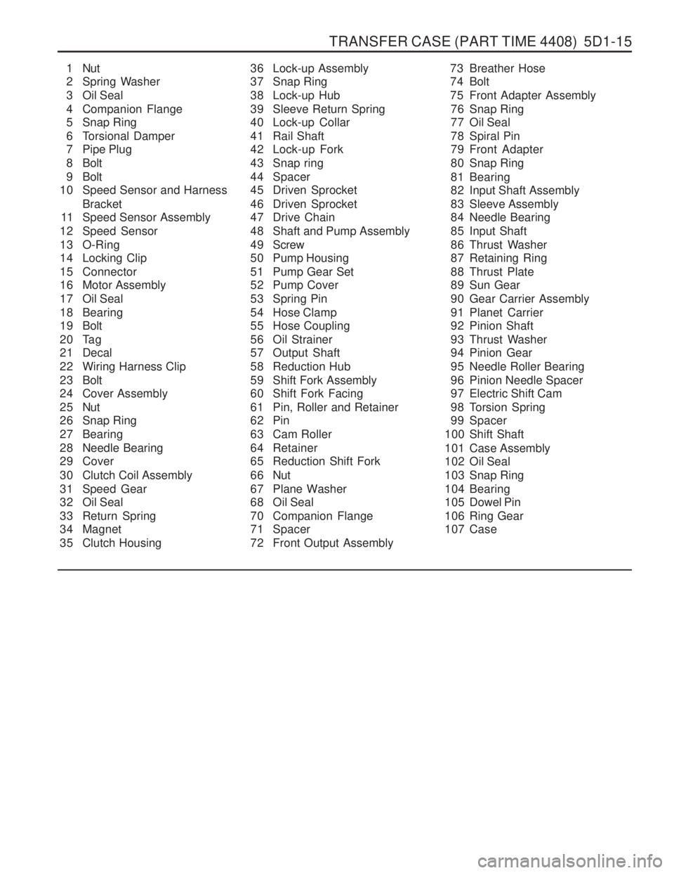
TRANSFER CASE (PART TIME 4408) 5D1-15
1 Nut
2 Spring Washer
3 Oil Seal
4 Companion Flange
5 Snap Ring
6 Torsional Damper
7 Pipe Plug
8 Bolt
9 Bolt
10 Speed Sensor and Harness
Bracket
11 Speed Sensor Assembly
12 Speed Sensor
13 O-Ring
14 Locking Clip
15 Connector
16 Motor Assembly
17 Oil Seal
18 Bearing
19 Bolt
20 Tag
21 Decal
22 Wiring Harness Clip
23 Bolt
24 Cover Assembly
25 Nut
26 Snap Ring
27 Bearing
28 Needle Bearing
29 Cover
30 Clutch Coil Assembly
31 Speed Gear
32 Oil Seal
33 Return Spring
34 Magnet
35 Clutch Housing 36 Lock-up Assembly
37 Snap Ring
38 Lock-up Hub
39 Sleeve Return Spring
40 Lock-up Collar
41 Rail Shaft
42 Lock-up Fork
43 Snap ring
44 Spacer
45 Driven Sprocket
46 Driven Sprocket
47 Drive Chain
48 Shaft and Pump Assembly
49 Screw
50 Pump Housing
51 Pump Gear Set
52 Pump Cover
53 Spring Pin
54 Hose Clamp
55 Hose Coupling
56 Oil Strainer
57 Output Shaft
58 Reduction Hub
59 Shift Fork Assembly
60 Shift Fork Facing
61 Pin, Roller and Retainer
62 Pin
63 Cam Roller
64 Retainer
65 Reduction Shift Fork
66 Nut
67 Plane Washer
68 Oil Seal
70 Companion Flange
71 Spacer
72 Front Output Assembly 73 Breather Hose
74 Bolt
75 Front Adapter Assembly
76 Snap Ring
77 Oil Seal
78 Spiral Pin
79 Front Adapter
80 Snap Ring
81 Bearing
82 Input Shaft Assembly
83 Sleeve Assembly
84 Needle Bearing
85 Input Shaft
86 Thrust Washer
87 Retaining Ring
88 Thrust Plate
89 Sun Gear
90 Gear Carrier Assembly
91 Planet Carrier
92 Pinion Shaft
93 Thrust Washer
94 Pinion Gear
95 Needle Roller Bearing
96 Pinion Needle Spacer
97 Electric Shift Cam
98 Torsion Spring
99 Spacer
100 Shift Shaft
101 Case Assembly
102 Oil Seal
103 Snap Ring
104 Bearing
105 Dowel Pin
106 Ring Gear
107 Case
Page 1068 of 1574
5D1-16 TRANSFER CASE (PART TIME 4408)
Disassembly Procedure
1. Holding the companion flange, remove the nut and washerand then remove the companion flange and oil seal.
2. Remove the 2 plugs from the cover.
1 Nut
2 Washer
3 Oil Seal
4 Companion Flange
5 Plug
2 5 Cover
6 Bolt
7 Washer
8 Bolt
9 Sensor and Harness Bracket
10 Sensor Assembly 11 Speed Sensor
12 O-ring
13 Motor Assembly
2 5 Cover
1. Remove the bolt, washer,3 bolts and harness bracket.
2. Remove the sensor assembly and remove the O-ring from
the speed sensor.
3. Remove the motor assembly.
Page 1069 of 1574

TRANSFER CASE (PART TIME 4408) 5D1-17
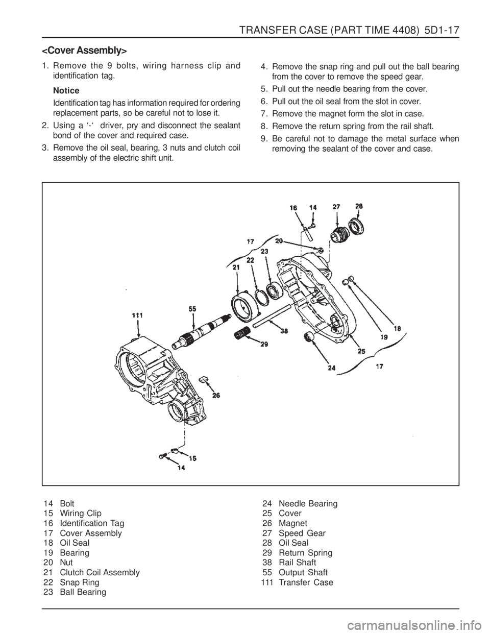
1. Remove the 9 bolts, wiring harness clip andidentification tag. Notice Identification tag has information required for ordering replacement parts, so be careful not to lose it.
2. Using a ‘-‘ driver, pry and disconnect the sealant
bond of the cover and required case.
3. Remove the oil seal, bearing, 3 nuts and clutch coil assembly of the electric shift unit.
14 Bolt
15 Wiring Clip
16 Identification Tag
17 Cover Assembly
18 Oil Seal
19 Bearing
20 Nut
21 Clutch Coil Assembly
22 Snap Ring
23 Ball Bearing 4. Remove the snap ring and pull out the ball bearing
from the cover to remove the speed gear.
5. Pull out the needle bearing from the cover.
6. Pull out the oil seal from the slot in cover.
7. Remove the magnet form the slot in case.
8. Remove the return spring from the rail shaft.
9. Be careful not to damage the metal surface when removing the sealant of the cover and case.
24 Needle Bearing
25 Cover
26 Magnet
27 Speed Gear
28 Oil Seal
29 Return Spring
38 Rail Shaft
55 Output Shaft
111 Transfer Case
Page 1071 of 1574
TRANSFER CASE (PART TIME 4408) 5D1-19
1. Holding the companion flange, remove the nut and washerand then remove the companion flange and oil seal.
2. Remove the output shaft.
65 Nut
66 Washer
67 Oil Seal
70 Companion Flange
71 Output Shaft (front)
111 Case
57 Reduction Hub
58 Shift Fork Facing
59 Reduction Shift Fork Assembly
60 Roller Pin and Retainer Assembly
61 Retainer
62 Pin
63 Roller Cam
64 Reduction Shift Fork
1. Remove the reduction hub and reduction shift fork assembly
from the case.
2. Remove the 2 shill fork facings from the shift fork assembly.
3. To remove the roller cam and pin, cut elf the plastic retainer when disassembling the fork assembly.
Page 1072 of 1574

5D1-20 TRANSFER CASE (PART TIME 4408)
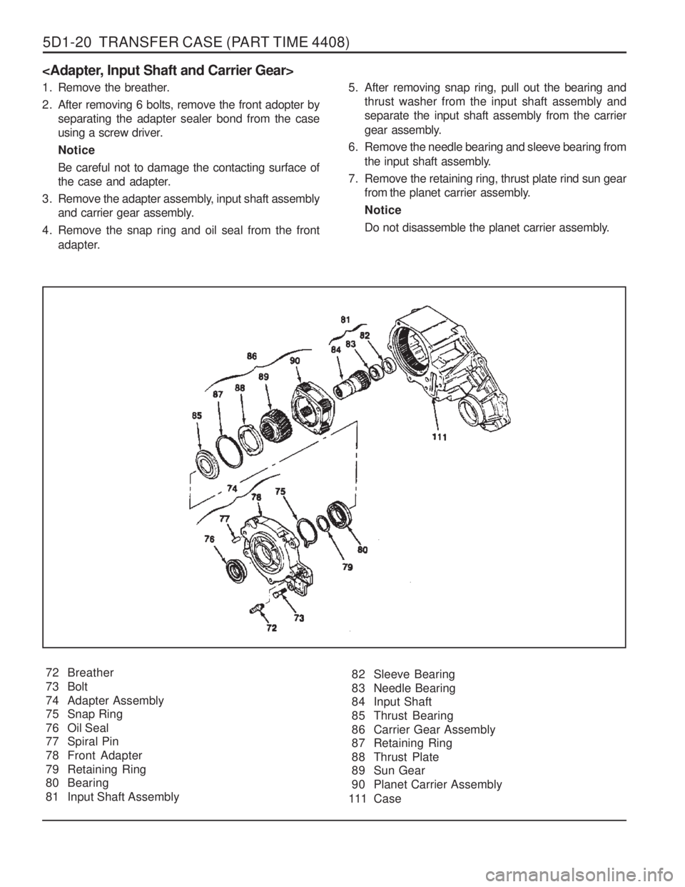
72 Breather
73 Bolt
74 Adapter Assembly
75 Snap Ring
76 Oil Seal
77 Spiral Pin
78 Front Adapter
79 Retaining Ring
80 Bearing
81 Input Shaft Assembly
1. Remove the breather.
2. After removing 6 bolts, remove the front adopter by separating the adapter sealer bond from the case
using a screw driver. NoticeBe careful not to damage the contacting surface of
the case and adapter.
3. Remove the adapter assembly, input shaft assembly and carrier gear assembly.
4. Remove the snap ring and oil seal from the front adapter. 5. After removing snap ring, pull out the bearing and
thrust washer from the input shaft assembly andseparate the input shaft assembly from the carrier
gear assembly.
6. Remove the needle bearing and sleeve bearing from the input shaft assembly.
7. Remove the retaining ring, thrust plate rind sun gear from the planet carrier assembly. Notice
Do not disassemble the planet carrier assembly.
82 Sleeve Bearing
83 Needle Bearing
84 Input Shaft
85 Thrust Bearing
86 Carrier Gear Assembly
87 Retaining Ring
88 Thrust Plate
89 Sun Gear
90 Planet Carrier Assembly
111 Case
Page 1073 of 1574
TRANSFER CASE (PART TIME 4408) 5D1-21
1. Remove the electric shift cam parts from the case assembly.
2. Separate the electric shift cam from the shift shaft.
3. Holding the shift shaft in a vise, remove the torsion springand spacer from the shift shaft using a screw driver.
100 Electric Shift Cam
101 Torsion Spring
102 Spacer
103 Shift Shaft
111 Case
105 Transfer Case Assembly
106 Oil Seal
107 Retaining Ring
108 Ball Bearing
119 Pin
110 Ring Gear
111 Case
1. Remove the oil seal.
2. Remove the retaining ring and bearing.
3. Remove the pin from the transfer case.
Notice Be careful not to damage the pin.
4. Using a press, remove the ring gear from the case.
Page 1074 of 1574

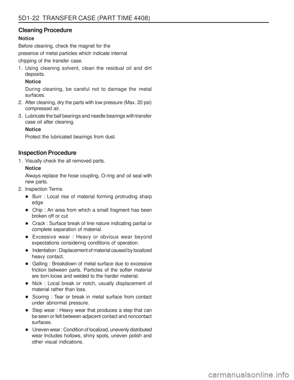
5D1-22 TRANSFER CASE (PART TIME 4408) Cleaning Procedure Notice Before cleaning, check the magnet for thepresence of metal particles which indicate internalchipping of the transfer case.
1. Using cleaning solvent, clean the residual oil and dirtdeposits.Notice
During cleaning, be careful not to damage the metal surfaces.
2. After cleaning, dry the parts with low pressure (Max. 20 psi) compressed air.
3. Lubricate the ball bearings and needle bearings with transfer case oil after cleaning. NoticeProtect the lubricated bearings from dust.
Inspection Procedure
1. Visually check the all removed parts. Notice
Always replace the hose coupling, O-ring and oil seal with new parts.
2. Inspection Terms � Burr : Local rise of material forming protruding sharp
edge
� Chip : An area from which a small fragment has been
broken off or cut
� Crack : Surface break of line nature indicating partial or
complete separation of material.
� Excessive wear : Heavy or obvious wear beyond
expectations considering conditions of operation.
� Indentation : Displacement of material caused by localized
heavy contact.
� Galling : Breakdown of metal surface due to excessive
friction between parts. Particles of the softer materialare torn loose and welded to the harder material.
� Nick : Local break or notch, usually displacement of
material rather than loss.
� Scoring : Tear or break in metal surface from contact
under abnormal pressure.
� Step wear : Heavy wear that produces a step that can
be seen or felt between adjacent contact and noncontactsurfaces.
� Uneven wear : Condition of localized, unevenly distributed
wear Includes hollows, shiny spots, uneven polish and other visual indications.