Page 1201 of 1574

SUPPLEMENTAL RESTRAINT SYSTEM(SRS) 8B-21
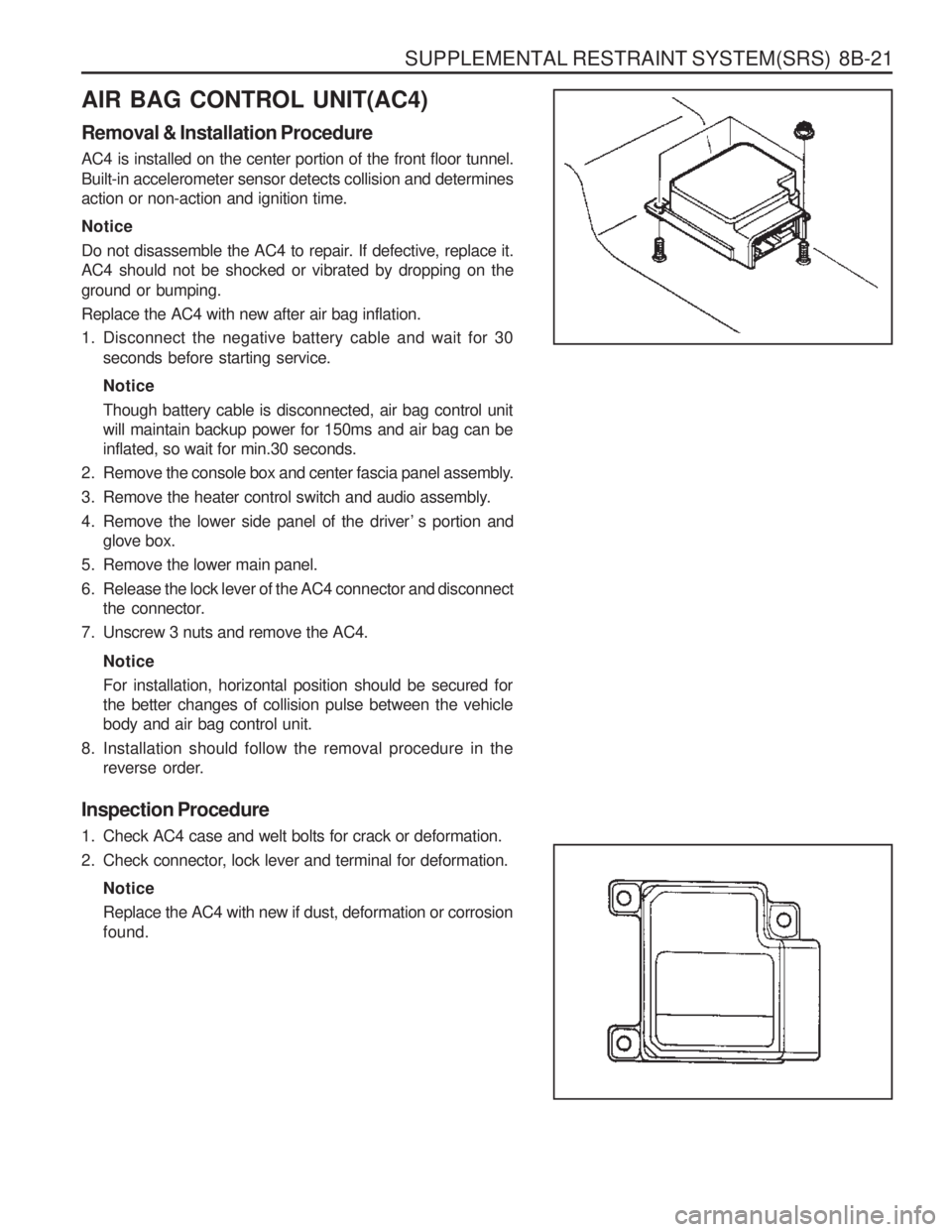
AIR BAG CONTROL UNIT(AC4) Removal & Installation Procedure AC4 is installed on the center portion of the front floor tunnel.
Built-in accelerometer sensor detects collision and determines action or non-action and ignition time. Notice
Do not disassemble the AC4 to repair. If defective, replace it. AC4 should not be shocked or vibrated by dropping on the ground or bumping. Replace the AC4 with new after air bag inflation.
1. Disconnect the negative battery cable and wait for 30seconds before starting service. Notice Though battery cable is disconnected, air bag control unit will maintain backup power for 150ms and air bag can beinflated, so wait for min.30 seconds.
2. Remove the console box and center fascia panel assembly.
3. Remove the heater control switch and audio assembly.
4. Remove the lower side panel of the driver ’ s portion and glove box.
5. Remove the lower main panel.
6. Release the lock lever of the AC4 connector and disconnect the connector.
7. Unscrew 3 nuts and remove the AC4.
NoticeFor installation, horizontal position should be secured for the better changes of collision pulse between the vehiclebody and air bag control unit.
8. Installation should follow the removal procedure in the reverse order.
Inspection Procedure
1. Check AC4 case and welt bolts for crack or deformation.
2. Check connector, lock lever and terminal for deformation. NoticeReplace the AC4 with new if dust, deformation or corrosion found.
Page 1305 of 1574

SECTION 9T
REMOTE KEYLESS ENTRY ANDANTI-THEFT SYSTEM
Caution: Disconnect the negative battery cable before removing or installing any electrical unit or when a tool or equipment could easily come in contact with exposed electrical terminals. Disconnecting this cablewill help prevent personal injury and damage to the vehicle. The ignition must also be in LOCK unless otherwisenoted.
TABLE OF CONTENTS
Specifications . . . . . . . . . . . . . . . . . . . . . . . . 9T-1
REKES Specifications . . . . . . . . . . . . . . . . . . . 9T-1
Schematic and Routing Diagrams . . . . . . . . 9T-2
REKES . . . . . . . . . . . . . . . . . . . . . . . . . . . . . . 9T-2
Diagnosis . . . . . . . . . . . . . . . . . . . . . . . . . . . 9T-3
SPECIFICATIONS
REKES SPECIFICATIONS Diagnosis Test . . . . . . . . . . . . . . . . . . . . . . . .
9T-3
Maintenance and Repair . . . . . . . . . . . . . . . 9T-5
On-Vehicle Service . . . . . . . . . . . . . . . . . . . . . . 9T-5
REKES . . . . . . . . . . . . . . . . . . . . . . . . . . . . . . 9T-5
Transmitter
Description DC 3V
-10 °C - 60 °C
Changeable Coin Type LITHIUM Battery (CR2032)
Above 2 years (10 times/day)
Application
Rated Voltage
Rated Range of Operating Temperature Model Durability
Description DC 12V
DC 8V - 16V
-30 °C - +80 °C
Above 5M �
Maximum 3mA
Application
Rated Voltage
Rated Range of Operating Voltage
Rated Range of Operating Temperature Insulating Resistance Arm Current
Receiver
Page 1308 of 1574

CONTROL UNITS AND SYSTEM 9U-3
FUNCTION DESCRIPTION
STICS Operating Functions
NO.Application Deseription
1 Wiper INT sensing vehicle speed �By operating INT time control volume, variable time will be changed within 1.5 - 20 seconds.
2 Washer relating wiper �Wiper begins to operate within 0.6 - 1 sec when the washer switch is ON and it operates 3 times after the washer switch is OFF while the IGN2 switch in ON.
3 Dimming room lamp
�When room lamp is coupled with door, it turns on if door is opened. After closing the door it maintains 2 seconds of lightingand dims off whithin 3 seconds.
4 Time delayed power window control �Power window can be operated within 30 seconds after turning
the IGN1 switch from ON to OFF. If driver ’s/passenger ’s door is
opened within the 30 seconds, time will be prolonged for more 30 seconds from that moment.
5 Rear defogger timer �The rear defogger will be operated for 12 min. by turning ON the defogger switch while engine is running.
� Defogger will be stopped by pushing the switch again.
� The defogger will be operated 6 min, if push ON the switch within10 min. after 12 min. of operation.
6
Seat belt warning �The warning lamp will be turned on for about 6 sec. with an intermittent chime bell when the IGN. switch is ON unlessfastening the seat belt.
7 Parking brake warning
�The indicator lamp will flash if drive while the parking brake is applied.
8 Tail lamp lighting warning �When the driver ’s door is opened while the tail lamp is still ON,
the buzzer operates intermittently. In this condition, the door will be automatically unlocked when it locked.
9 Door ajar warning
�The indicator lamp will be blinking when the door is not closed completely and driving.
10 IGN key reminder
�The chime will be operated intermittently if the driver ’s door is
opened while the IGN key is still remaining in the ignition switch. In this condition, the door will be automatically unlocked when itlocked.
11 Central door lock �All doors will be locked/unlocked by locking/unlocking the driver ’s or passenger ’s door.