2003 SSANGYONG MUSSO warning
[x] Cancel search: warningPage 1194 of 1574
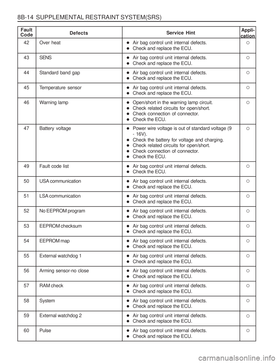
8B-14 SUPPLEMENTAL RESTRAINT SYSTEM(SRS)
Fault
CodeDefects Service HintAppli-
cation
42 Over heat
4 3 SENS
44 Standard band gap
45 Temperature sensor
46 Warning lamp
47 Battery voltage
49 Fault code list
5 0 USA communication
51 LSA communication
52 No EEPROM program
53 EEPROM checksum
5 4 EEPROM map
55 External watchdog 1
� Air bag control unit internal defects.
� Check and replace the ECU.
� Air bag control unit internal defects.
� Check and replace the ECU.
� Air bag control unit internal defects.
� Check and replace the ECU.
� Air bag control unit internal defects.
� Check and replace the ECU.
� Open/short in the warning lamp circuit.
� Check related circuits for open/short.
� Check connection of connector.
� Check the ECU.
� Power wire voltage is out of standard voltage (9 - 16V).
� Check the battery for voltage and charging.
� Check related circuits for open/short.
� Check connection of connector.
� Check the ECU.
� Air bag control unit internal defects.
� Check the ECU.
� Air bag control unit internal defects.
� Check and replace the ECU.
� Air bag control unit internal defects.
� Check and replace the ECU.
� Air bag control unit internal defects.
� Check and replace the ECU.
� Air bag control unit internal defects.
� Check and replace the ECU.
� Air bag control unit internal defects.
� Check and replace the ECU.
� Air bag control unit internal defects.
� Check and replace the ECU.
56 Arming sensor-no close
57 RAM check
5 8 System
�Air bag control unit internal defects.
� Check and replace the ECU.
� Air bag control unit internal defects.
� Check and replace the ECU.
� Air bag control unit internal defects.
� Check and replace the ECU.
59 External watchdog 2
60 Pulse
�Air bag control unit internal defects.
� Check and replace the ECU.
� Air bag control unit internal defects.
� Check and replace the ECU.
Page 1202 of 1574
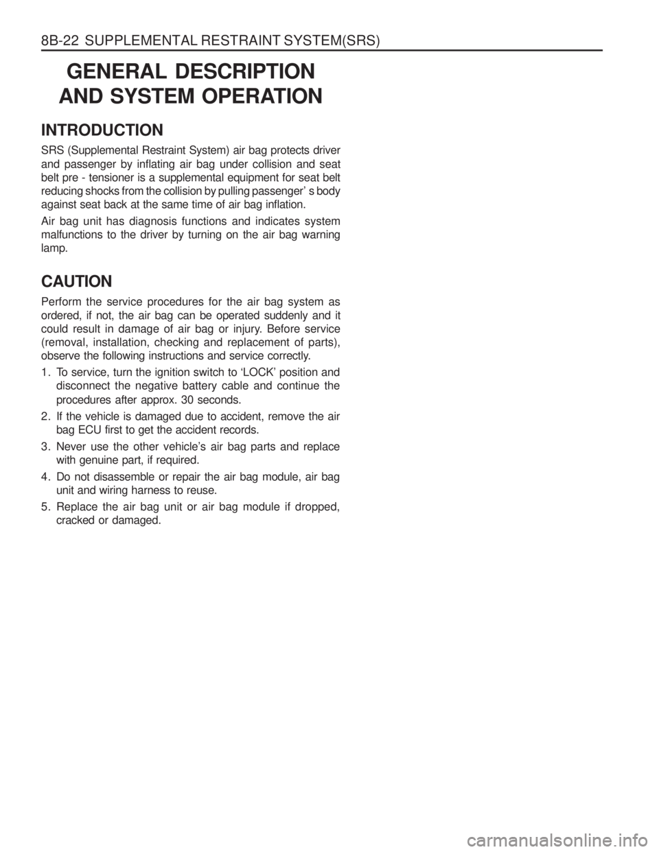
8B-22 SUPPLEMENTAL RESTRAINT SYSTEM(SRS)GENERAL DESCRIPTION
AND SYSTEM OPERATION
INTRODUCTION SRS (Supplemental Restraint System) air bag protects driver and passenger by inflating air bag under collision and seat belt pre - tensioner is a supplemental equipment for seat belt
reducing shocks from the collision by pulling passenger’ s bodyagainst seat back at the same time of air bag inflation. Air bag unit has diagnosis functions and indicates system malfunctions to the driver by turning on the air bag warninglamp. CAUTION Perform the service procedures for the air bag system as ordered, if not, the air bag can be operated suddenly and it
could result in damage of air bag or injury. Before service(removal, installation, checking and replacement of parts),
observe the following instructions and service correctly.
1. To service, turn the ignition switch to ‘LOCK’ position and disconnect the negative battery cable and continue the procedures after approx. 30 seconds.
2. If the vehicle is damaged due to accident, remove the air bag ECU first to get the accident records.
3. Never use the other vehicle’s air bag parts and replace with genuine part, if required.
4. Do not disassemble or repair the air bag module, air bag unit and wiring harness to reuse.
5. Replace the air bag unit or air bag module if dropped, cracked or damaged.
Page 1208 of 1574
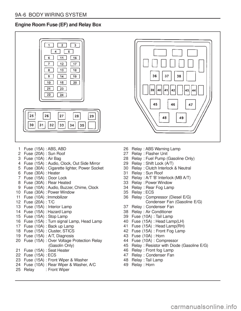
9A-6 BODY WIRING SYSTEM Engine Room Fuse (EF) and Relay Box1 Fuse (15A) : ABS, ABD
2 Fuse (20A) : Sun Roof
3 Fuse (10A) : Air Bag
4 Fuse (15A) : Audio, Clock, Out Side Mirror
5 Fuse (30A) : Cigarette lighter, Power Socket
6 Fuse (30A) : Heater
7 Fuse (15A) : Door Lock
8 Fuse (30A) : Rear Heated
9 Fuse (10A) : Audio, Buzzer, Chime, Clock
10 Fuse (30A) : Power Window
11 Fuse (10A) : Immobilizer
12 Fuse (20A) : T/C
13 Fuse (15A) : Interior Lamp
14 Fuse (15A) : Hazard Lamp
15 Fuse (15A) : Stop Lamp
16 Fuse (15A) : Turn signal Lamp, Head Lamp
17 Fuse (10A) : Back up Lamp
18 Fuse (15A) : Cluster, STICS
19 Fuse (15A) : A/T, Diagnosis
20 Fuse (15A) : Over Voltage Protection Relay (Gasolin Only)
21 Fuse (15A) : Seat Heater
22 Fuse (15A) : ECS
23 Fuse (15A) : Front Wiper & Washer
24 Fuse (10A) : Rear Wiper & Washer, A/C
25 Relay : Front Wiper 26 Relay : ABS Warning Lamp
27 Relay : Flasher Unit
28 Relay : Fuel Pump (Gasoline Only)
29 Relay : Shift Lock (A/T)
30 Relay : Clutch Interlock & Neutral
31 Relay : Sun Roof
32 Relay : A/T ‘B’ Interlock (MB A/T)
33 Relay : Power Window
34 Relay : Rear Fog Lamp
35 Relay : ECS
36 Relay : Compressor (Diesel E/G)
Condenser Fan (Gasoline E/G)
37 Relay : Condenser Fan
38 Relay : Air Conditioner
39 Fuse (10A) : Tail Lamp
40 Fuse (15A) : Head Lamp(LH)
41 Fuse (15A) : Head Lamp(RH)
42 Fuse (15A) : Front Fog Lamp
43 Fuse (10A) : Horn
44 Fuse (10A) : Compressor
45 Relay : Resistor with Diode (Gasoline E/G)
46 Relay : Front fog Lamp
47 Relay : Condenser Fan
48 Relay : Tail Lamp
49 Relay : Horn
Page 1210 of 1574
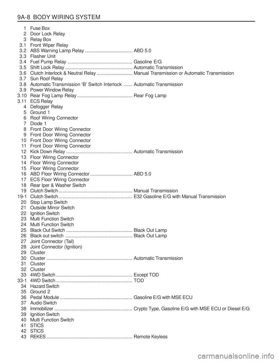
9A-8 BODY WIRING SYSTEM1 Fuse Box
2 Door Lock Relay
3 Relay Box
3.1 Front Wiper Relay
3.2 ABS Warning Lamp Relay ....................................ABD 5.0
3.3 Flasher Unit
3.4 Fuel Pump Relay ................................................. Gasoline E/G
3.5 Shift Lock Relay ................................................... Automatic Transmission
3.6 Clutch Interlock & Neutral Relay ...........................Manual Transmission or Automatic Transmission
3.7 Sun Roof Relay
3.8 Automatic T ransmission ‘B’ Switch Interlock ....... Automatic Transmission
3.9 Power Window Relay
3.10 Rear Fog Lamp Relay .......................................... Rear Fog Lamp
3.11 ECS Relay 4 Defogger Relay
5 Ground 1
6 Roof Wiring Connector
7 Diode 1
8 Front Door Wiring Connector
9 Front Door Wiring Connector
10 Front Door Wiring Connector 11 Front Door Wiring Connector
12 Kick Down Relay .................................................. Automatic Transmission
13 Floor Wiring Connector
14 Floor Wiring Connector
15 Floor Wiring Connector
16 ABD Floor Wiring Connector ................................ABD 5.0
17 ECS Floor Wiring Connector
18 Rear Iper & Washer Switch
19 Clutch Switch ........................................................ Manual Transmission
19-1 Clutch Switch ........................................................ E32 Gasoline E/G with Manual Transmission
20 Stop Lamp Switch
21 Outside Mirror Switch
22 Ignition Switch
23 Multi Function Switch
24 Multi Function Switch
25 Black Out Switch .................................................. Black Out Lamp
26 Black out switch ................................................... Black Out Lamp
27 Joint Connector (Tail)
28 Joint Connector (Ignition)
29 Cluster
30 Cluster ................................................................. Automatic Transmission
31 Cluster
32 Cluster
33 4WD Switch .......................................................... Except TOD
33-1 4WD Switch .......................................................... TOD
3 4 Hazard Switch
35 Ground 2
36 Pedal Module ....................................................... Gasoline E/G with MSE ECU
37 Audio Switch
3 8 Immobilizer ........................................................... Crypto Type, Gasoline E/G with MSE ECU or Diesel E/G
39 Ignition Switch
40 Multi Function Switch
4 1 STICS
4 2 STICS
4 3 REKES ................................................................. Remote Keyless
Page 1252 of 1574
INSTRUMENTATION/DRIVER INFORMATION 9E-3
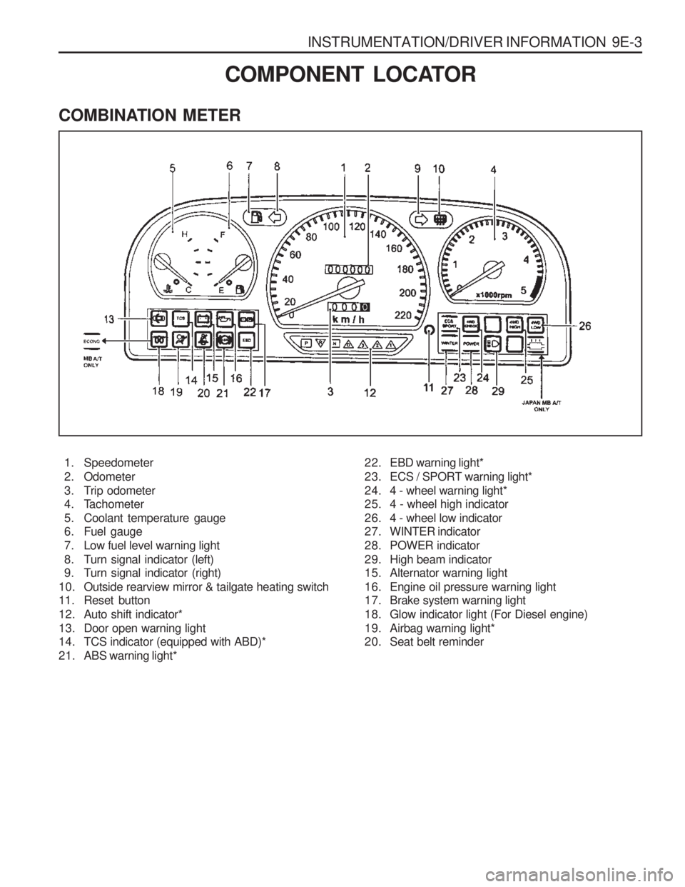
COMBINATION METER
COMPONENT LOCATOR
1. Speedometer
2. Odometer
3. Trip odometer
4. Tachometer
5. Coolant temperature gauge
6. Fuel gauge
7. Low fuel level warning light
8. Turn signal indicator (left)
9. Turn signal indicator (right)
10. Outside rearview mirror & tailgate heating switch
11. Reset button
12. Auto shift indicator*
13. Door open warning light
14. TCS indicator (equipped with ABD)*
21. ABS warning light* 22. EBD warning light*
23. ECS / SPORT warning light*
24. 4 - wheel warning light*
25. 4 - wheel high indicator
26. 4 - wheel low indicator
27. WINTER indicator
28. POWER indicator
29. High beam indicator
15. Alternator warning light
16. Engine oil pressure warning light
17. Brake system warning light
18. Glow indicator light (For Diesel engine)
19. Airbag warning light*
20. Seat belt reminder
Page 1306 of 1574
9U-10 CONTROL UNITS AND SYSTEMMAINTENANCE AND REPAIR
ON-VEHICLE SERVICE
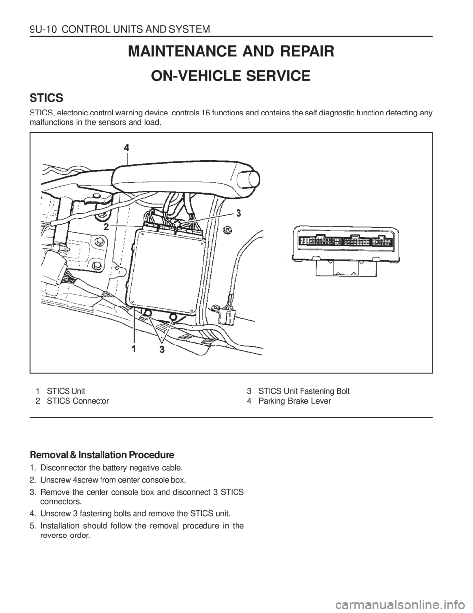
STICS STICS, electonic control warning device, controls 16 functions and contains the self diagnostic function detecting any malfunctions in the sensors and load. Removal & Installation Procedure
1. Disconnector the battery negative cable.
2. Unscrew 4screw from center console box.
3. Remove the center console box and disconnect 3 STICS connectors.
4. Unscrew 3 fastening bolts and remove the STICS unit.
5. Installation should follow the removal procedure in the reverse order.
1 STICS Unit
2 STICS Connector 3 STICS Unit Fastening Bolt
4 Parking Brake Lever
Page 1308 of 1574
CONTROL UNITS AND SYSTEM 9U-3
FUNCTION DESCRIPTION
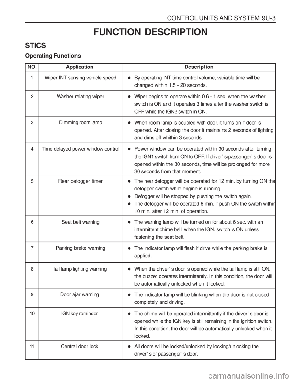
STICS Operating Functions
NO.Application Deseription
1 Wiper INT sensing vehicle speed �By operating INT time control volume, variable time will be changed within 1.5 - 20 seconds.
2 Washer relating wiper �Wiper begins to operate within 0.6 - 1 sec when the washer switch is ON and it operates 3 times after the washer switch is OFF while the IGN2 switch in ON.
3 Dimming room lamp
�When room lamp is coupled with door, it turns on if door is opened. After closing the door it maintains 2 seconds of lightingand dims off whithin 3 seconds.
4 Time delayed power window control �Power window can be operated within 30 seconds after turning
the IGN1 switch from ON to OFF. If driver ’s/passenger ’s door is
opened within the 30 seconds, time will be prolonged for more 30 seconds from that moment.
5 Rear defogger timer �The rear defogger will be operated for 12 min. by turning ON the defogger switch while engine is running.
� Defogger will be stopped by pushing the switch again.
� The defogger will be operated 6 min, if push ON the switch within10 min. after 12 min. of operation.
6
Seat belt warning �The warning lamp will be turned on for about 6 sec. with an intermittent chime bell when the IGN. switch is ON unlessfastening the seat belt.
7 Parking brake warning
�The indicator lamp will flash if drive while the parking brake is applied.
8 Tail lamp lighting warning �When the driver ’s door is opened while the tail lamp is still ON,
the buzzer operates intermittently. In this condition, the door will be automatically unlocked when it locked.
9 Door ajar warning
�The indicator lamp will be blinking when the door is not closed completely and driving.
10 IGN key reminder
�The chime will be operated intermittently if the driver ’s door is
opened while the IGN key is still remaining in the ignition switch. In this condition, the door will be automatically unlocked when itlocked.
11 Central door lock �All doors will be locked/unlocked by locking/unlocking the driver ’s or passenger ’s door.
Page 1311 of 1574
9U-6 CONTROL UNITS AND SYSTEM
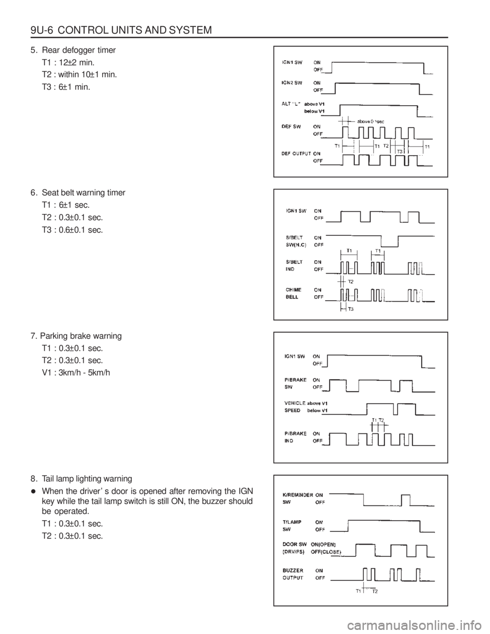
5. Rear defogger timerT1 : 12±2 min.
T2 : within 10±1 min.
T3 : 6±1 min.
6. Seat belt warning timer T1 : 6±1 sec.
T2 : 0.3±0.1 sec.
T3 : 0.6±0.1 sec.
7. Parking brake warning T1 : 0.3±0.1 sec.
T2 : 0.3±0.1 sec. V1 : 3km/h - 5km/h
8. Tail lamp lighting warning
� When the driver ’s door is opened after removing the IGN
key while the tail lamp switch is still ON, the buzzer should be operated.
T1 : 0.3±0.1 sec.
T2 : 0.3±0.1 sec.