Page 719 of 1574

WHEEL ALIGNMENT 2B-9
GENERAL DESCRIPTION AND SYSTEM OPERATION
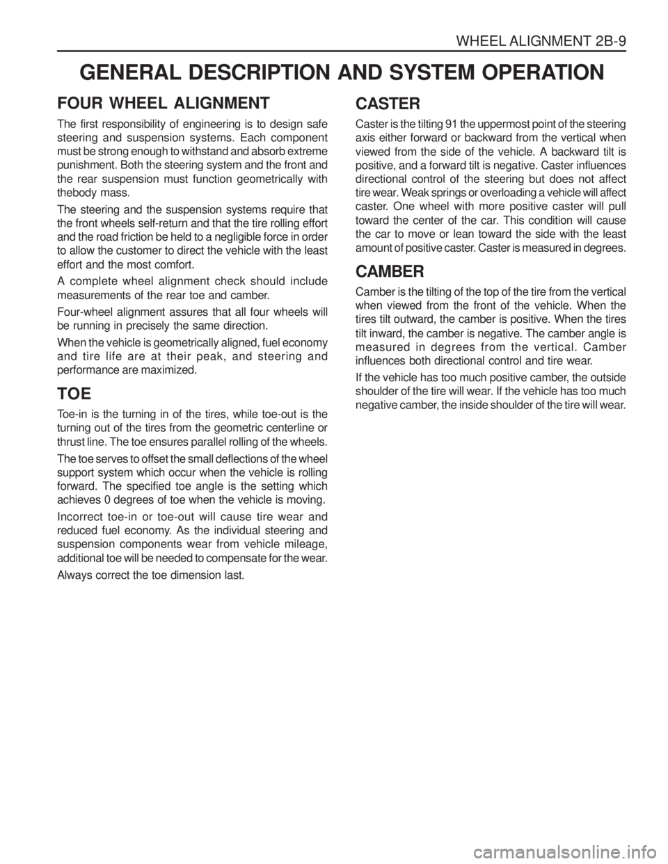
FOUR WHEEL ALIGNMENT CASTER Caster is the tilting 91 the uppermost point of the steering axis either forward or backward from the vertical when viewed from the side of the vehicle. A backward tilt is positive, and a forward tilt is negative. Caster influencesdirectional control of the steering but does not affect
tire wear. Weak springs or overloading a vehicle will affect
caster. One wheel with more positive caster will pull
toward the center of the car. This condition will cause the car to move or lean toward the side with the least
amount of positive caster. Caster is measured in degrees. CAMBER Camber is the tilting of the top of the tire from the vertical when viewed from the front of the vehicle. When thetires tilt outward, the camber is positive. When the tires tilt inward, the camber is negative. The camber angle is measured in degrees from the vertical. Camber
influences both directional control and tire wear.
If the vehicle has too much positive camber, the outside
shoulder of the tire will wear. If the vehicle has too much
negative camber, the inside shoulder of the tire will wear.
The first responsibility of engineering is to design safesteering and suspension systems. Each componentmust be strong enough to withstand and absorb extremepunishment. Both the steering system and the front and the rear suspension must function geometrically with thebody mass. The steering and the suspension systems require that the front wheels self-return and that the tire rolling effortand the road friction be held to a negligible force in orderto allow the customer to direct the vehicle with the least effort and the most comfort. A complete wheel alignment check should include
measurements of the rear toe and camber. Four-wheel alignment assures that all four wheels will be running in precisely the same direction. When the vehicle is geometrically aligned, fuel economy and tire life are at their peak, and steering andperformance are maximized. TOE
Toe-in is the turning in of the tires, while toe-out is the turning out of the tires from the geometric centerline or thrust line. The toe ensures parallel rolling of the wheels. The toe serves to offset the small deflections of the wheel support system which occur when the vehicle is rollingforward. The specified toe angle is the setting whichachieves 0 degrees of toe when the vehicle is moving. Incorrect toe-in or toe-out will cause tire wear and
reduced fuel economy. As the individual steering andsuspension components wear from vehicle mileage,
additional toe will be needed to compensate for the wear. Always correct the toe dimension last.
Page 720 of 1574

SECTION 2C
FRONT SUSPENSION
TABLE OF CONTENTSSPECIFICATIONS
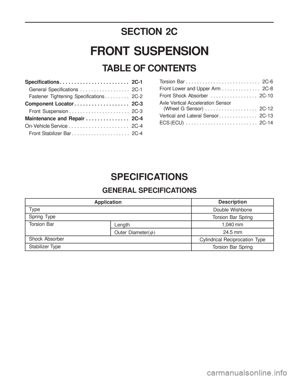
GENERAL SPECIFICATIONS
Type
Spring Type
Torsion Bar Shock Absorber
Stabilizer Type
Double Wishbone
Torsion Bar Spring 1,040 mm
24.5 mm
Cylindrical Reciprocation Type
Torsion Bar Spring
Specifications . . . . . . . . . . . . . . . . . . . . . . . . 2C-1General Specifications . . . . . . . . . . . . . . . . . . 2C-1
Fastener Tightening Specifications . . . . . . . . . 2C-2
Component Locator . . . . . . . . . . . . . . . . . . . 2C-3
Front Suspension . . . . . . . . . . . . . . . . . . . . . . 2C-3
Maintenance and Repair . . . . . . . . . . . . . . . 2C-4
On-Vehicle Service . . . . . . . . . . . . . . . . . . . . . 2C-4
Front Stabilizer Bar . . . . . . . . . . . . . . . . . . . . . 2C-4
Application Description
Torsion Bar . . . . . . . . . . . . . . . . . . . . . . . . . . . 2C-6
Front Lower and Upper Arm . . . . . . . . . . . . . . 2C-8
Front Shock Absorber . . . . . . . . . . . . . . . . .
2C-10
Axle Vertical Acceleration Sensor (Wheel G Sensor) . . . . . . . . . . . . . . . . . . . 2C-12
Vertical and Lateral Sensor . . . . . . . . . . . . . . 2C-13
ECS (ECU) . . . . . . . . . . . . . . . . . . . . . . . . . . 2C-14
Length Outer Diameter(
�)
Page 721 of 1574
2C-2 FRONT SUSPENSIONApplication
Torque Arm Bolt N
�m
40 - 60 60 - 80
FASTENER TIGHTENING SPECIFICATIONS
Stabilizer Bar
Application
Stabilizer Bar Retaining Nut Stabilizer Bar Link NutLower Arm Nut N
�m
30 - 45 60 - 80 16 - 22
Torsion Bar
Lower and Upper Arm
Application
Upper Arm Nut Upper Arm End Castle NutLower Arm Nut Lower Arm End Castle Nut N
�m
120 - 140 80 - 150
150 - 180 120 - 180
Steering Knuckle and Drive Shaft
Application
Brake Caliper Hose Bolt Brake Caliper Mounting Bolt
Tie Rod Retaining Nut Upper Arm Retaining NutLower Arm Retaining Nut N
�m
25 - 35
85 - 105 35 - 45
80 - 150
120 - 180
M10 M12
Page 722 of 1574
FRONT SUSPENSION 2C-3
COMPONENT LOCATOR
FRONT SUSPENSION
1 Shock Absorber
2 Upper Arm
3 Steering Knuckle
4 Lower Arm
5 Stabilizer Bar Link
6 Stabilizer Bar
7 Suspension Bumper
Page 723 of 1574
2C-4 FRONT SUSPENSIONMAINTENANCE AND REPAIR
ON-VEHICLE SERVICE
FRONT STABILIZER BAR
1 Front Stabilizer Bar
2 Bolt ...................................................... 30-45 Nm
3 Fixing Cap
4 Bushing
5 Nut ....................................................... 60-80 Nm
6 Stabilizer Bar Link Assembly
7 Outer Washer
8 Bushing
9 Center Washer
10 Lower Arm 11 Bushing
12 Outer Washer
13 Nut ....................................................... 16-22 Nm
Page 724 of 1574
FRONT SUSPENSION 2C-5
Removal & Installation Procedure
1. Remove the connecting nuts (1) from stabilizer bar link.Installation Notice
2. Remove the connecting nuts (2) of the stabilizer bar andlink and then remove the link. Installation Notice
3. Remove the stabilizer bar fixing cap bolts (arrow) and remove the stabilizer bar.
Tightening Torque 60 - 80 Nm
4. Installation should follow the removal precedure in the reverse order. Notice The distance between the end of the nut and the end of the link should be in 10-13 mm at the connection of the stabilizer bar link and lower arm.
Tightening Torque 30 - 45 Nm
Tightening Torque 16 - 22 Nm
Page 725 of 1574
2C-6 FRONT SUSPENSION TORSION BAR1 Nut
2 Torque Arm
3 Washer
4 Bolt ............................................ M10 : 40-60 Nm M12 : 60-80 Nm
5 Torsion Bar End Seat
6 Dust Cover
7 Torsion Bar
8 Dust Cover
9 Height Control Arm Assembly
10 Height Control Bolt End Piece
11 Height Control Bolt
12 Height Control Seat
Page 726 of 1574
FRONT SUSPENSION 2C-7
Removal & Installation Procedure
1. Remove the fixing nuts and bolts of the shock absorberand lower arm connection. Installation Notice
2. Remove the connecting nuts of the stabilizer bar link to the lower arm. Installation Notice
3. Turn the height control bolt until the distance between the end of the height control bolt end piece and the bolt end becomes 0-5 mm. Installation Notice Install the torsion bar spring and adjust the distance between the end of the height control bolt and piece end the bolt end to be 50-55 mm. Adjust the vehicle height.
Tightening Torque 60 - 80 Nm
Tightening Torque 16 - 22 Nm
4. Remove the torque arm fixing nuts and bolts and then withdraw the torsion bar spring. Installation Notice
M10 M12
Tightening Torque40 - 60 Nm 60 - 80 Nm
5. Installation should follow the removal precedure in thereverse order.
6. Check and adjust the wheel alignment.