Page 394 of 1574
OM600 ENGINE MECHANICAL 1B3-129
Tools Required 001 589 32 21 00 Dial Gauge Checking and Machining
1. Clean the valves and do visual check.Valves with wobbled valve disc, with worn or scored valve stem should be replaced.
2. Measure valve disc height ‘h’.
Service data
Intake
Exhaust 1.7 ± 0.15 mm 1.7 ± 0.15 mm
3. Machine the valve. Notice Pay attention to setting angle ‘� ’ .
Commercial Tool
Valve corn grinding machine
4. Measure radial runout between valve stem and valve seat.
Limit Max. 0.03mm
Dial Gauge 001 589 32 21 00
Page 442 of 1574
1B3-178 OM600 ENGINE MECHANICALHeight ‘A’
(cylinder head surface - cylinder head cover surface) Minimum height after machiningPermissible unevenness of parting surface Permissible variation of parallelism (longitud. Direction) Peak-to-valley height
Valve arrears ‘a’
Prechamber protrusion
Service Data
In longitudinal direction In transverse direction Intake valve Exhaust valve
142.9 - 143.1mm
142.5mm0.08mm0.0mm
Max. 0.1mm
0.0017mm
0.1 - 0.7mm 0.1 - 0.7mm 7.6 - 8.1mm
FACING CYLINDER HEAD MATING SURFACE
Preceding Work : Removal of prechamber Cylinder head pressure leakage test
1 Valve
2 Cylinder Head
3 Prechamber
A Height of Cylinder Head B Longitudinal Direction
C Transverse Direction
a Valve Arrears
b Prechamber Protrusion
Page 443 of 1574
OM600 ENGINE MECHANICAL 1B3-179
Measurement Procedure
1. Measure height ‘A’ .
Limit 142.5 mm
Notice If the height is less than 142.5mm, replace the cylinder head.
2. Insert the valve (1) and measure valve arrears ‘a’.
Valve Arrears ‘a’ 0.1 - 0.7 mm
Notice If out of standard, machine the valve seat.
3. Install the prechamber and measure protrusion ‘C’.
Protrusion ‘C’ 7.6 - 8.1mm
4. Assemble the engine and check the valve timing.
Page 446 of 1574
1B3-182 OM600 ENGINE MECHANICAL Service Data
Height ‘Y’
Permissible unevenness of contacting surface Permissible roughness upper contacting surface Permissible variation of parallelism of crankcase uppersurface to lower surface in longitudinal directionPiston protrusion at TDC to crankcase upper surface
In longitudinal direction (B) In transverse direction (C) Min. 299.62 mm
0.06 mm 0.06 mm
0.0006 - 0.0016 mm 0.05 mm
0.965 mm0.735 mm
Max. Min.
FACING CRANKCASE CONTACTING SURFACE
1 Crankcase
2 Crankcase Contacting Surface
Y Height (crankcase upper surface - crankcase lower surface) B Longitudinal Direction
C Transverse Direction H Chamfer Heightb Chamfer Angle
Page 452 of 1574

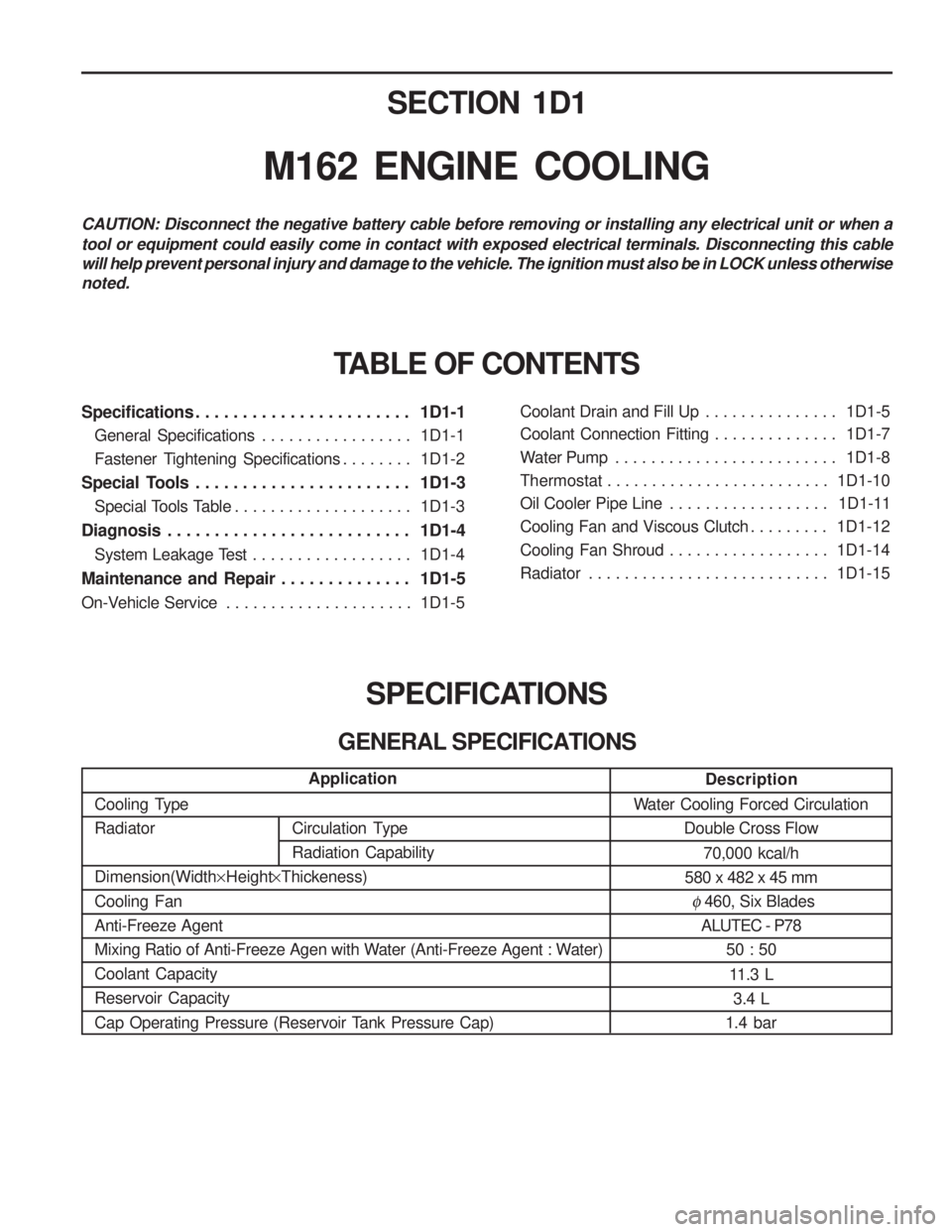
SECTION 1D1
M162 ENGINE COOLING
Specifications . . . . . . . . . . . . . . . . . . . . . . . 1D1-1General Specifications . . . . . . . . . . . . . . . . . 1D1-1
Fastener Tightening Specifications . . . . . . . . 1D1-2
Special Tools . . . . . . . . . . . . . . . . . . . . . . . 1D1-3 Special Tools Table . . . . . . . . . . . . . . . . . . . . 1D1-3
Diagnosis . . . . . . . . . . . . . . . . . . . . . . . . . . 1D1-4 System Leakage Test . . . . . . . . . . . . . . . . . . 1D1-4
Maintenance and Repair . . . . . . . . . . . . . . 1D1-5
On-Vehicle Service . . . . . . . . . . . . . . . . . . . . . 1D1-5Coolant Drain and Fill Up . . . . . . . . . . . . . . .
1D1-5
Coolant Connection Fitting . . . . . . . . . . . . . . 1D1-7
Water Pump . . . . . . . . . . . . . . . . . . . . . . . . . 1D1-8
Thermostat . . . . . . . . . . . . . . . . . . . . . . . . . 1D1-10
Oil Cooler Pipe Line . . . . . . . . . . . . . . . . . . 1D1-11
Cooling Fan and Viscous Clutch . . . . . . . . . 1D1-12
Cooling Fan Shroud . . . . . . . . . . . . . . . . . . 1D1-14
Radiator . . . . . . . . . . . . . . . . . . . . . . . . . . . 1D1-15
SPECIFICATIONS
GENERAL SPECIFICATIONS
CAUTION: Disconnect the negative battery cable before removing or installing any electrical unit or when a tool or equipment could easily come in contact with exposed electrical terminals. Disconnecting this cable will help prevent personal injury and damage to the vehicle. The ignition must also be in LOCK unless otherwisenoted.
TABLE OF CONTENTS
Description
Water Cooling Forced Circulation Double Cross Flow
70,000 kcal/h
580 x 482 x 45 mm
� 460, Six Blades
ALUTEC - P78
50 : 50
11.3 L 3.4 L
1.4 bar
Application
Cooling Type Radiator Dimension(Width ×Height ×Thickeness)
Cooling Fan Anti-Freeze Agent
Mixing Ratio of Anti-Freeze Agen with Water (Anti-Freeze Agent : Water)Coolant CapacityReservoir Capacity
Cap Operating Pressure (Reservoir Tank Pressure Cap)
Circulation Type Radiation Capability
Page 468 of 1574

Circulation Type RadiationCapabilitySECTION 1D2
M161 ENGINE COOLING
Specifications . . . . . . . . . . . . . . . . . . . . . . . 1D2-1
General Specifications . . . . . . . . . . . . . . . . . 1D2-1
Fastener Tightening Specifications . . . . . . . . 1D2-2
Special Tools . . . . . . . . . . . . . . . . . . . . . . . 1D2-3
Special Tools Table . . . . . . . . . . . . . . . . . . . . 1D2-3
Diagnosis . . . . . . . . . . . . . . . . . . . . . . . . . . 1D2-4 System Leakage Test . . . . . . . . . . . . . . . . . . 1D2-4
Maintenance and Repair . . . . . . . . . . . . . . 1D2-5
On-Vehicle Service . . . . . . . . . . . . . . . . . . . . . 1D2-5Coolant Drain and Fill Up . . . . . . . . . . . . . . .
1D2-5
Cooling Fan and Viscous Clutch . . . . . . . . . . 1D2-7
Coolant Pump . . . . . . . . . . . . . . . . . . . . . . . . 1D2-9
Thermostat . . . . . . . . . . . . . . . . . . . . . . . . . 1D2-11
Thermostat Housing Assembly . . . . . . . . . . 1D2-12
Removal and Installation of Cooling Fan Shroud . . . . . . . . . . . . . . . . . . . . . . . 1D2-14
Removal and Installation of Radiator . . . . . 1D2-15
SPECIFICATIONS
GENERAL SPECIFICATIONS
CAUTION: Disconnect the negative battery cable before removing or installing any electrical unit or when a tool or equipment could easily come in contact with exposed electrical terminals. Disconnecting this cable will help prevent personal injury and damage to the vehicle. The ignition must also be in LOCK unless otherwisenoted.
TABLE OF CONTENTS
Description
Water Cooling Forced Circulation Down Flow
61,500 kcal/h 58,000 kcal/h
680 x 415 x 25 mm680 x 415 x 28 mm
� 460, 9 Blades
ALUTEC-P78, Dragon Power Coolant A 50 : 5010.5 L 3.4 L
1.4 bar
Application
Cooling TypeRadiator Dimension(Width ×Height ×Thickeness)
Cooling Fan Anti-Freeze Agent
Mixing Ratio of Anti-Freeze Agen with Water (Anti-Freeze Agent : Water) Coolant Capacity Reservoir Capacity
Cap Operating Pressure (Reservoir Tank Pressure Cap)
Page 700 of 1574

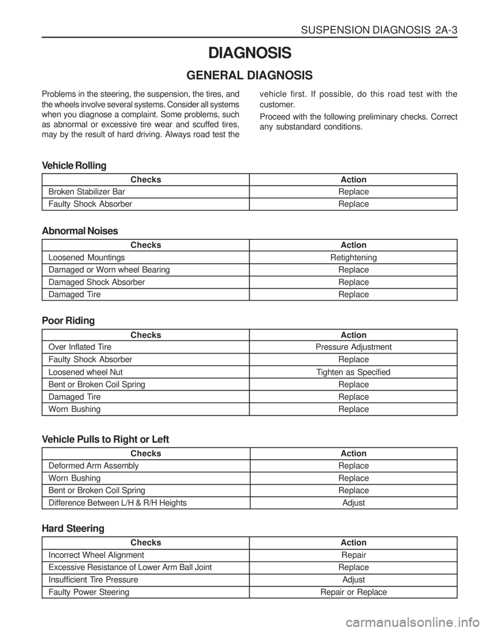
SUSPENSION DIAGNOSIS 2A-3
DIAGNOSIS
GENERAL DIAGNOSIS
Checks
Loosened Mountings Damaged or Worn wheel BearingDamaged Shock Absorber
Damaged Tire Action
Retightening ReplaceReplaceReplace
Abnormal Noises
Checks
Broken Stabilizer Bar Faulty Shock Absorber Action
ReplaceReplace
Vehicle Rolling
Checks
Over Inflated Tire Faulty Shock Absorber Loosened wheel Nut Bent or Broken Coil Spring
Damaged TireWorn Bushing Action
Pressure Adjustment
Replace
Tighten as Specified ReplaceReplaceReplace
Poor Riding
Problems in the steering, the suspension, the tires, and the wheels involve several systems. Consider all systems when you diagnose a complaint. Some problems, suchas abnormal or excessive tire wear and scuffed tires,may by the result of hard driving. Always road test the
vehicle first. If possible, do this road test with the
customer. Proceed with the following preliminary checks. Correct any substandard conditions.
Checks
Incorrect Wheel Alignment Excessive Resistance of Lower Arm Ball Joint
Insufficient Tire PressureFaulty Power Steering
Action Repair
Replace Adjust
Repair or Replace
Hard Steering
Checks
Deformed Arm Assembly Worn BushingBent or Broken Coil SpringDifference Between L/H & R/H Heights Action
ReplaceReplaceReplace Adjust
Vehicle Pulls to Right or Left
Page 715 of 1574

WHEEL ALIGNMENT 2B-5
VIBRATION DIAGNOSIS Wheel imbalance causes most highway speed vibration problems. A vibration can remain after dynamicbalancing because:
�A tire is out of round.
� A rim is out of round.
� A tire stiffness variation exists.
Measuring tire and wheel free runout will uncover only part of the problem, All three causes, known as loadedradial runout, must be checked using method of substituting known good tire and wheel assemblies on the problem vehicle. Preliminary Checks Prior to performing any work, always road test the car and perform a careful visual inspection for:
�
Obvious tire and wheel runout.
� Obvious drive axle runout.
� Improper tire inflation.
� Incorrect trim height.
� Bent or damaged wheels.
� Debris build-up on the tire or the wheel.
� Irregular or excessive tire wear.
� Improper tire bead seating on the rim,
� Imperfections in the tires, including: tread deformations, separations, or bulges from impactdamage. Slight sidewall indentations are normal and
will not affect ride quality.
Tire Balancing Balance is the easiest procedure to perform and should be done first if the vibration occurs at high speeds. Do an off-vehicle, two-plane dynamic balance first to correct
any imbalance in the tire and wheel assembly. An on-vehicle finish balance will correct any brake drum,
rotor, or wheel cover imbalance, If balancing does not correct the high-speed vibration, or if the vibration occurs at low speeds, runout is the probable cause.