2003 SSANGYONG MUSSO automatic transmission
[x] Cancel search: automatic transmissionPage 1211 of 1574
BODY WIRING SYSTEM 9A-9
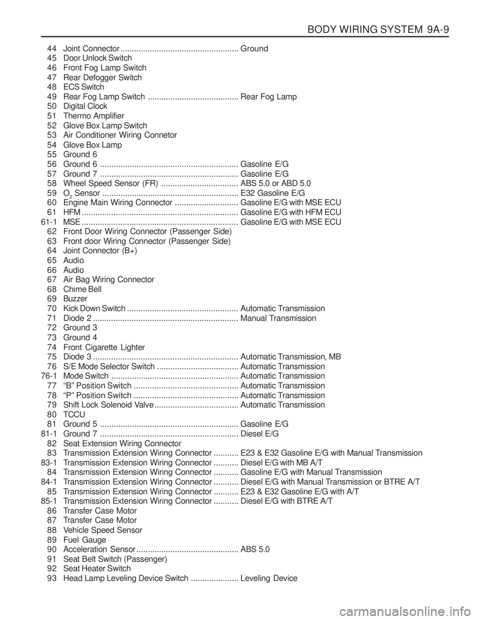
44 Joint Connector.................................................... Ground
45 Door Unlock Switch
46 Front Fog Lamp Switch
47 Rear Defogger Switch
4 8 ECS Switch
49 Rear Fog Lamp Switch ........................................Rear Fog Lamp
50 Digital Clock
51 Thermo Amplifier
52 Glove Box Lamp Switch
53 Air Conditioner Wiring Connetor
54 Glove Box Lamp
55 Ground 6
56 Ground 6 ............................................................. Gasoline E/G
57 Ground 7 ............................................................. Gasoline E/G
58 Wheel Speed Sensor (FR) ..................................ABS 5.0 or ABD 5.0
59 O 2 Sensor
............................................................ E32 Gasoline E/G
60 Engine Main Wiring Connector ............................Gasoline E/G with MSE ECU
61 HFM ..................................................................... Gasoline E/G with HFM ECU
61-1 MSE ..................................................................... Gasoline E/G with MSE ECU
62 Front Door Wiring Connector (Passenger Side)
63 Front door Wiring Connector (Passenger Side)
64 Joint Connector (B+)
65 Audio
66 Audio
67 Air Bag Wiring Connector
68 Chime Bell
6 9 Buzzer
70 Kick Down Switch ................................................. Automatic Transmission
71 Diode 2 ................................................................ Manual Transmission
72 Ground 3
73 Ground 4
74 Front Cigarette Lighter
75 Diode 3 ................................................................ Automatic Transmission, MB
76 S/E Mode Selector Switch ....................................Automatic Transmission
76-1 Mode Switch ........................................................ Automatic Transmission
77 “B” Position Switch .............................................. Automatic Transmission
78 “P” Position Switch .............................................. Automatic Transmission
79 Shift Lock Solenoid Valve .....................................Automatic Transmission
8 0 TCCU
81 Ground 5 ............................................................. Gasoline E/G
81-1 Ground 7 ............................................................. Diesel E/G
82 Seat Extension Wiring Connector
83 Transmission Extension Wiring Connector ...........E23 & E32 Gasoline E/G with Manual Transmission
83-1 T ransmission Extension Wiring Connector ...........Diesel E/G with MB A/T
84 Transmission Extension Wiring Connector ...........Gasoline E/G with Manual Transmission
84-1 T ransmission Extension Wiring Connector ...........Diesel E/G with Manual Transmission or BTRE A/T
85 Transmission Extension Wiring Connector ...........E23 & E32 Gasoline E/G with A/T
85-1 T ransmission Extension Wiring Connector ...........Diesel E/G with BTRE A/T
86 Transfer Case Motor
87 Transfer Case Motor
88 Vehicle Speed Sensor
89 Fuel Gauge
90 Acceleration Sensor ............................................. ABS 5.0
91 Seat Belt Switch (Passenger)
92 Seat Heater Switch
93 Head Lamp Leveling Device Switch .....................Leveling Device
Page 1212 of 1574
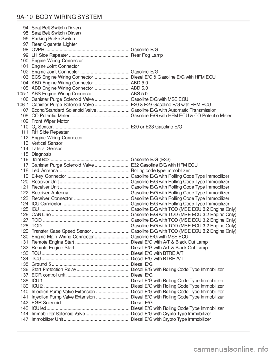
9A-10 BODY WIRING SYSTEM94 Seat Belt Switch (Driver)
95 Seat Belt Switch (Dirver)
96 Parking Brake Switch
97 Rear Cigarette Lighter
9 8 OVPR ................................................................. Gasoline E/G
99 LH Side Repeater ............................................... Rear Fog Lamp
100 Engine Wiring Connector
101 Engine Joint Connector
102 Engine Joint Connector ......................................Gasoline E/G
103 ECS Engine Wiring Connector ...........................Diesel E/G & Gasoline E/G with HFM ECU
104 ABD Engine Wiring Connector ...........................ABD 5.0
105 ABD Engine Wiring Connector ...........................ABD 5.0
105-1 ABS Engine Wiring Connector ............................ABS 5.0
106 Canister Purge Solenoid Valve ...........................Gasoline E/G with MSE ECU
106-1 Canister Purge Solenoid Valve ...........................E20 & E23 Gasoline E/G with FHM ECU
107 Econo/Standard Solenoid Valve .........................Gasoline E/G with Automatic Transmission
108 CO Potentio Meter .............................................. Gasoline E/G with HFM ECU & CO Potentio Meter
109 Front Wiper Motor 11 0 O 2 Sensor
........................................................... E20 or E23 Gasoline E/G
111 RH Side Repeater
112 Engine Wiring Connector
113 Vertical Sensor
114 Lateral Sensor
115 Diagnosis
11 6 Joint Box ............................................................. Gasoline E/G (E32)
117 Canister Purge Solenoid Valve ...........................E32 Gasoline E/G with HFM ECU
118 Led Antenna ...................................................... Rolling code type Immobilizer
119 E-key Connector ................................................ Gasoline E/G with Rolling Code Type Immobilizer
120 Receiver Unit ...................................................... Gasoline E/G with Rolling Code Type Immobilizer
121 Receiver Unit ...................................................... Gasoline E/G with Rolling Code Type Immobilizer
122 Receiver Antenna .............................................. Gasoline E/G with Rolling Code Type Immobilizer
123 Receiver Connector ........................................... Gasoline E/G with Rolling Code Type Immobilizer
124 ICU Connector .................................................... Gasoline E/G with Rolling Code Type Immobilizer
125 ICU ..................................................................... Gasoline E/G with TOD (MSE ECU 3.2 Engine Only)
126 CAN Line ............................................................ Gasoline E/G with TOD (MSE ECU 3.2 Engine Only)
127 TOD ................................................................... Gasoline E/G with TOD (MSE ECU 3.2 Engine Only)
128 TOD ................................................................... Gasoline E/G with TOD (MSE ECU 3.2 Engine Only)
129 Transfer Case Speed Sensor .............................Gasoline E/G with TOD (MSE ECU 3.2 Engine Only)
130 Engine Main Wiring Connector ...........................Gasoline E/G with MSE ECU
131 Remote Engine Start .......................................... Diesel E/G with A/T & Black Out Lamp
132 Remote Engine Start .......................................... Diesel E/G with A/T & Black Out Lamp
133 TCU .................................................................... Diesel E/G with BTRE A/T
134 TCU .................................................................... Diesel E/G with BTRE A/T
135 Ground 5 ............................................................ Diesel E/G
136 Start Protection Relay .........................................Diesel E/G with Rolling Code Type Immobilizer
137 EGR control unit ................................................. Diesel E/G
1 3 8 ICU 1 .................................................................. Diesel E/G with Rolling Code Type Immobilizer
1 3 9 ICU 2 .................................................................. Diesel E/G with Rolling Code Type Immobilizer
140 Injection Pump Valve Extension ..........................Diesel E/G with Rolling Code Type Immobilizer
141 Injection Pump Valve Extension ..........................Diesel E/G with Rolling Code Type Immobilizer
142 EGR Solenoid .................................................... Diesel E/G
143 ICU led ................................................................ Diesel E/G with Rolling Code Type Immobilizer
144 Immobilizer Solenoid Valve ..................................Diesel E/G with Crypto Type Immobilizer
147 Immobilizer Unit ................................................... Diesel E/G with Crypto Type Immobilizer
Page 1226 of 1574
9A-24 BODY WIRING SYSTEM
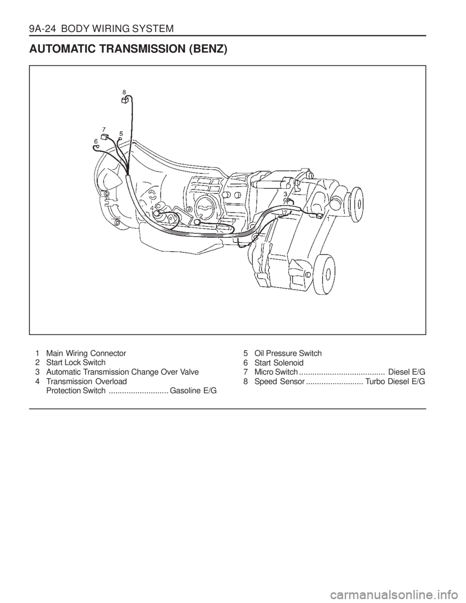
AUTOMATIC TRANSMISSION (BENZ)1 Main Wiring Connector
2 Start Lock Switch
3 Automatic Transmission Change Over Valve
4 Transmission Overload Protection Switch ...........................Gasoline E/G 5 Oil Pressure Switch
6 Start Solenoid
7 Micro Switch
....................................... Diesel E/G
8 Speed Sensor .......................... T urbo Diesel E/G
Page 1227 of 1574
BODY WIRING SYSTEM 9A-25
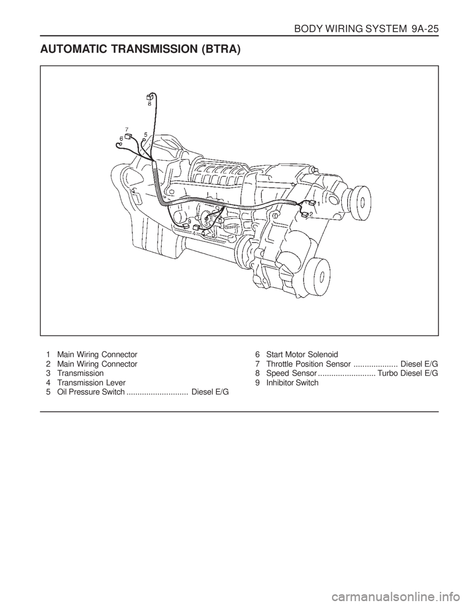
AUTOMATIC TRANSMISSION (BTRA)1 Main Wiring Connector
2 Main Wiring Connector
3 Transmission
4 Transmission Lever
5 Oil Pressure Switch ............................Diesel E/G6 Start Motor Solenoid
7 Throttle Position Sensor
....................Diesel E/G
8 Speed Sensor .......................... T urbo Diesel E/G
9 Inhibitor Switch
Page 1315 of 1574
MUSSO-SPORTS 1A-3
SUPPLEMENT
HUBER EGR
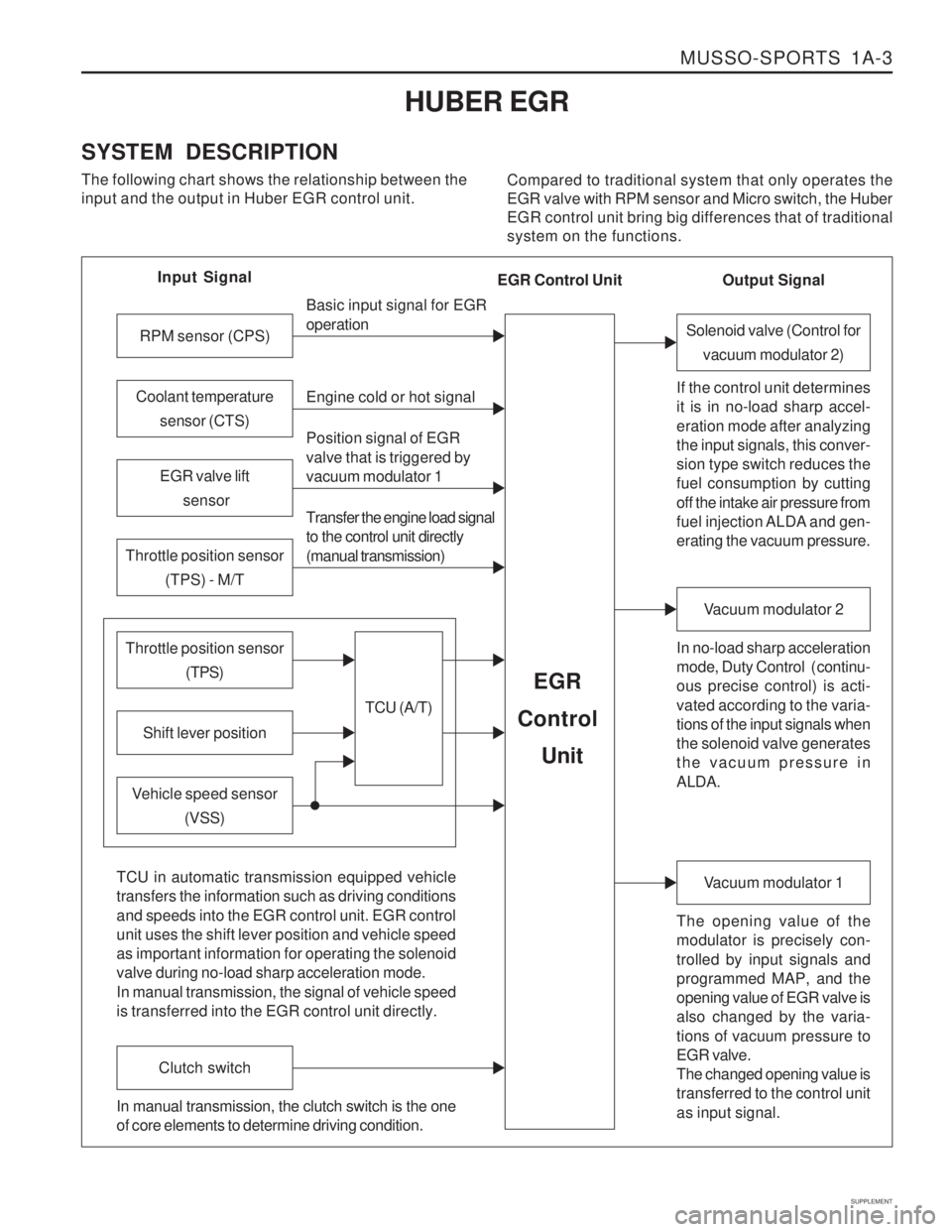
SYSTEM DESCRIPTION The following chart shows the relationship between the input and the output in Huber EGR control unit. Compared to traditional system that only operates theEGR valve with RPM sensor and Micro switch, the HuberEGR control unit bring big differences that of traditionalsystem on the functions.
Input Signal
RPM sensor (CPS)
EGR valve lift sensor
Throttle position sensor (TPS) - M/T
Shift lever position
Throttle position sensor (TPS)
Vehicle speed sensor(VSS) Basic input signal for EGR operation Engine cold or hot signal
Position signal of EGR valve that is triggered by vacuum modulator 1 Transfer the engine load signal to the control unit directly (manual transmission)
TCU (A/T)
EGR
Control
Unit
Coolant temperature sensor (CTS)
Solenoid valve (Control forvacuum modulator 2)
If the control unit determines it is in no-load sharp accel- eration mode after analyzing the input signals, this conver- sion type switch reduces the fuel consumption by cutting off the intake air pressure from
fuel injection ALDA and gen- erating the vacuum pressure. In no-load sharp acceleration
mode, Duty Control ( continu- ous precise control) is acti- vated according to the varia- tions of the input signals when the solenoid valve generates the vacuum pressure in ALDA.
Vacuum modulator 2
The opening value of the modulator is precisely con- trolled by input signals and programmed MAP, and the opening value of EGR valve is also changed by the varia- tions of vacuum pressure to EGR valve. The changed opening value is transferred to the control unit as input signal.
Vacuum modulator 1
TCU in automatic transmission equipped vehicle transfers the information such as driving conditions and speeds into the EGR control unit. EGR control unit uses the shift lever position and vehicle speed as important information for operating the solenoid valve during no-load sharp acceleration mode. In manual transmission, the signal of vehicle speed is transferred into the EGR control unit directly.
Clutch switch
In manual transmission, the clutch switch is the one of core elements to determine driving condition. Output Signal
EGR Control Unit
Page 1316 of 1574
1A-4 MUSSO-SPORTS
SUPPLEMENT
from vacuum pump
EGR valve
EGR control unit
KAA5A020
KAA5A020
KAA5A020
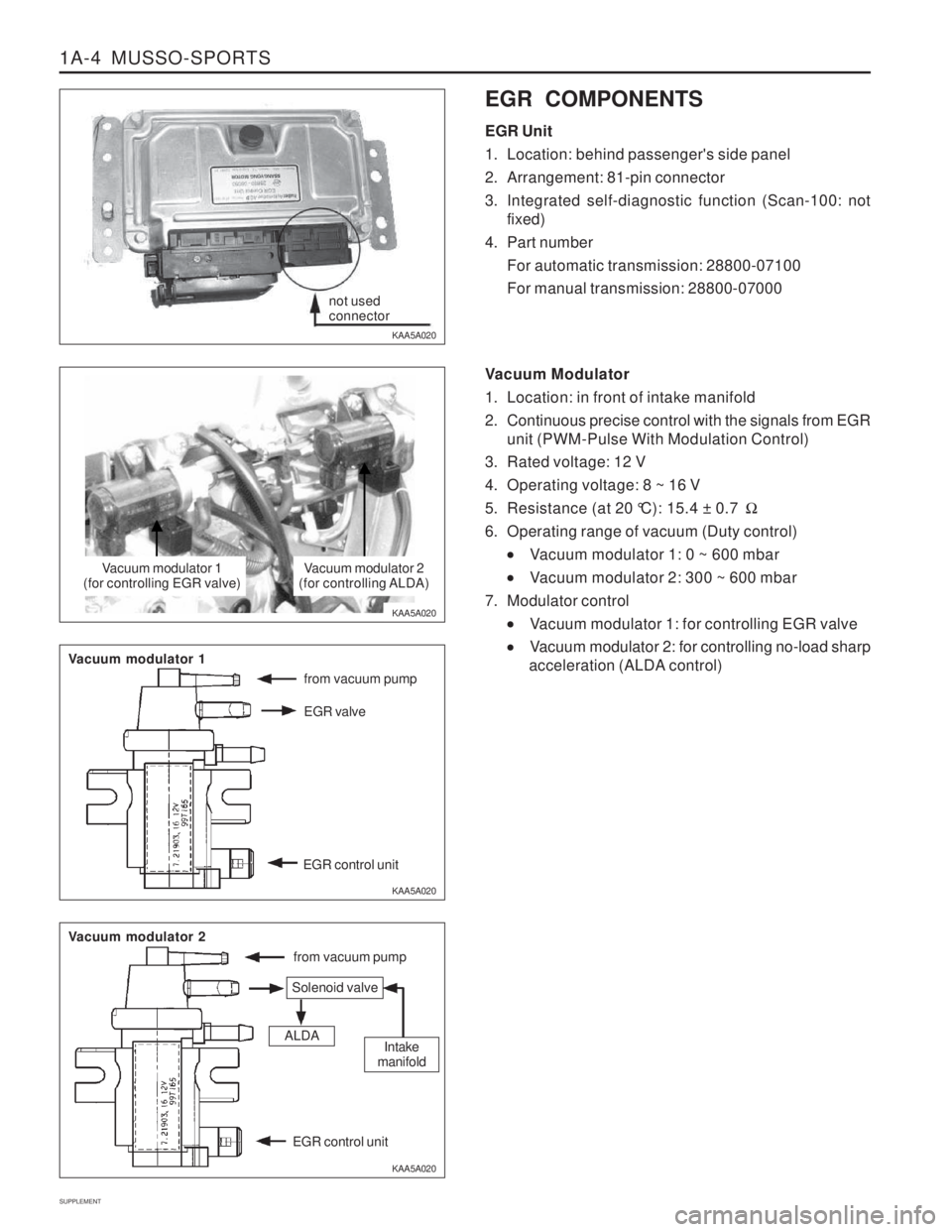
KAA5A020 EGR COMPONENTS EGR Unit
1. Location: behind passenger's side panel
2. Arrangement: 81-pin connector
3. Integrated self-diagnostic function (Scan-100: not
fixed)
4. Part number For automatic transmission: 28800-07100 For manual transmission: 28800-07000
Vacuum Modulator
1. Location: in front of intake manifold
2. Continuous precise control with the signals from EGR unit (PWM-Pulse With Modulation Control)
3. Rated voltage: 12 V
4. Operating voltage: 8 ~ 16 V
5. Resistance (at 20 °C): 15.4 ± 0.7 �
6. Operating range of vacuum (Duty control)
Vacuum modulator 1: 0 ~ 600 mbar
Vacuum modulator 2: 300 ~ 600 mbar
7. Modulator control
Vacuum modulator 1: for controlling EGR valve
Vacuum modulator 2: for controlling no-load sharp
acceleration (ALDA control)
not used connector
Vacuum modulator 1
(for controlling EGR valve)Vacuum modulator 2
(for controlling ALDA)
from vacuum pump
Vacuum modulator 1
Vacuum modulator 2
Solenoid valve
ALDAIntake
manifold
EGR control unit