Page 1098 of 1574

TRANSFER CASE (TOD) 5D2-9
4H/4L Switch Input4H 4H 4H 4H 4H 4H4H4H4H
4L 4L 4L4L 4L 4L4L4L 4L
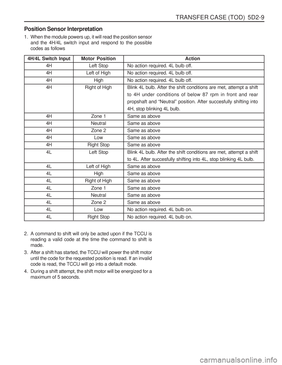
Position Sensor Interpretation
1. When the module powers up, it will read the position sensor
and the 4H/4L switch input and respond to the possible codes as follows
2. A command to shift will only be acted upon if the TCCU is reading a valid code at the time the command to shift ismade.
3. After a shift has started, the TCCU will power the shift motor until the code for the requested position is read. If an invalidcode is read, the TCCU will go into a default mode.
4. During a shift attempt, the shift motor will be energized for a maximum of 5 seconds. Motor Position
Left Stop
Left of High
High
Right of High
Zone 1
Neutral
Zone 2 Low
Right Stop
Left Stop
Left of High High
Right of High
Zone 1
Neutral Zone 2 Low
Right Stop Action
No action required. 4L bulb off. No action required. 4L bulb off. No action required. 4L bulb off. Blink 4L bulb. After the shift conditions are met, attempt a shiftto 4H under conditions of below 87 rpm in front and rearpropshaft and “Neutral ” position. After succesfully shifting into
4H, stop blinking 4L bulb. Same as above Same as aboveSame as aboveSame as aboveSame as above Blink 4L bulb. After the shift conditions are met, attempt a shift to 4L. After succesfully shifting into 4L, stop blinking 4L bulb.Same as aboveSame as aboveSame as above Same as above Same as aboveSame as aboveNo action required. 4L bulb on. No action required. 4L bulb on.
Page 1148 of 1574

6A-6 POWER STEERING SYSTEM
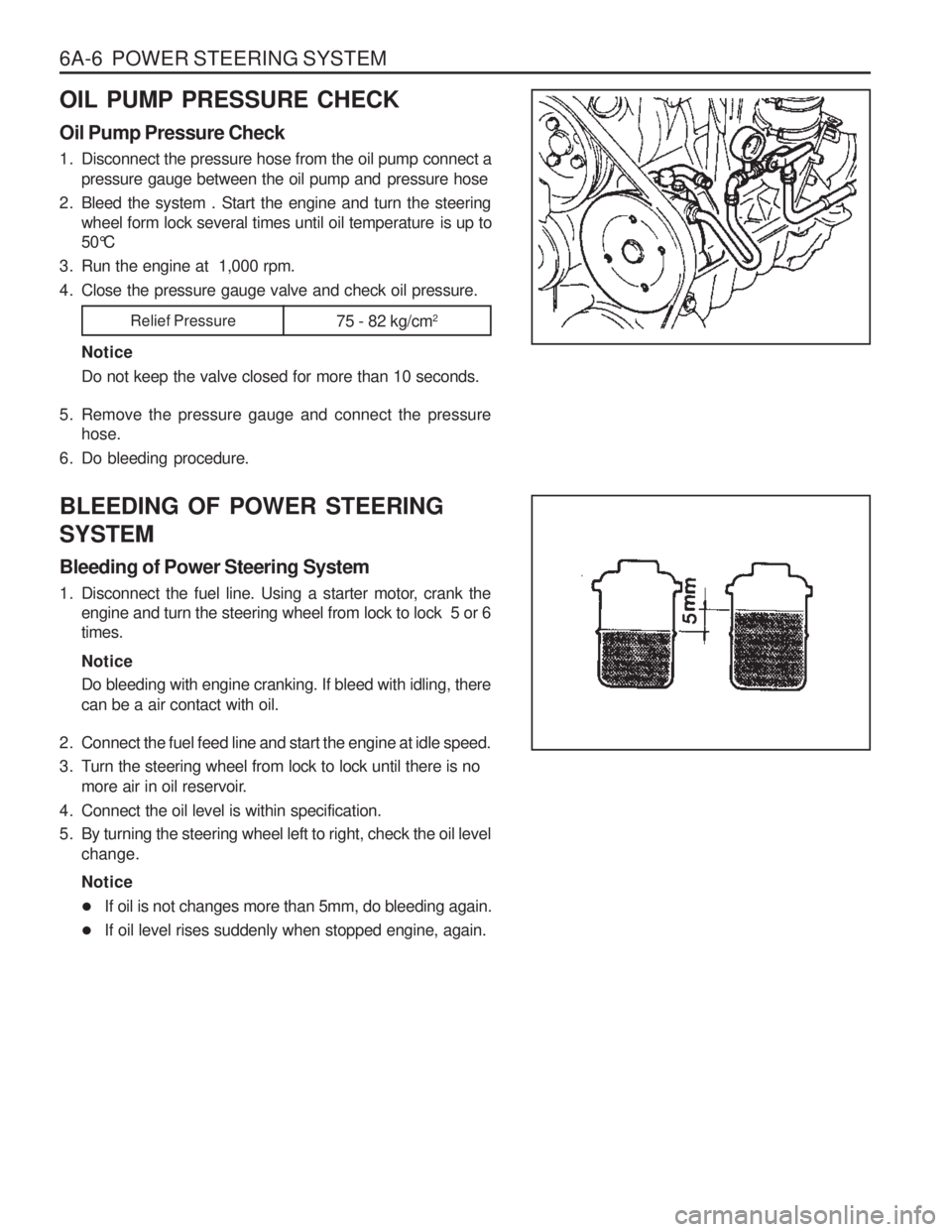
OIL PUMP PRESSURE CHECK Oil Pump Pressure Check
1. Disconnect the pressure hose from the oil pump connect apressure gauge between the oil pump and pressure hose
2. Bleed the system . Start the engine and turn the steering wheel form lock several times until oil temperature is up to
50°C
3. Run the engine at 1,000 rpm.
4. Close the pressure gauge valve and check oil pressure.
NoticeDo not keep the valve closed for more than 10 seconds.
5. Remove the pressure gauge and connect the pressure hose.
6. Do bleeding procedure. BLEEDING OF POWER STEERING SYSTEM Bleeding of Power Steering System
1. Disconnect the fuel line. Using a starter motor, crank the engine and turn the steering wheel from lock to lock 5 or 6 times. Notice Do bleeding with engine cranking. If bleed with idling, there can be a air contact with oil.
2. Connect the fuel feed line and start the engine at idle speed.
3. Turn the steering wheel from lock to lock until there is no more air in oil reservoir.
4. Connect the oil level is within specification.
5. By turning the steering wheel left to right, check the oil level change. Notice
� If oil is not changes more than 5mm, do bleeding again.
� If oil level rises suddenly when stopped engine, again.
Relief Pressure
75 - 82 kg/cm2
Page 1200 of 1574
8B-20 SUPPLEMENTAL RESTRAINT SYSTEM(SRS) Removal & Installation Procedure preceding work : removal of steering wheel
1. Turn the ignition switch to “OFF” position and disconnectthe battery negative cable. Start the procedure after waiting over 3oseconds.
2. Unscrew 3 screws from lower cover on steering column shaft and remove the lower cover.
3. Unscrew 4 screws from clock spring and remove the clock
spring
Installation Notice
� Don’t try to repair and modify the clock spring.
� When aligning the neutral position, turn to clockwise until it stops, and turn to counter clockwise until the marks are aligned
Page 1367 of 1574

USAGE AND CAPACITY OF FUSES IN FUSE BOX 4-3
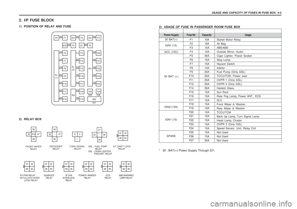
2. I/P FUSE BLOCK
1) POSITION OF RELAY AND FUSE 2) USAGE OF FUSE IN PASSENGER ROOM FUSE BOX
* 30 : BAT(+) Power Supply Through Ef1.
15A10A
10A15A10A
20A10A10A
10AST F110AIG1 F210AIG1 F3
ACC10AF4 B+30AF5
B+
(1) F6
F13
IG1
F20
15AF730AF1410AF21
F8F15F22
20AF915AF1610AF23
F10
B+
(2)
F17
F24
20AF1115AF1810A 15A
20AF1210AIG2 F19
30A
F25 F26
F27
85
87a3087
86
85
-3087
86
BE
L
85-
30
87
86
2) RELAY BOX
FRONT WIPERRELAY DEFOGGER
RELAY TURN SIGNAL
RELAY GSL : FUEL PUMP RELAYDSL : CIGAR LIGHTER, P/SOCKET RELAY A/T SHIFT LOCK
RELAY
8730
8685
8730
8685
8730
8685
8730
8685
A/T:PNP RELAY M/T:CLUTCH INTER LOCK RELAY SUNROOF
RELAY 'B' S/W
INTERLOCK RELAY POWER WINDER
RELAY 10A 10A10A10A30A15A15A10A20A20A20A20A30A15A15A10A 15A 10A10A10A10A10A10A10A15A30A
F1F2F3F4F5F6F7F8F9
F10 F11F12F14F15F16F17 F18 F19F20F21F22F23F24F25F26F27
Fuse No Capacity Usage
Starter Motor Relay Air BagABS/ABDOutside Mirror, AudioCigar Lighter, Power SocketStop LampHazard SwitchInteriorFuel Pump (Only GSL)TCCU/TOD, Power seatOVPR 1 (Only GSL)OVPR 4 (Only GSL)Heated GlassSun RoofRear Fog Lamp, Power ANT., ECSDLCFront Wiper & WasherRear Wiper & WasherTCCU/TCMBack Up Lamp, Turn Signal LampHead Lamp, Cluster OVPR 3 (Only GSL) Speed Sensor, Unit, Relay CoilNot UsedNot UsedNot Used
Power Supply
30 BAT(+)
ACC (15C) IGN2 (15A)
30 BAT (+)
IGN1 (15)
IGN1 (15)
SPARE
8730
8685
8730
8685
ECS
RELAY ABS WARNING
LAMP RELAY
8730
8685
Page 1429 of 1574
ELECTRICAL WIRING DIAGRAMS 5-63
W/H MAIN (I/P)
c. POSITION OF CONNECTORS AND GROUNDS
W/H MAIN (GSL)
C109
C111 C112
C101, C102 S101, C104C103d. SPLICE PACK S201 (BLACK)
1 2 3 4
5 6 7 8
5C204
LW
LW
DLC '2' Stics '29'
EGR Control unit '3' (DLC) Clock '3'VSS '3' F24 (10A)
Seat Warmer Control unit '9'
Stop Lamp Switch '3' (GSL)
LW LW LW LW LW
TP Sensor Connector
(BTRE A/T)
Micro Switch (EGR)
Starter Motor "ST"
C210, C209 C206, C206BC207C208, C208B
'P' Position Sensor
PNP Switch
Oil Pressure Swich
Speed Sensor
W/H T/M