Page 132 of 1574
1B1-96 M162 ENGINE MECHANICAL3 Oil Filler Cap 4 Dipstick Gauge
9. Fill up engine oil through the engine oil filler opening (3).
10. Check for oil leaks at normal engine temperature after starting the engine.
11. Stop the engine and wait 5 minutes. Check the oil level and fill up as specified if necessary.
Page 252 of 1574

1B2-100 M161 ENGINE MECHANICAL9. Fill up engine oil through the engine oil filler opening.
10. Check for oil leaks at normal engine temperature after starting the engine.
11. Stop the engine and wait 5 minutes. Check the oil level and fill up as specified if necessary.
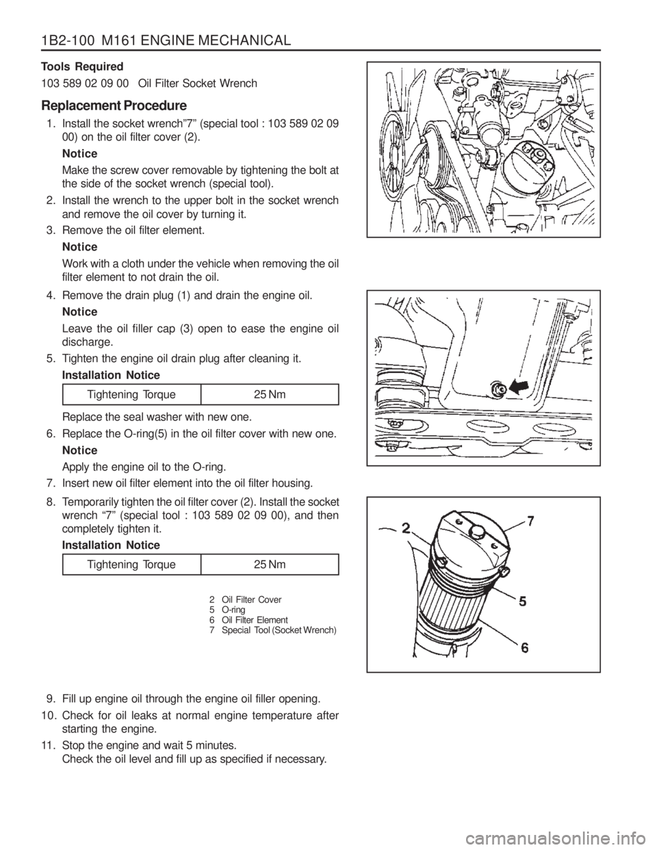
4. Remove the drain plug (1) and drain the engine oil.
Notice Leave the oil filler cap (3) open to ease the engine oil discharge.
5. Tighten the engine oil drain plug after cleaning it. Installation Notice
Tools Required
103 589 02 09 00 Oil Filter Socket Wrench Replacement Procedure
1. Install the socket wrench ”7” (special tool : 103 589 02 09
00) on the oil filter cover (2). NoticeMake the screw cover removable by tightening the bolt at the side of the socket wrench (special tool).
2. Install the wrench to the upper bolt in the socket wrench and remove the oil cover by turning it.
3. Remove the oil filter element.
Notice Work with a cloth under the vehicle when removing the oil filter element to not drain the oil. Replace the seal washer with new one.
6. Replace the O-ring(5) in the oil filter cover with new one.
Notice Apply the engine oil to the O-ring.
7. Insert new oil filter element into the oil filter housing.
Tightening Torque 25 Nm
8. Temporarily tighten the oil filter cover (2). Install the socket wrench “7” (special tool : 103 589 02 09 00), and then
completely tighten it. Installation Notice
2 Oil Filter Cover
5 O-ring
6 Oil Filter Element
7 Special Tool (Socket Wrench)
Tightening Torque 25 Nm
Page 367 of 1574

1B3-102 OM600 ENGINE MECHANICAL
CheckingNotice The noise which continues short time during short travel (frequent starting of the engine) or engine starting after a long time storage is normal operating conditions. So, it doesnot need to be repaired. Determine the malfunctions in valveclearance compensation device with noise through following
tests. If defective, replace as respectively.
1. Run the engine at more than 3000rpm for approx. 4 minutes.
2. Stop the engine. After 5minutes, check the engine oil level and adjust if necessary.
3. Remove the cylinder head cover.
4. Check the valve tappets at TDC position of each cylinders.
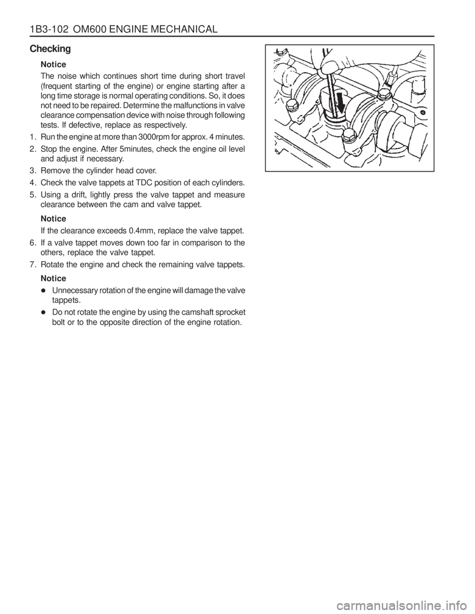
5. Using a drift, lightly press the valve tappet and measure clearance between the cam and valve tappet. Notice If the clearance exceeds 0.4mm, replace the valve tappet.
6. If a valve tappet moves down too far in comparison to the others, replace the valve tappet.
7. Rotate the engine and check the remaining valve tappets.
Notice
� Unnecessary rotation of the engine will damage the valve tappets.
� Do not rotate the engine by using the camshaft sprocket bolt or to the opposite direction of the engine rotation.
Page 628 of 1574
1F3-18 OM600 ENGINE CONTROLS
Min. volume 150cm for 30 seconds
FUEL PUMP TEST Notice
Before test, replace the fuel filter cartridge and fuel prefilter.
Fuel Feed Test
1. Disconnect the fuel return line (1) and seal up it with plug.
2. Insert the plastic hose (5) and put the end into the measuring
beaker (6).
3. Disconnect the vacuum line (4) from vacuum unit (engine stop) (5) and connect the vacuum pump (7) to the vacuum unit.
4. To avoid the engine starting, build up vacuum (approx. 500 mbar).
5. Operate the starter motor for exactly 30 seconds and measure fuel volume in the beaker.
3
Page 630 of 1574
1F3-20 OM600 ENGINE CONTROLS
Tools Required
617 589 04 21 00 Tester
1. Disconnect the fuel line (2) from the fuel filter.
2. Remove the banjo bolt (4) from the fuel injection pump andremove the seals (3) and fuel line (2).
3. Connect the tester (5).
4. Start the engine and read off the fuel pressure on tester (5). Notice If out of standard, replace the fuel feed pump.
Tester 617 589 04 21 00
5. Stop the engine. At Idle Speed
At Full load
> 0.3bar > 0.5bar
6. Remove the tester.
7. Replace the seal and connect the fuel line (2).
Page 651 of 1574
OM600 ENGINE CONTROLS 1F3-41
With Pulse Generator
Tools Required 617 589 09 21 00 Rl Sensor
617 589 10 21 00 Timing Tester667 589 00 21 00 TDC Pulse Generator
Commercial Tools
Item
Digital Tester
Without Pulse Generator Tools
Bosch, MOT 001.03
Hartmann & Braun, EOMT3 Bosch, ETD 019.00Sun, DIT 9000
ALV, Diesel - Tester 875
Test Procedure
1. Remove the screw plug (7) and seal (8) collect oil in a suitable vessel.
2. Install the Rl sensor into the governor housing of injection pump (1).
Rl Sensor 617 589 10 21 00
3. Connect the digital tester and TDC pulse sender unit according to connection diagram.
4. Run the engine at idle speed and check the Rl value on the digital tester Notice
If out of standard, adjust the start of delivery.
5. Stop the engine.
6. Remove the Rl sensor, digital tester and TDC pulse sender unit.
7. Replace the seal and tighten the plug.
8. Check engine oil level and adjust if necessary.
Rl value A TDC 14° - 16 °
Tightening Torque 30 Nm
Page 820 of 1574
POWER BOOSTER 4C-5
PEDAL STROKE INSPECTION
1. Start the engine and stop it after one or two minutes.Depress the brake pedal several times. If the pedal goes down furthest the first time, but gradually rises after the second or third time, brake booster is normal.If there is no change in pedal stroke, the brake booster is abnormal.
2. Depress the brake pedal several times with engine stopped, and depress the brake pedal and start the engine. If the
pedal goes down slightly, the booster is normal.
3. Depress the brake pedal with engine running, and stop it with the pedal depressed. If there is no change in pedalheight during 30 sec., the booster is normal.
Page 939 of 1574

5A-80 AUTOMATIC TRANSMISSION6. Switch off the engine and raise the vehicle on the hoist, if applicable, ensuring that the vehicle is level.
7. Three minutes after the engine has stopped, but no longer than one hour, remove the filler pump, The correct level is reached when ATF is aligned with the bottom of the filler hole. If the correct level is not reached, then add
a small quantity of ATF to the correct level.
8. Replace the transmission filler plug and clean all remnants of ATF on the transmission and vehicle.
9. Tighten the transmission filler plug to specification.
Checking, Adding Fluid and Filling - Drained or Dry Transmission
To set the correct fluid level proceed as follows. 1. Set the transmission selector to Park and switch the engine off.
2. Raise the vehicle on a hoist (or leave over a service pit).
3. Clean all dirt from around the service fill plug prior to removing the plug, Remove the oil service fill plug. Clean the fill plug and check that there is no damage to the ‘O’ ring. Install the filler pump into the filler hole.
4. Lower the vehicle with the filler pump still connected and partially fill the transmission. This typically requires approximately :
a. If the transmission torque converter is empty:
9.0 litres - 4WD9.0 litres - RWD
b. If the transmission torque converter is full: 4.5 litres - 4WD4.5 litres - RWD
5. Start the vehicle in Park with the Parking brake and foot brake applied with the engine idling, cycle the transmission gear selector through all positions, adding ATF until gear application is felt.
6. Then add an additional 0.5 litres of ATF.
7. Switch off the engine and raise the vehicle on the hoist. Remove the filler pump and replace the filler plug. The plug shall be tightened to specification.
8. The vehicle is then to be driven between 3.5 and 4.5 kilometers at light throttle so that the engine does not exceed 2500 rpm. This should result in the transmission temperature being in the range 50 to 60 °C.
9. With the engine idling, cycle the transmission selector through all gear positions with the brake applied.
10. Stop the engine. Raise the vehicle on the hoist, if applicable ensuring the vehicle is level.
11. Three minutes after the engine has stopped, but no longer than one hour, remove the filler plug. The correct level is reached when ATF is aligned with the bottom of the filler hole. If the correct level is not reached, then add
a small quantity of ATP to the correct level.
12. Replace the transmission filler plug and clean all remnants of ATF on the transmission and vehicle. Tighten the transmission Filler plug to specification.
ELECTRONIC ADJUSTMENTS Idle Speed Adjustment
Carry out the adjustments to the idle speed as detailed in the workshop manual.
Throttle Position Calibration
Should the throttle position data stored in the TCU be lost or be out of specification, as indicated by a diagnostic
trouble message, it may be re-established by the following procedure. � Check that the hot engine idle speed is within specification.
� Allow the engine to idle in ‘Drive ’ for 60 seconds with the air conditioner (if fitted) turned off. The closed throttle
reference point in the TCU has now been set.
Switch the engine off but leave the ignition on. Hold the accelerator pedal on the floor for 60 seconds. The wide open
throttle reference point in the TCU has now been set.