2003 SSANGYONG MUSSO fuse
[x] Cancel search: fusePage 846 of 1574

ANTILOCK BRAKE SYSTEM 4F-17
Application
Power Voltage
Residual Temperature Measurement (ABD only) Acceleration Sensor Signal (wire)Defect Code
28 29 42Description
when switch knob (planger) is pressed by 3mm : �
- Each ends resistance value of the switch when switch knob(plunger) is not pressed : less than 200 m �
� When brake is applied :
ECU (ABS:No.14, ABD:No.48) terminal 11 - 14 V
or VBattery.When brake is released : ECU (ABS:No.14, ABD:No.48) terminal 0 V
� Check battery voltage.
� Resistance between ECU (ABD:No.28 & 29,
ABS:No.19) pins and battery negative terminal :
less than 20 m �
� Resistance between ECU No.1 (ABS:NO.15) pin and
ignition terminal : less than 60 m �
� Check that normal voltage is applied to ECU
(ABD:No.1, ABS:No.15) pin when ignition switch is turned to "ON" or "OFF".
� Check ABS fuses of 15A and 80A.
� Replace the ECU.
� Check wire (ECU No.50) for open or loose contact.
� Check connection between connectors.
� Check relevant wires for open or short.(When connector is removed)
� Check voltage between ECU side ground (ABD:No.1,
ABS:No.15 pin) and acceleration sensor side ground(ABD:No.1, ABS:No.15 pin / ECU side ABD:No.39, ABS:No.30 pin)
(When connector is installed and power is applied)
- Voltage : less than 0.25 V
� Check voltage among related terminals.(When connector is installed and power is applied)
- Voltage between ECU (ABD:No.43, ABS:No.28 pin
and ABD:No.39, ABS:No.30 pin) : 4.75 - 5.25 V
- Signal voltage between ECU (ABD:No.51, ABS:No.10) pin and (ABD:No.39, ABS:No.30) pin : 1.95 V - 3.45 V
(Measure it by laying acceleration sensor horizon- tally and without external force)
Page 1096 of 1574

TRANSFER CASE (TOD) 5D2-7
1. K-LINE : Communication line for coding and diagnosis with SCANNER.
Classification of Pin No.
Classification
Pin No. Pin Name Description
Power Supply 17,18
Ground
TOD control unit ground
4,19 Battery TOD control unit battery supply : (Fuse No 13,20A)
5 Ignition Ignition ON / OFF
27 Position 1
Position encoder 1 : check of shift motor position
10 Position 2 Position encoder 2 : check of shift motor position
28 Position 3
Position encoder 3 : check of shift motor position
30 Position 4
Position encoder 4 : check of shift motor position
9 4H/4L Switch Transfer case mode input
24 Auto T/M Neutral Check of neutral gear position in Auto T/M 16 Speed 5V supply (TPS / speed sensor)
11 Front Speed
Front speed sensor signal input
Signal Input
29 Rear Speed Rear speed sensor signal input
25 ABS Operation
ABS ON / OFF
6 Position Return
Position encoder ground
13 Speed / TPS Return Ground for speed sensor / TPS
2 2 CAN-L CAN bus low line
23 CAN-H
CAN bus high line
2,15 Motor LO-HI Motor output port
- LO to HI : join with battery
- HI to LO (or motor brake) : join with ground
1,14 Motor HI-LO Motor output port
- HI to LO : join with battery
- LO to HI (or motor brake) : join with ground
3 EMC TOD output
Signal Output
21 4L Illumination Illuminates
“4L ” indicator
7 Diagnosis Display
4WD check lamp illuminator
- Upon defect ; Ground circuit
20K-LINE1)
Diagnosis
Page 1107 of 1574
5D2-18 TRANSFER CASE (TOD) CODING
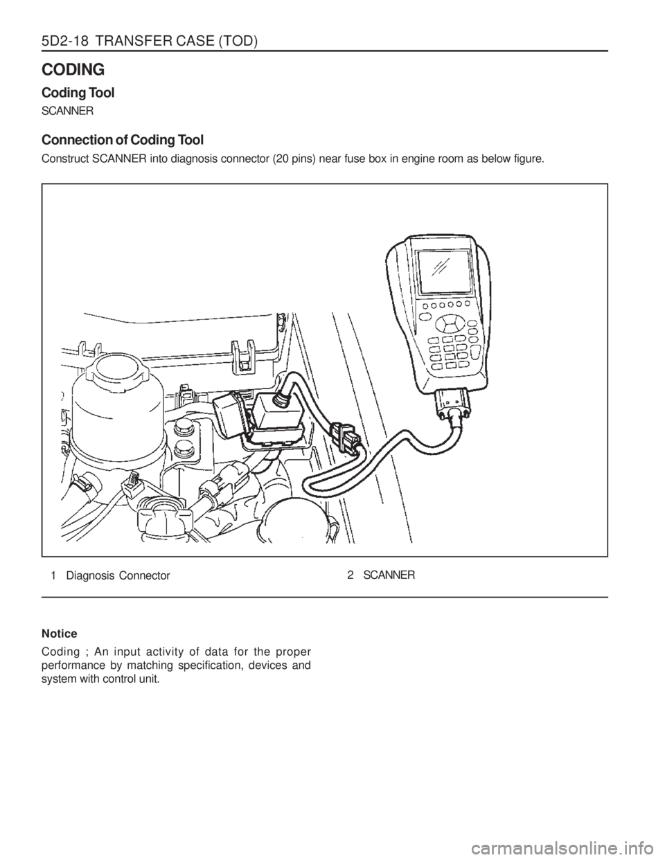
Coding Tool SCANNER
Connection of Coding Tool Construct SCANNER into diagnosis connector (20 pins) near fuse box in engine room as below figure.
1 Diagnosis Connector2 SCANNER
Notice Coding ; An input activity of data for the proper performance by matching specification, devices andsystem with control unit.
Page 1110 of 1574

TRANSFER CASE (TOD) 5D2-21
DIAGNOSIS Malfunction interior TOD control unit ; fault code 1714
�Phenomenon
1. When ignition “ON ”, “4WD CHECK ” lamp illuminates
continuously.
2. On diagnosis by SCAN-100, it displays fault code “1714 ”.
� Cause ; Error of EEPROM checksum in TOD control unit
Test Stage / Contents
Result
Stage T est Contents and Procedure Specified Value
/Yes/No Countermeasure
Check power supply for TOD control unit. 1. Disconnect 30 pin connector from TOD control unit.
2. Ignition “ON ”.
3. Using multi-tester, measure voltage between pin 5(+)
and 17/18 (-). - Specified value - Measured value is within specified range ? 11-14 Vdc
Ye sNo Perform A2 stagePerform A3 stage
Check connection status in TOD control unit connector.
1. Check connection status.
- Is it connected exactly?
2. In case of mal-connection, connect tightly then perform the follows.
a. Delete fault code using Scan-100.
b. Ignition “OFF ”.
c. Ignition “ON ”.
d. Diagnose by Scan-100.
- Does it display fault code “1714 ”? Ye s
No
Ye s No
Check short of 10A fuse (fuse No.20).
1. Detach No.20 fuse from engine room fuse box.
2. Check the existence of short.
- Is fuse normal? Yes
No
Check ground of TOD control unit.
1. Ignition “ON ”.
2. Check voltage between 4/19 (+) pin and 17/18 (-)
using multi-tester (keep connection status).
- Specified value (battery is good)
- Measured value
3. Check short between 17/18 pin and body after disconnect 30 pin connector.
- Is resistance " �"? 12Vdc (battery
voltage)
Ye s
No
Ye sNo
A1 A2 A3 A4
Perform A3 stage Perform A2 stage Perform A3 stage Normal system Perform A4 stage Replace fuse, then perform A1 stage Perform A4-3 stage Replace TOD controlunit Repair ground wiring Ground is O.K., perform A5 stage
Page 1114 of 1574
TRANSFER CASE (TOD) 5D2-25
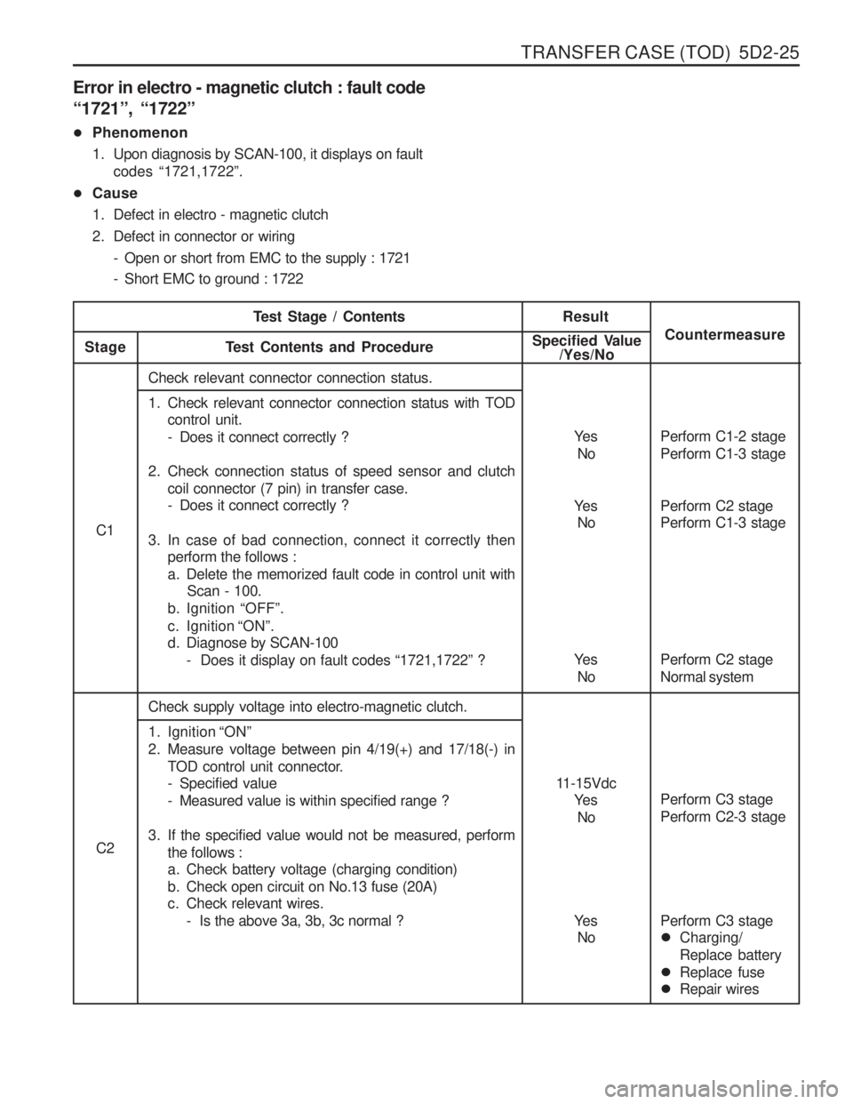
Error in electro - magnetic clutch : fault code “1721 ”, “1722 ”
� Phenomenon
1. Upon diagnosis by SCAN-100, it displays on fault
codes “1721,1722 ”.
� Cause
1. Defect in electro - magnetic clutch
2. Defect in connector or wiring
- Open or short from EMC to the supply : 1721
- Short EMC to ground : 1722
Ye sNo
C1
Ye sNo
Ye s
No
11-15Vdc Ye s
No
C2
Ye sNo
Test Stage / ContentsResult
Stage T est Contents and Procedure Specified Value
/Yes/No Countermeasure
Check relevant connector connection status.
1. Check relevant connector connection status with TOD
control unit.
- Does it connect correctly ?
2. Check connection status of speed sensor and clutch coil connector (7 pin) in transfer case.
- Does it connect correctly ?
3. In case of bad connection, connect it correctly then perform the follows :
a. Delete the memorized fault code in control unit withScan - 100.
b. Ignition “OFF ”.
c. Ignition “ON ”.
d. Diagnose by SCAN-100
- Does it display on fault codes “1721,1722 ” ?
Check supply voltage into electro-magnetic clutch.
1. Ignition “ON ”
2. Measure voltage between pin 4/19(+) and 17/18(-) in TOD control unit connector.
- Specified value
- Measured value is within specified range ?
3. If the specified value would not be measured, perform the follows :
a. Check battery voltage (charging condition)
b. Check open circuit on No.13 fuse (20A)
c. Check relevant wires.
- Is the above 3a, 3b, 3c normal ? Perform C1-2 stage Perform C1-3 stage Perform C2 stage Normal system
Perform C2 stage Perform C1-3 stage Perform C3 stage Perform C2-3 stage Perform C3 stage
�
Charging/ Replace battery
� Replace fuse
� Repair wires
Page 1175 of 1574
FATC-HAVC 7D-19
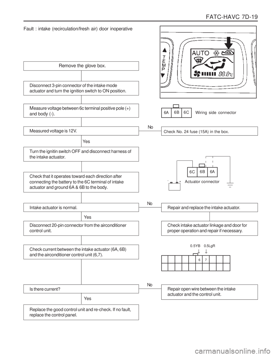
Fault : intake (recirculation/fresh air) door inoperative
Remove the glove box.
Measure voltage between 6c terminal positive pole (+)
and bo dy (-).
Measured voltage is 12V.Check No. 24 fuse (15A) in the box.
Turn the ignitin switch OFF and disconnect harness of
the intake actuator.
Ye s No
Disconnect 3-pin connector of the intake mode actuator and turn the ignition switch to ON position.
6A
6B 6C
Check that it operates toward each direction after connecting the battery to the 6C terminal of intake
actuator and ground 6A & 6B to the body.6C 6B 6A
Wiring side connector
Actuator connector
Intake actuator is normal.
Ye s
Repair and replace the intake actuator.
No
Check intake actuator linkage and door for
proper operation and repair if necessary.Disconnect 20-pin connector from the airconditioner control unit.
Check current between the intake actuator (6A, 6B) and the airconditioner control unit (6,7).
Is there current?
Ye s
Repair open wire between the intake actuator and the control unit.
No
Replace the good control unit and re-check. If no fault, replace the control panel.
67
�
0.5YB
�
0.5LgR
+
-
Page 1176 of 1574
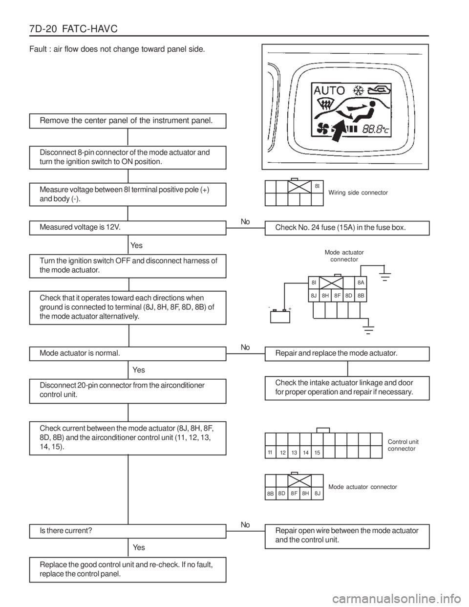
7D-20 FATC-HAVC Fault : air flow does not change toward panel side.
8H
Remove the center panel of the instrument panel.
Measure voltage between 8I terminal positive pole (+) and body (-).
Measured voltage is 12V.Check No. 24 fuse (15A) in the fuse box.
Turn the ignition switch OFF and disconnect harness of
the mode actuator.
Ye sNo
Disconnect 8-pin connector of the mode actuator and turn the ignition switch to ON position.
Check that it operates toward each directions when
ground is connected to terminal (8J, 8H, 8F, 8D, 8B) of
the mode actuator alternatively.
Mode actuator
connector
Mode actuator is normal.
Ye s
Repair and replace the mode actuator.
No
Check the intake actuator linkage and door
for proper operation and repair if necessary.Disconnect 20-pin connector from the airconditioner control unit.
Check current between the mode actuator (8J, 8H, 8F,
8D, 8B) and the airconditioner control unit (11, 12, 13,14, 15).
Is there current?
Ye s
Repair open wire between the mode actuator and the control unit.
No
Replace the good control unit and re-check. If no fault, replace the control panel.
14 15
+
-
8
IWiring side connector
8I
8J 8H 8F 8D 8B 8A
Mode actuator connector Control unit connector
12 13
11
8B 8D 8F 8J
Page 1203 of 1574
SECTION 9A
BODY WIRING SYSTEM
Schematic and Routing Diagrams . . . . . . . . 9A-2
Power Distribution . . . . . . . . . . . . . . . . . . . . . . 9A-2
Starting & Charging (Gasoline HFM) . . . . . . . 9A-3
Starting & Charging (Diesel) . . . . . . . . . . . . . . 9A-4
Fuse Box and Relay . . . . . . . . . . . . . . . . . . . 9A-5
Location of Connectors by
Wiring Harness . . . . . . . . . . . . . . . . . . . . . 9A-7
Main . . . . . . . . . . . . . . . . . . . . . . . . . . . . . . . . 9A-7
Engine Room . . . . . . . . . . . . . . . . . . . . . . . . 9A-11
Floor . . . . . . . . . . . . . . . . . . . . . . . . . . . . . . . 9A-13
Roof . . . . . . . . . . . . . . . . . . . . . . . . . . . . . . . 9A-14
Driver's Door . . . . . . . . . . . . . . . . . . . . . . . . . 9A-15
Passenger's Door . . . . . . . . . . . . . . . . . . . . . 9A-15
TABLE OF CONTENTS
Caution: Disconnect the negative battery cable before removing or installing any electrical unit or when a tool or equipment could easily come in contact with exposed electrical terminals. Disconnecting this cable will help prevent personal injury and damage to the vehicle. The ignition must also be in LOCK unless otherwisenoted.
Rear Left Door . . . . . . . . . . . . . . . . . . . . . . . 9A-16
Rear Right Door . . . . . . . . . . . . . . . . . . . . . . 9A-16
Tail Gate . . . . . . . . . . . . . . . . . . . . . . . . . . . . 9A-17
Semi Automatic Air Conditioner . . . . . . . . . . 9A-18
Full automatic Air Conditioner . . . . . . . . . . . . 9A-19
Gasoline Engine (MSE) . . . . . . . . . . . . . . . . 9A-20
Gasoline Engine (HFM) . . . . . . . . . . . . . . . . 9A-21
Diesel Engine . . . . . . . . . . . . . . . . . . . . . . . . 9A-22
Manual Transmission . . . . . . . . . . . . . . . . . . 9A-23
Automatic Transmission (BENZ) . . . . . . . . . . 9A-24
Automatic Transmission (BTRA) . . . . . . . . . . 9A-25
Driver's Seat . . . . . . . . . . . . . . . . . . . . . . . . . 9A-26