Page 942 of 1574
AUTOMATIC TRANSMISSION 5A-83
Tightening Torque 70 - 80 Nm
11. Remove the two pipes for oil cooler. Installation Notice
Tightening Torque 24.5 - 34.3 Nm
12. Remove the service hall cover on torque converter.
13. Put the alignment mark for installation, and unscrew the six mounting bolts for torque converter from drive plate through the service hole (arrow) by rotating the engine
and remove the torque converter. Installation Notice
Tightening Torque 42 Nm
7. Remove the rear propeller shaft.
Installation Notice
8. Unscrew the five bolts and remove the transfer case.
9. Disconnect the 10-Pins Plug connector from transmission.
10. Separate the locking clip on shift lever and remove the shift rod.Notice Removal and installation performed when the shift procedure should be lever is in “D” range.
Screw the six bolts mounting the torque converter through the service hole by using a mirror and rotating the engine.
Page 1003 of 1574
5B-14 MANUAL TRANSMISSION TRANSMISSION Preceding Work : Removal of the shift control cable
1 Clutch Housing
2 Oil Filler Plug............................................ 25 Nm
3 Transmission Assembly
4 Back-up Switch
5 Washer
6 Bolt ...................................................... 77-87 Nm
7 Oil Drain Plug ............................................ 25 Nm
8 Bolt ...................................................... 81-89 Nm
9 Washer
10 Front Propeller Shaft 11 Transfer Case Assembly12 Speedometer Cable
13 Rear Propeller Shaft
14 Washer
15 Bolt ...................................................... 70-80 Nm
16 Cross Member
17 Washer
18 Bolt ...................................................... 21-35 Nm
19 Washer
20 Bolt ...................................................... 62-93 Nm
21 Breather Hose
Page 1005 of 1574
5B-16 MANUAL TRANSMISSION
7. Remove the front and rear propeller shafts from thetransfercase. Installation Notice
Tightening Torque 81 - 89 Nm
70 - 90 NmFront
Rear
8. Support the transmission on an suitable jack. Unscrew the center mounting nuts and each sides
mounting bolts and remove the cross member. Installation Notice
9. Remove the transmission mounting bolts. Installation Notice
Tightening Torque (1)
Tightening Torque (2) 21 - 35 Nm62 - 93 Nm
10. Move the transmission jack backward careful and
disengage the transmission input shaft from the engine. Remove the transmission.
11. Installation should follow the removal procedure in the reverse order.
Tightening Torque 77 - 87 Nm
Page 1006 of 1574
MANUAL TRANSMISSION 5B-17
UNIT REPAIR MAJOR UNIT Preceding Work : Removal of the transmissionRemoval of the transfer case
Disassembly Procedure
1. Install the removed transmission into a fixture.
2. Remove the drain plug and drain the oil. Using a 13 mm wrench, remove the clamp bolt and position the offset lever in the 3-4 position of neutral. NoticeRemoval of the offset lever in a position other than 3-4 of neutral will be difficult.
3. Using a pin punch and a hammer, remove the roll pin to remove the shift lever from the offset lever.
4 . Using a 15 mm wrench, remove the 8 bolts from the extension housing.
5. Separate the extension housing from the case and shift cover. Separate the offset lever from the shift.NoticeDo not remove the offset lever while the extension housing is still assembled to the case.
6. Remove the offset lever from the extension housing with the detent ball and spring.
7. Remove the roll pin from either the offset lever or extension housing.
Page 1053 of 1574

Model
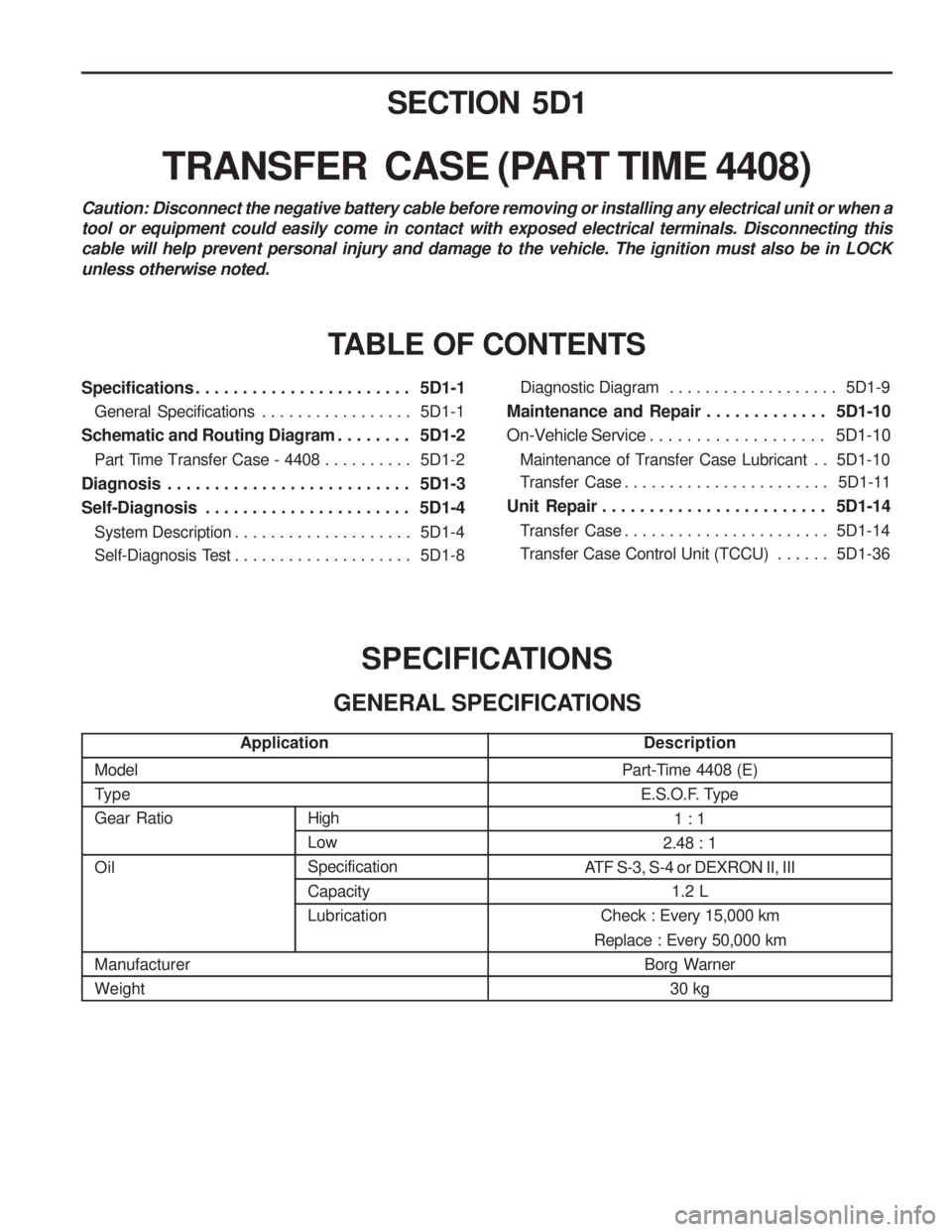
TypeGear Ratio Oil Manufacturer WeightPart-Time 4408 (E)
E.S.O.F. Type
1 : 1
2.48 : 1
ATF S-3, S-4 or DEXRON II, III
1.2 L
Check : Every 15,000 km
Replace : Every 50,000 km Borg Warner30 kg
SECTION 5D1
TRANSFER CASE (PART TIME 4408)
TABLE OF CONTENTS
SPECIFICATIONS
GENERAL SPECIFICATIONS
Caution: Disconnect the negative battery cable before removing or installing any electrical unit or when a tool or equipment could easily come in contact with exposed electrical terminals. Disconnecting thiscable will help prevent personal injury and damage to the vehicle. The ignition must also be in LOCKunless otherwise noted.
Specifications . . . . . . . . . . . . . . . . . . . . . . . 5D1-1
General Specifications . . . . . . . . . . . . . . . . . 5D1-1
Schematic and Routing Diagram . . . . . . . . 5D1-2 Part Time Transfer Case - 4408 . . . . . . . . . . 5D1-2
Diagnosis . . . . . . . . . . . . . . . . . . . . . . . . . . 5D1-3
Self-Diagnosis . . . . . . . . . . . . . . . . . . . . . . 5D1-4 System Description . . . . . . . . . . . . . . . . . . . . 5D1-4
Self-Diagnosis Test . . . . . . . . . . . . . . . . . . . . 5D1-8Diagnostic Diagram . . . . . . . . . . . . . . . . . . .
5D1-9
Maintenance and Repair . . . . . . . . . . . . . 5D1-10
On-Vehicle Service . . . . . . . . . . . . . . . . . . . 5D1-10
Maintenance of Transfer Case Lubricant . . 5D1-10
Transfer Case . . . . . . . . . . . . . . . . . . . . . . . 5D1-11
Unit Repair . . . . . . . . . . . . . . . . . . . . . . . . 5D1-14
Transfer Case . . . . . . . . . . . . . . . . . . . . . . . 5D1-14
Transfer Case Control Unit (TCCU) . . . . . . 5D1-36
High LowSpecification Capacity Lubrication
Application
Description
Page 1054 of 1574
5D1-2 TRANSFER CASE (PART TIME 4408)SCHEMATIC AND ROUTING DIAGRAM
PART TIME TRANSFER CASE - 4408
Page 1055 of 1574

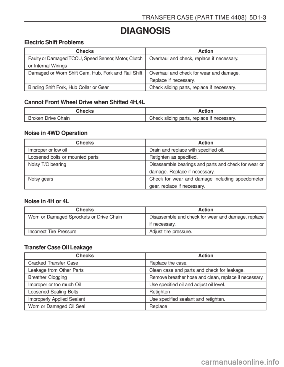
TRANSFER CASE (PART TIME 4408) 5D1-3
Cannot Front Wheel Drive when Shifted 4H,4LDIAGNOSIS
Electric Shift Problems
Action
Overhaul and check, replace if necessary. Overhaul and check for wear and damage.
Replace if necessary.
Check sliding parts, replace if necessary.
Checks
Faulty or Damaged TCCU, Speed Sensor, Motor, Clutch or Internal Wirings Damaged or Worn Shift Cam, Hub, Fork and Rail Shift Binding Shift Fork, Hub Collar or Gear
Checks
Broken Drive Chain Action
Check sliding parts, replace if necessary.
Noise in 4WD Operation
Checks
Improper or low oil Loosened bolts or mounted partsNoisy T/C bearing Noisy gears Action
Drain and replace with specified oil. Retighten as specified.Disassemble bearings and parts and check for wear or
damage. Replace if necessary. Check for wear and damage including speedometer
gear, replace if necessary.
Noise in 4H or 4L
Checks
Worn or Damaged Sprockets or Drive Chain
Incorrect Tire Pressure Action
Disassemble and check for wear and damage, replace
if necessary. Adjust tire pressure.
Transfer Case Oil Leakage
Action
Replace the case. Clean case and parts and check for leakage.
Remove breather hose and clean, replace if necessary.Use specified oil and adjust oil level.Retighten Use specified sealant and retighten. Replace
Checks
Cracked Transfer CaseLeakage from Other PartsBreather CloggingImproper or too much OilLoosened Sealing Bolts Improperly Applied Sealant Worn or Damaged Oil Seal
Page 1056 of 1574

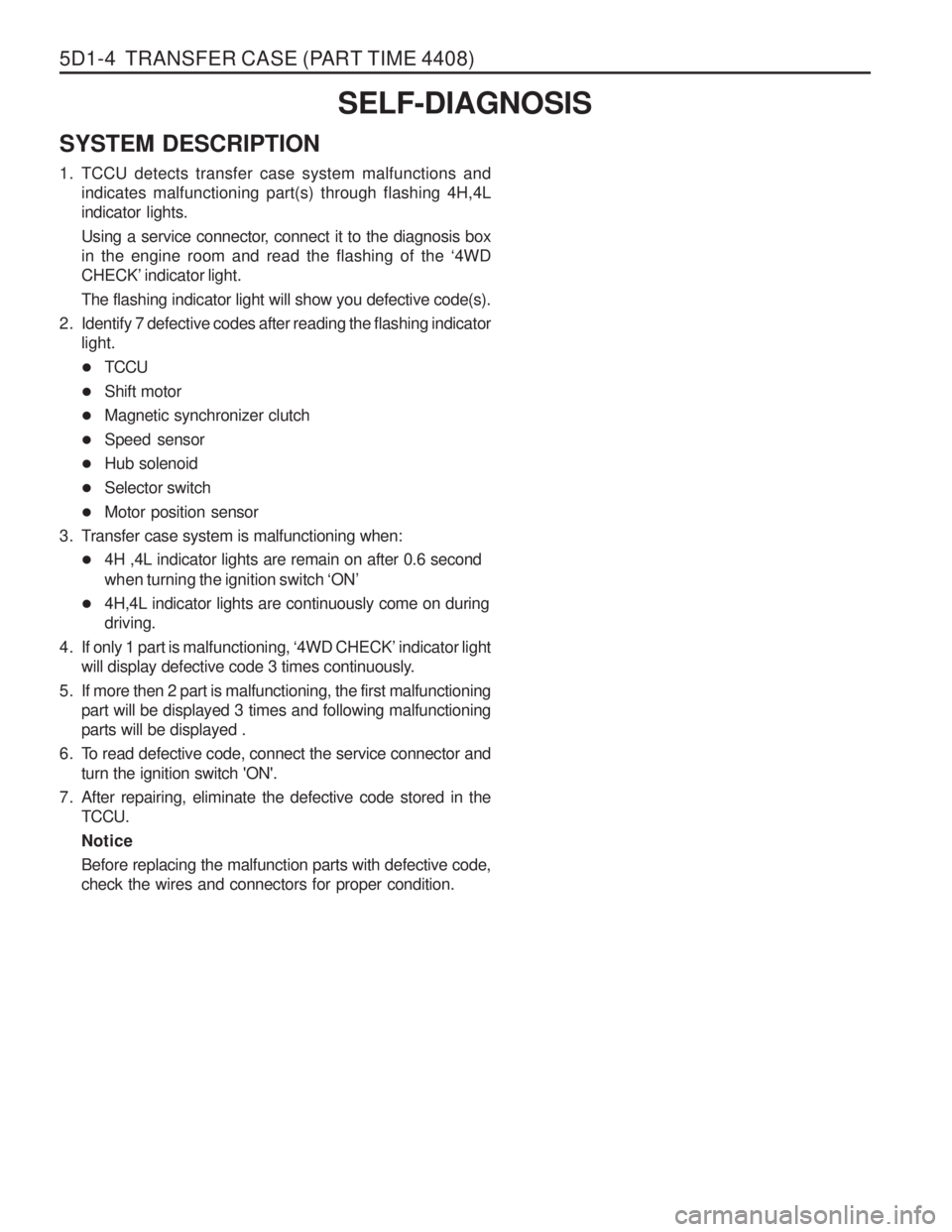
5D1-4 TRANSFER CASE (PART TIME 4408)SELF-DIAGNOSIS
SYSTEM DESCRIPTION
1. TCCU detects transfer case system malfunctions and indicates malfunctioning part(s) through flashing 4H,4L indicator lights.
Using a service connector, connect it to the diagnosis box in the engine room and read the flashing of the ‘4WD
CHECK ’ indicator light.
The flashing indicator light will show you defective code(s).
2. Identify 7 defective codes after reading the flashing indicator light.
� TCCU
� Shift motor
� Magnetic synchronizer clutch
� Speed sensor
� Hub solenoid
� Selector switch
� Motor position sensor
3. Transfer case system is malfunctioning when: � 4H ,4L indicator lights are remain on after 0.6 second when turning the ignition switch ‘ON ’
� 4H,4L indicator lights are continuously come on during driving.
4. If only 1 part is malfunctioning, ‘4WD CHECK ’ indicator light
will display defective code 3 times continuously.
5. If more then 2 part is malfunctioning, the first malfunctioning part will be displayed 3 times and following malfunctioningparts will be displayed .
6. To read defective code, connect the service connector and turn the ignition switch 'ON'.
7. After repairing, eliminate the defective code stored in the TCCU. NoticeBefore replacing the malfunction parts with defective code, check the wires and connectors for proper condition.