Page 1005 of 1574
5B-16 MANUAL TRANSMISSION
7. Remove the front and rear propeller shafts from thetransfercase. Installation Notice
Tightening Torque 81 - 89 Nm
70 - 90 NmFront
Rear
8. Support the transmission on an suitable jack. Unscrew the center mounting nuts and each sides
mounting bolts and remove the cross member. Installation Notice
9. Remove the transmission mounting bolts. Installation Notice
Tightening Torque (1)
Tightening Torque (2) 21 - 35 Nm62 - 93 Nm
10. Move the transmission jack backward careful and
disengage the transmission input shaft from the engine. Remove the transmission.
11. Installation should follow the removal procedure in the reverse order.
Tightening Torque 77 - 87 Nm
Page 1015 of 1574

5B-26 MANUAL TRANSMISSION
21. Completely compress the detent spring.
22. To install the extension housing to the case, apply sealerto the top two bolts and tighten them and tighten the 6 bolts.
23. Apply sealer to the back-up lamp switch and drain plug and tighten them.
24. Using a hammer, install the offset lever-to-shift roll pin.
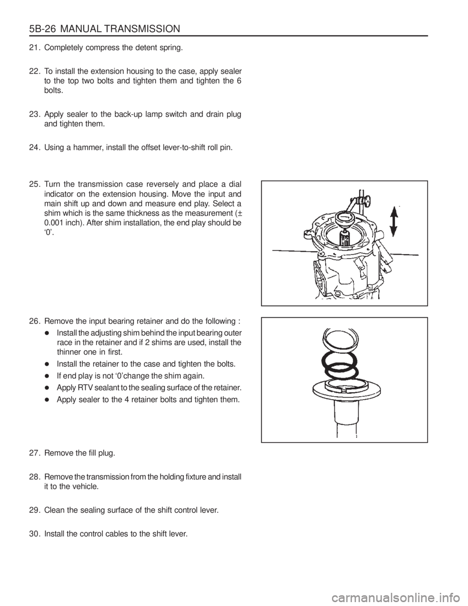
25. Turn the transmission case reversely and place a dial indicator on the extension housing. Move the input and
main shift up and down and measure end play. Select a
shim which is the same thickness as the measurement (±0.001 inch). After shim installation, the end play should be
‘0’.
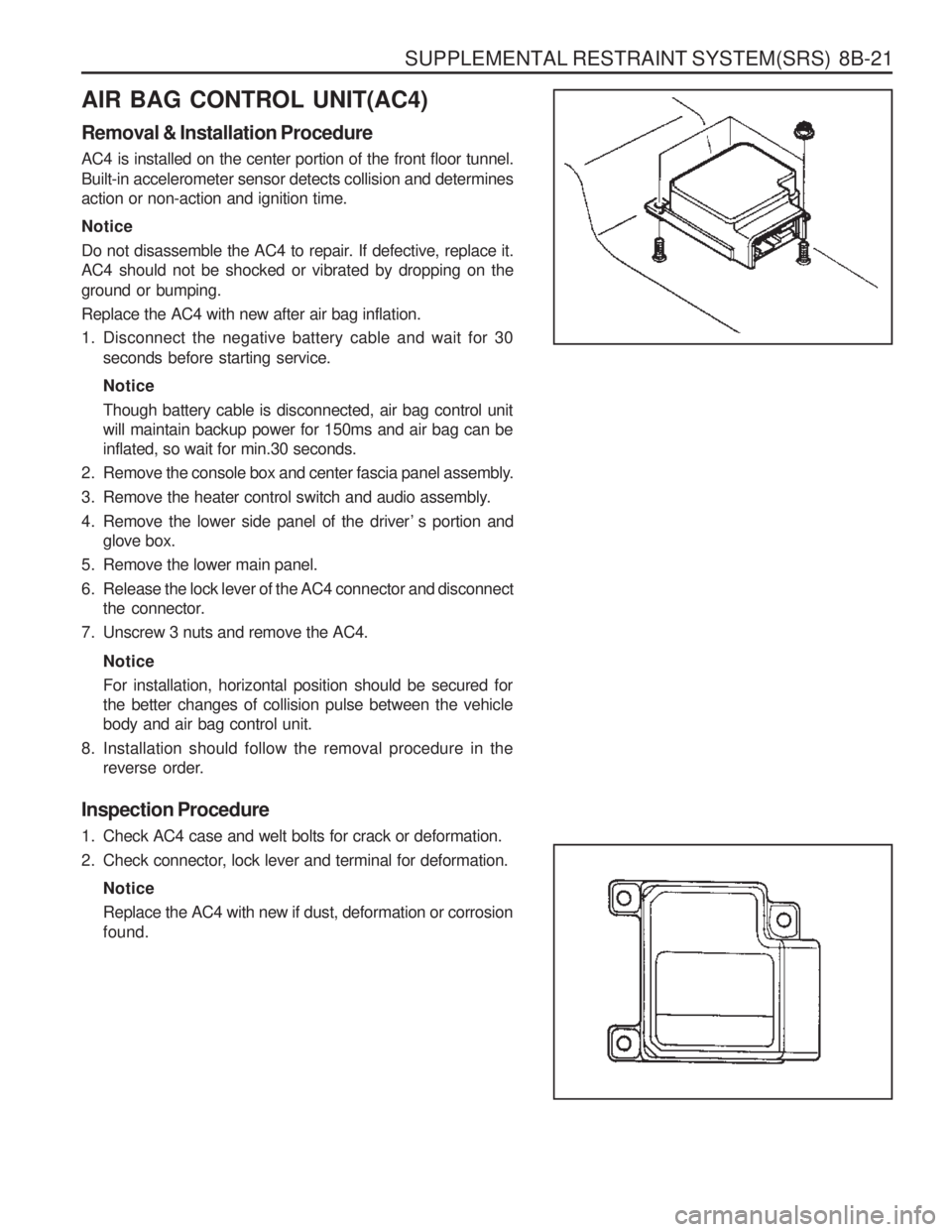
26. Remove the input bearing retainer and do the following : �Install the adjusting shim behind the input bearing outer
race in the retainer and if 2 shims are used, install thethinner one in first.
� Install the retainer to the case and tighten the bolts.
� If end play is not ‘0’change the shim again.
� Apply RTV sealant to the sealing surface of the retainer.
� Apply sealer to the 4 retainer bolts and tighten them.
27. Remove the fill plug.
28. Remove the transmission from the holding fixture and install it to the vehicle.
29. Clean the sealing surface of the shift control lever.
30. Install the control cables to the shift lever.
Page 1126 of 1574

TRANSFER CASE (TOD) 5D2-37
Replacement of Shift Motor
1. Disconnect (-) cable from battery.
2. Disconnect shift motor/clutch coil connector (black pin7)upper backside.
3. Unscrew 3 units of shift motor mounting bolts (M10).
4. Unscrew 1unit of bracket mounting bolt (M10). Installation Notice
Tightening Torque 9 - 11 Nm
Notice When disconnecting shift motor and mounting bracket, it is required to unscrew 2 units of adjusting bolts (M10) formmotor and bracket.
5. Keep shift motor even then pull rearward.
6. Clean connection surface of transfer case and shift motor.
7. If necessary, make a test by SCANNER with shift motor assembly.Notice
Do not disassemble shift motor. If necessary, replace by shift motor assembly unit.
8. Applying sealant into connecting surface for new shift motor.
9. Installation should follow the removal procedure in the reverse order. Before installation, make sure that motor position match with mode of 4H/4L switch. ReferenceWhen accord position of motor with 4H/4L switch and transfer case match position of the disconnected motor and newone.
Page 1201 of 1574

SUPPLEMENTAL RESTRAINT SYSTEM(SRS) 8B-21
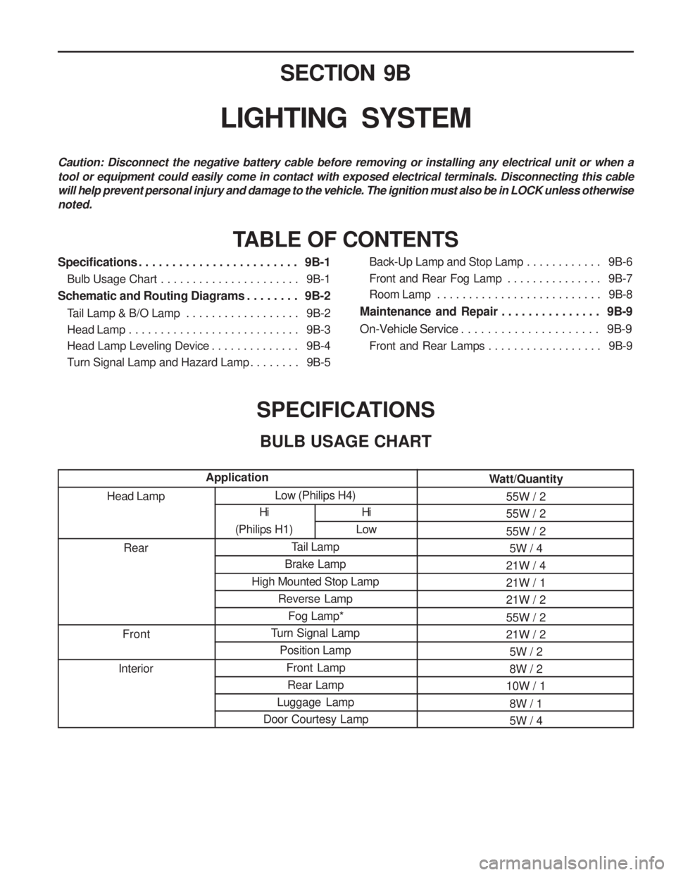
AIR BAG CONTROL UNIT(AC4) Removal & Installation Procedure AC4 is installed on the center portion of the front floor tunnel.
Built-in accelerometer sensor detects collision and determines action or non-action and ignition time. Notice
Do not disassemble the AC4 to repair. If defective, replace it. AC4 should not be shocked or vibrated by dropping on the ground or bumping. Replace the AC4 with new after air bag inflation.
1. Disconnect the negative battery cable and wait for 30seconds before starting service. Notice Though battery cable is disconnected, air bag control unit will maintain backup power for 150ms and air bag can beinflated, so wait for min.30 seconds.
2. Remove the console box and center fascia panel assembly.
3. Remove the heater control switch and audio assembly.
4. Remove the lower side panel of the driver ’ s portion and glove box.
5. Remove the lower main panel.
6. Release the lock lever of the AC4 connector and disconnect the connector.
7. Unscrew 3 nuts and remove the AC4.
NoticeFor installation, horizontal position should be secured for the better changes of collision pulse between the vehiclebody and air bag control unit.
8. Installation should follow the removal procedure in the reverse order.
Inspection Procedure
1. Check AC4 case and welt bolts for crack or deformation.
2. Check connector, lock lever and terminal for deformation. NoticeReplace the AC4 with new if dust, deformation or corrosion found.
Page 1229 of 1574

Low (Philips H4)Tail Lamp
Brake Lamp
High Mounted Stop Lamp Reverse LampFog Lamp*
Turn Signal Lamp Position Lamp
Front LampRear Lamp
Luggage Lamp
Door Courtesy Lamp SECTION 9B
LIGHTING SYSTEM
Caution: Disconnect the negative battery cable before removing or installing any electrical unit or when a tool or equipment could easily come in contact with exposed electrical terminals. Disconnecting this cable will help prevent personal injury and damage to the vehicle. The ignition must also be in LOCK unless otherwisenoted.
TABLE OF CONTENTS
SPECIFICATIONSBULB USAGE CHART
Head Lamp Rear
Front
Interior
Application
Specifications . . . . . . . . . . . . . . . . . . . . . . . . 9B-1
Bulb Usage Chart . . . . . . . . . . . . . . . . . . . . . . 9B-1
Schematic and Routing Diagrams . . . . . . . . 9B-2 Tail Lamp & B/O Lamp . . . . . . . . . . . . . . . . . . 9B-2
Head Lamp . . . . . . . . . . . . . . . . . . . . . . . . . . . 9B-3
Head Lamp Leveling Device . . . . . . . . . . . . . . 9B-4
Turn Signal Lamp and Hazard Lamp . . . . . . . . 9B-5 Back-Up Lamp and Stop Lamp . . . . . . . . . . . .
9B-6
Front and Rear Fog Lamp . . . . . . . . . . . . . . . 9B-7
Room Lamp . . . . . . . . . . . . . . . . . . . . . . . . . . 9B-8
Maintenance and Repair . . . . . . . . . . . . . . . 9B-9
On-Vehicle Service . . . . . . . . . . . . . . . . . . . . . 9B-9 Front and Rear Lamps . . . . . . . . . . . . . . . . . . 9B-9
Hi
(Philips H1)
Hi
Low Watt/Quantity
55W / 2 55W / 2 55W / 25W / 4
21W / 4 21W / 121W / 2 55W / 2 21W / 2 5W / 28W / 2
10W / 1
8W / 15W / 4