Page 808 of 1574
HYDRAULIC BRAKES 4A-11
Adjustment Procedure
1. Pedal HeightNotice If pedal height is not in specified value, loosen the stop lamp nut (B) and adjust the pedal height.
2. Pedal Stroke
Height (A) 150 mm (From the carpet)
Notice If pedal stroke is not in specified value, loosen the stop bolt and lock nut (F) and adjust the pedal stroke.
3. Free Play
Stroke (C) Mando : 138 mm
PBR : 132mm
Notice
To adjust, depress the brake pedal several times until there is no more vacuum left in the vacuum line.
To adjust, loosen the lock nut (D) of the push rod and turn the rod.
Free Play (E) 1 - 4 mm
Inspection Procedure
1. Inspect the wear of bushing.
2. Inspect the warp and bend of brake pedal.
3. Inspect the return spring of brake pedal.
4. Inspect the conductivity when connecting the tester to the stop lamp switch connector.
Page 836 of 1574

ANTILOCK BRAKE SYSTEM 4F-7
ABD SYSTEM DESCRIPTION
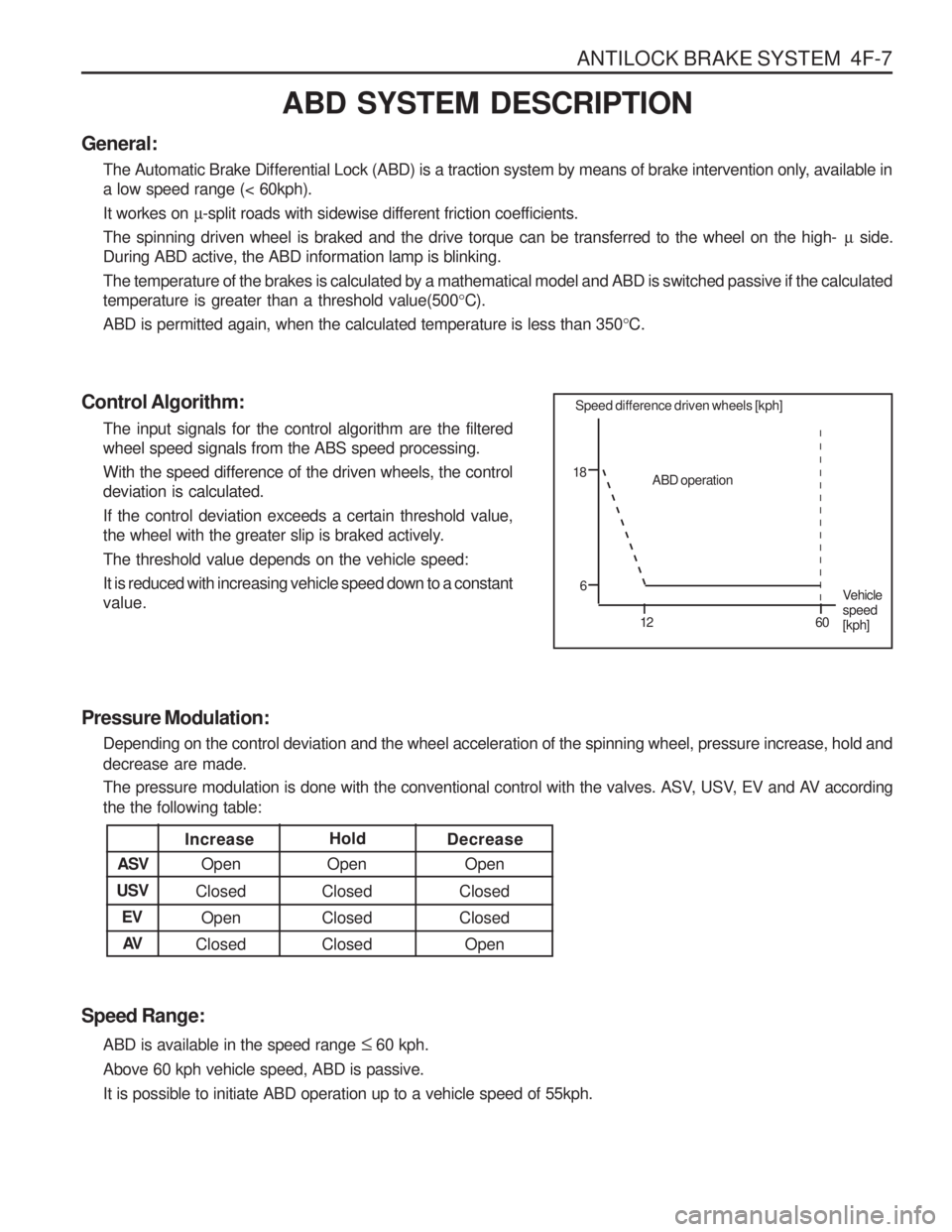
General: The Automatic Brake Differential Lock (ABD) is a traction system by means of brake intervention only, available in a low speed range (< 60kph). It workes on µ-split roads with sidewise different friction coefficients.
The spinning driven wheel is braked and the drive torque can be transferred to the wheel on the high- µ side.
During ABD active, the ABD information lamp is blinking.The temperature of the brakes is calculated by a mathematical model and ABD is switched passive if the calculated temperature is greater than a threshold value(500 °C).
ABD is permitted again, when the calculated temperature is less than 350 °C.
Control Algorithm: The input signals for the control algorithm are the filteredwheel speed signals from the ABS speed processing. With the speed difference of the driven wheels, the control deviation is calculated. If the control deviation exceeds a certain threshold value,
the wheel with the greater slip is braked actively. The threshold value depends on the vehicle speed:It is reduced with increasing vehicle speed down to a constant value.
Pressure Modulation: Depending on the control deviation and the wheel acceleration of the spinning wheel, pressure increase, hold and decrease are made.
The pressure modulation is done with the conventional control with the valves. ASV, USV, EV and AV according the the following table:
Speed Range: ABD is available in the speed range � 60 kph.
Above 60 kph vehicle speed, ABD is passive. It is possible to initiate ABD operation up to a vehicle speed of 55kph.
Increase Open
Open
Open
ASV Decrease
Hold
Closed
Closed
Closed
Closed
Closed
Open
Open
Closed
Closed
USV
EVAV
Speed difference driven wheels [kph]
18
6 12 60ABD operation
Vehicle speed[kph]
Page 838 of 1574

ANTILOCK BRAKE SYSTEM 4F-9
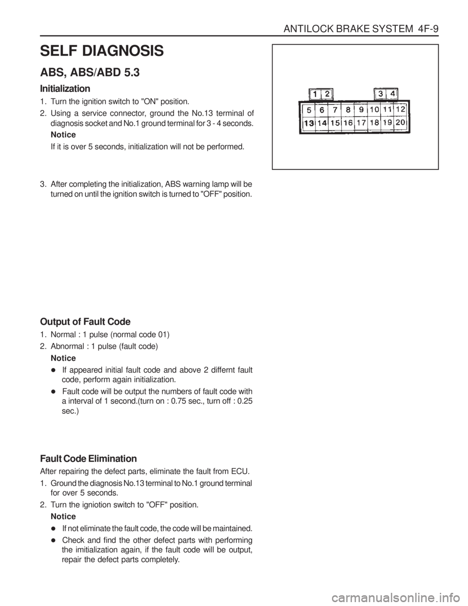
SELF DIAGNOSIS ABS, ABS/ABD 5.3 Initialization
1. Turn the ignition switch to "ON" position.
2. Using a service connector, ground the No.13 terminal ofdiagnosis socket and No.1 ground terminal for 3 - 4 seconds. Notice If it is over 5 seconds, initialization will not be performed.
3. After completing the initialization, ABS warning lamp will beturned on until the ignition switch is turned to "OFF" position.
Output of Fault Code
1. Normal : 1 pulse (normal code 01)
2. Abnormal : 1 pulse (fault code) Notice
� If appeared initial fault code and above 2 differnt fault
code, perform again initialization.
� Fault code will be output the numbers of fault code with
a interval of 1 second.(turn on : 0.75 sec., turn off : 0.25 sec.)
Fault Code Elimination After repairing the defect parts, eliminate the fault from ECU.
1. Ground the diagnosis No.13 terminal to No.1 ground terminal for over 5 seconds.
2. Turn the igniotion switch to "OFF" position. Notice
� If not eliminate the fault code, the code will be maintained.
� Check and find the other defect parts with performing
the imitialization again, if the fault code will be output,
repair the defect parts completely.
Page 840 of 1574

ANTILOCK BRAKE SYSTEM 4F-11
ABS, ABS/ABD 5.0 Initializing
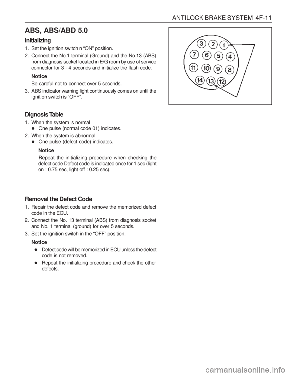
1. Set the ignition switch n “ON ” position.
2. Connect the No.1 terminal (Ground) and the No.13 (ABS) from diagnosis socket located in E/G room by use of service connector for 3 - 4 seconds and initialize the flash code. Notice Be careful not to connect over 5 seconds.
3. ABS indicator warning light continuously comes on until the ignition switch is “OFF ”.
Dignosis Table
1. When the system is normal � One pulse (normal code 01) indicates.
2. When the system is abnormal � One pulse (defect code) indicates.
Notice Repeat the initializing procedure when checking the
defect code Defect code is indicated once for 1 sec (light on : 0.75 sec, light off : 0.25 sec).
Removal the Defect Code
1. Repair the defect code and remove the memorized defect code in the ECU.
2. Connect the No. 13 terminal (ABS) from diagnosis socket and No. 1 terminal (ground) for over 5 seconds.
3. Set the ignition switch in the “OFF ” position.
Notice � Defect code will be memorized in ECU unless the defect code is not removed.
� Repeat the initializing procedure and check the otherdefects.
Page 845 of 1574

4F-16 ANTILOCK BRAKE SYSTEM
Description
� Check terminals for open or short. (When connector is removed)
� Replace the hydraulic modulator.
� Check each valve by using SCANNER's solenoid valve overriding function.
� Check connection of connector and terminals in the
ECU hydraulic modulator.
� Check terminals for open or short. (When connector is removed)
� Replace the hydraulic modulator
� Check solenoid internal resistance of the prime(ASV) valve and pilot valve(USV) : 8.04 - 9.04 �
� Check each valve by using SCANNER's solenoid valve overriding function.
� Check connection of connector and terminals in the
ECU and hydraulic modulator.
� Check terminals for open or short.(When connector is removed)
� Replace the hydraulic modulator
� Check solenoid internal resistance of the prime(ASV)valve and pilot valve(USV) : 8.04 - 9.04 �
� Check each valve by using SCANNER's solenoid valveoverriding function.
� Check connection of connector and terminals in the
ECU and hydraulic modulator.
� Check terminals for open or short.(When connector is removed)
� Replace the hydraulic modulator
� Check each valve by using SCANNER's pump motoroverriding function.
� Check resistance between pump motor ground ter-minal and battery negative terminal : total resistanceshould be less than 15 m �
� Check body ground location.
� Check relay supply voltage : IGN on : 11 - 14 V
� Relay coil internal resistance : 70 - 80 �
� Replace the hydraulic modulator
� Check by using SCANNER's stop lamp switch diag-nosing function from sensor value output function.
� Check connection of ECU connector side stop lamp switch terminal.
� Check resistance of the stop lamp, switch.
- Each end resistance value of the switch
Application
Rear / Right OUTLET Valve Function and Response of The
Valve Function and Response of The
Valve Motor Relay / Circulation Pump Stop Lamp SwitchDefect Code
20 21 2224 27
Page 846 of 1574

ANTILOCK BRAKE SYSTEM 4F-17
Application
Power Voltage
Residual Temperature Measurement (ABD only) Acceleration Sensor Signal (wire)Defect Code
28 29 42Description
when switch knob (planger) is pressed by 3mm : �
- Each ends resistance value of the switch when switch knob(plunger) is not pressed : less than 200 m �
� When brake is applied :
ECU (ABS:No.14, ABD:No.48) terminal 11 - 14 V
or VBattery.When brake is released : ECU (ABS:No.14, ABD:No.48) terminal 0 V
� Check battery voltage.
� Resistance between ECU (ABD:No.28 & 29,
ABS:No.19) pins and battery negative terminal :
less than 20 m �
� Resistance between ECU No.1 (ABS:NO.15) pin and
ignition terminal : less than 60 m �
� Check that normal voltage is applied to ECU
(ABD:No.1, ABS:No.15) pin when ignition switch is turned to "ON" or "OFF".
� Check ABS fuses of 15A and 80A.
� Replace the ECU.
� Check wire (ECU No.50) for open or loose contact.
� Check connection between connectors.
� Check relevant wires for open or short.(When connector is removed)
� Check voltage between ECU side ground (ABD:No.1,
ABS:No.15 pin) and acceleration sensor side ground(ABD:No.1, ABS:No.15 pin / ECU side ABD:No.39, ABS:No.30 pin)
(When connector is installed and power is applied)
- Voltage : less than 0.25 V
� Check voltage among related terminals.(When connector is installed and power is applied)
- Voltage between ECU (ABD:No.43, ABS:No.28 pin
and ABD:No.39, ABS:No.30 pin) : 4.75 - 5.25 V
- Signal voltage between ECU (ABD:No.51, ABS:No.10) pin and (ABD:No.39, ABS:No.30) pin : 1.95 V - 3.45 V
(Measure it by laying acceleration sensor horizon- tally and without external force)
Page 857 of 1574
4G-2 PARKING BRAKE
COMPONENT LOCATOR
PARKING BRAKE
1 Parking Brake Lever
2 Praking Brake Lamp Switch
3 Bolt
4 Bolt ........................................................ 8-18 Nm
5 Front Parking Brake Cable
6 Equalizer 7 Nut
8 Bolt
........................................................ 8-18 Nm
9 Rear Parking Brake Cable
10 Brake Drum (if Equipped with Rear Drum Brake) 11 Brake Disc (if Equipped with Rear Disc Brake)
Page 858 of 1574
PARKING BRAKE 4G-3
MAINTENANCE AND REPAIR ON-VEHICLE SERVICE PARKING BRAKE Removal & Installation Procedure
1. Disconnect the parking brake indicator switch connector.
2. Disconnect the right and left cable from equalizer whileparking brake lever is released.
3. Unscrew 8 bolts and remove the parking brake lever assembly. Installation Notice Notice
Tighten the bolts with sequence number while the lever is pulled up 4 to 6 notches.
Tightening Torque 8 - 18 Nm
4. Unscrew the frame and lower arm side cable mounting bracket bolts. Installation Notice
Tightening Torque 8 - 18 Nm